EP0219687A1 - Dispositif pour le formage par pression des têtes de bobines - Google Patents
Dispositif pour le formage par pression des têtes de bobines Download PDFInfo
- Publication number
- EP0219687A1 EP0219687A1 EP86112806A EP86112806A EP0219687A1 EP 0219687 A1 EP0219687 A1 EP 0219687A1 EP 86112806 A EP86112806 A EP 86112806A EP 86112806 A EP86112806 A EP 86112806A EP 0219687 A1 EP0219687 A1 EP 0219687A1
- Authority
- EP
- European Patent Office
- Prior art keywords
- winding head
- shell
- pressure
- winding
- guide
- Prior art date
- Legal status (The legal status is an assumption and is not a legal conclusion. Google has not performed a legal analysis and makes no representation as to the accuracy of the status listed.)
- Granted
Links
Images


Classifications
-
- H—ELECTRICITY
- H02—GENERATION; CONVERSION OR DISTRIBUTION OF ELECTRIC POWER
- H02K—DYNAMO-ELECTRIC MACHINES
- H02K15/00—Processes or apparatus specially adapted for manufacturing, assembling, maintaining or repairing of dynamo-electric machines
- H02K15/20—Shaping or compacting conductors or winding heads after the installation of the winding in the cores or machines; Applying fastening means on winding heads
- H02K15/24—Shaping or compacting winding heads
- H02K15/26—Applying fastening means on winding heads
-
- H—ELECTRICITY
- H02—GENERATION; CONVERSION OR DISTRIBUTION OF ELECTRIC POWER
- H02K—DYNAMO-ELECTRIC MACHINES
- H02K15/00—Processes or apparatus specially adapted for manufacturing, assembling, maintaining or repairing of dynamo-electric machines
- H02K15/12—Impregnating, moulding insulation, heating or drying of windings, stators, rotors or machines
-
- Y—GENERAL TAGGING OF NEW TECHNOLOGICAL DEVELOPMENTS; GENERAL TAGGING OF CROSS-SECTIONAL TECHNOLOGIES SPANNING OVER SEVERAL SECTIONS OF THE IPC; TECHNICAL SUBJECTS COVERED BY FORMER USPC CROSS-REFERENCE ART COLLECTIONS [XRACs] AND DIGESTS
- Y10—TECHNICAL SUBJECTS COVERED BY FORMER USPC
- Y10T—TECHNICAL SUBJECTS COVERED BY FORMER US CLASSIFICATION
- Y10T29/00—Metal working
- Y10T29/49—Method of mechanical manufacture
- Y10T29/49002—Electrical device making
- Y10T29/49009—Dynamoelectric machine
-
- Y—GENERAL TAGGING OF NEW TECHNOLOGICAL DEVELOPMENTS; GENERAL TAGGING OF CROSS-SECTIONAL TECHNOLOGIES SPANNING OVER SEVERAL SECTIONS OF THE IPC; TECHNICAL SUBJECTS COVERED BY FORMER USPC CROSS-REFERENCE ART COLLECTIONS [XRACs] AND DIGESTS
- Y10—TECHNICAL SUBJECTS COVERED BY FORMER USPC
- Y10T—TECHNICAL SUBJECTS COVERED BY FORMER US CLASSIFICATION
- Y10T29/00—Metal working
- Y10T29/51—Plural diverse manufacturing apparatus including means for metal shaping or assembling
-
- Y—GENERAL TAGGING OF NEW TECHNOLOGICAL DEVELOPMENTS; GENERAL TAGGING OF CROSS-SECTIONAL TECHNOLOGIES SPANNING OVER SEVERAL SECTIONS OF THE IPC; TECHNICAL SUBJECTS COVERED BY FORMER USPC CROSS-REFERENCE ART COLLECTIONS [XRACs] AND DIGESTS
- Y10—TECHNICAL SUBJECTS COVERED BY FORMER USPC
- Y10T—TECHNICAL SUBJECTS COVERED BY FORMER US CLASSIFICATION
- Y10T29/00—Metal working
- Y10T29/51—Plural diverse manufacturing apparatus including means for metal shaping or assembling
- Y10T29/5147—Plural diverse manufacturing apparatus including means for metal shaping or assembling including composite tool
Definitions
- the invention relates to a device for compression molding a winding head according to the preamble of claim 1; such a device is known from DE-GM 76 40 891.
- a one-piece molded shell corresponding to the entire intended winding head contour is pressed axially onto a winding head above the end face of a stator core up to the front edge of the shaped shell against the end face of the stator core;
- Such a winding head must already be bandaged, since otherwise not all the winding wires can be gripped without damage and pressed together with sufficient all-round pressure to form the desired winding head contour with rounded end edges.
- a device is to be created with which, in particular, the shaping of a winding head, which ensures full later operational reliability of the electric motor, is also possible if its coils only protrude from the end groove ends of the stator core as they previously, for example, mechanically are wrapped in the grooves or inserted as loosely pre-wound coils and are therefore preformed or pre-consolidated by no further finishing, in particular no additional bandaging.
- the device according to the invention it is possible first to fix the winding shape up to the axial opening towards the pressure molding shell by the axial insertion of the mold core and the radial feeding of the outer limiting molding shell;
- the axial pressure-molded shell can then be pushed axially against the winding head largely independently of the fill factor of the molded-shell device formed in this way from the molded core, limiting molded shells and pressure-molded shells until the winding wires thereof, preferably with plastic deformation, under sufficient pressure on all sides stand, all of the winding wires being able to be grasped without the risk of kinking during the feeding of the pressure molding shell by the guide fingers which do not take up any useful winding space and can nevertheless be formed in the sense of sufficient strength.
- the design of the Invention provided to additionally form axial, on the pressure-mold shell, immersing in spaces between the winding head and its winding in the radial or tangential direction when the pressure-molding shell is axially advanced, inner or outer pressure fingers. Furthermore, to ensure a sufficient Ab Standes between the winding head end face of the stator core and the windings of the winding head expediently attached to the limiting molded shell in the space between the winding head and the end face of the stator core radially immersed distance projections.
- the guide projections as guide fingers and the guide recesses as grooves, as well as the pressure fingers and distance projections, are each integrally molded or molded onto the pressure mold shell or fastening mold shell or the inner mold core are.
- the mold shell device according to the invention can be used both for permanent molding of a prefixed, e.g. use bandaged winding head as well as a loosely wound winding head that will later be solidified using the baking varnish method;
- the guide fingers or pressure fingers are provided according to a further embodiment of the invention or chamfer distance projections at their free ends on the flanks which grip the winding of the winding head in the sense of a funnel-shaped winding detection.
- FIGS. 2 to 6 show the molded-shell device placed on a holding device 8 with inserted stator core 1 and its compression-molded winding heads 11, 12. The essential components of the molded-shell device are first described using the perspective exploded view according to FIGS. 2 to 6.
- the molding shell device contains a lower molding shell 7 forming the lower winding head 12 and an upper pressure molding shell 2 forming the upper winding head 11.
- the pressure molding shell 2 essentially consists of a pressure part having a curved winding head end contour 25 and on its inner and outer peripheral surface Outer guide fingers 21 and inner guide fingers 22, as well as outer pressure fingers 23 and inner pressure fingers 24, which are integrally formed and protrude axially beyond the end face contour 25.
- An inner mold core 3 points at its upper end to the inner guide fingers 22 and the inner pressure fingers 24 of the pressure molding shell 2 corresponding guide grooves 31 and its lower end to inner guide fingers 71 of the lower shell 7 corresponding guide grooves.
- a limiting molded shell 4, 5 is divided into at least two parts 4 or 5, which can be fed radially and brought together.
- the limiting molded shell 4, 5 has on its inner circumferential surfaces corresponding to the outer guide fingers 21 and pressure fingers 23 of the pressure molded shell 2 guide grooves 41 and 51 respectively.
- Spacer projections 42, 52 are integrally formed radially in one piece on the lower edge of the limiting molded shell 4, 5, which, when the two parts of the limiting molded shell 4, 5 lie against the winding head 11 to be molded, a sufficient distance between the end face of the stator core 1 and the overlying winding wires of the winding head 11 to be formed.
- a universal terminal to be held on the stator core, by means of which the coil winding ends can be pre-fixed or contacted in an advantageous manner, for example with a thermal monitor pre-assembled at the universal terminal and with terminals for external feed lines .
- FIG. 5 shows an outer slip ring 6, which is provided in the present exemplary embodiment for holding the two-part limiting molded shell 4.5 together, and which likewise has an opening 61 corresponding to the opening 43 of the limiting molded shell 4.5 for the universal terminal to be held on the stator core 1.
- the axially slidable pressure rings for example radially feedable pressure jaws can also be provided.
- the wound stator core 1 with the preformed or only loosely wound winding heads 11, 12 according to FIG. 1 with inserted mold core 3 is inserted into the lower mold shell 7.
- the wires of the lower end winding 12 are fed through the guide fingers 71 without risk of damage or kinking in their entirety to the end form 7 incorporated into the lower shell 7 as a closed contour.
- the two parts of the outer limiting molded shell 4, 5 are fed radially.
- the radial spacing projections 42, 52 reach under the lower side of the winding head 11 and ensure a sufficient distance between the end face of the stator core 1 and the opposite parts of the winding head 11.
- the outer contour of the winding head 11 to be aimed for is now defined except for the upper axial opening, into which the pressure-forming shell 2 is subsequently inserted.
- the guide fingers 21, 22 slide in the corresponding guide grooves 31 of the inner mold core 3. Because the guide fingers 21, 22 advantageously lie outside on the one hand the winding head end contour 25 of the pressure-molding shell 2 are arranged and, on the other hand, plunge radially into the corresponding guide grooves 31 of the mold core 3, on the one hand no usable winding space is lost and on the other hand the guide fingers 21, 22 can be designed to be sufficiently reliable and at their free ends in the sense of a funnel-shaped detection of the winding head parts coming to the opposite side are provided with beveled flanks.
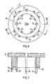
- inner or outer pressure fingers 23 or 24 are additionally molded onto the pressure molding shell 2, which - As can be seen in particular from FIGS. 7, 8 — in contrast to the guide fingers 21, 22, they also partially extend into the area of the end face contour 25 of the pressure-forming shell 2.
- the pressure fingers 23, 24 are also advantageously provided at their free ends with flanks which are chamfered in the sense of a funnel-shaped gradual detection of the opposite winding wires.
- the guide fingers that appear only in the distorted view in the section line VII-VII according to FIG. 8 are not shown.
- the distribution of the outer pressure fingers 23 and the inner pressure finger 24 in FIG. 8 corresponds to the formation of a two-pole single-phase winding arranged in two winding layers, each with a main and auxiliary phase and thus a total of four coil groups, the spaces between two adjacent coil groups alternating from the upper to the lower winding layer, each by 90 ° offset around the circumference.
- the particularly easy-to-manufacture and easy-to-use device according to the invention for compression molding an already pre-fixed or only loosely wound winding head ensures damage-free detection of all winding wires and such a deformation pressure that all winding wires after the compression molding and the subsequent optionally provided baking varnish solidify the desired winding head end contour without the risk of springback or Are released from their bandage.
Landscapes
- Engineering & Computer Science (AREA)
- Manufacturing & Machinery (AREA)
- Power Engineering (AREA)
- Manufacture Of Motors, Generators (AREA)
- Eye Examination Apparatus (AREA)
- Magnetic Resonance Imaging Apparatus (AREA)
Applications Claiming Priority (2)
| Application Number | Priority Date | Filing Date | Title |
|---|---|---|---|
| DE3534923 | 1985-09-30 | ||
| DE3534923 | 1985-09-30 |
Publications (2)
| Publication Number | Publication Date |
|---|---|
| EP0219687A1 true EP0219687A1 (fr) | 1987-04-29 |
| EP0219687B1 EP0219687B1 (fr) | 1989-08-30 |
Family
ID=6282420
Family Applications (1)
| Application Number | Title | Priority Date | Filing Date |
|---|---|---|---|
| EP86112806A Expired EP0219687B1 (fr) | 1985-09-30 | 1986-09-16 | Dispositif pour le formage par pression des têtes de bobines |
Country Status (6)
| Country | Link |
|---|---|
| US (1) | US4696631A (fr) |
| EP (1) | EP0219687B1 (fr) |
| DE (1) | DE3665383D1 (fr) |
| DK (1) | DK462086A (fr) |
| IE (1) | IE57481B1 (fr) |
| NO (1) | NO168400C (fr) |
Families Citing this family (11)
| Publication number | Priority date | Publication date | Assignee | Title |
|---|---|---|---|---|
| JPH01186143A (ja) * | 1988-01-19 | 1989-07-25 | Olympus Optical Co Ltd | 無鉄心電機子とその製造方法及び無鉄心電機子成形用金型 |
| US5806169A (en) * | 1995-04-03 | 1998-09-15 | Trago; Bradley A. | Method of fabricating an injected molded motor assembly |
| DE10045215A1 (de) * | 2000-09-13 | 2002-03-28 | Bosch Gmbh Robert | Verfahren zur Herstellung eines Bauteils einer elektrischen Maschine bzw. Vorrichtung zum Durchführen des Verfahrens |
| CZ20031901A3 (cs) | 2001-01-09 | 2003-11-12 | Black & Decker Inc. | Elektrický motor s kotvou potaženou tepelně vodivým plastem |
| US7096566B2 (en) * | 2001-01-09 | 2006-08-29 | Black & Decker Inc. | Method for making an encapsulated coil structure |
| US6946758B2 (en) | 2001-01-09 | 2005-09-20 | Black & Decker Inc. | Dynamoelectric machine having encapsulated coil structure with one or more of phase change additives, insert molded features and insulated pinion |
| US7814641B2 (en) | 2001-01-09 | 2010-10-19 | Black & Decker Inc. | Method of forming a power tool |
| WO2008032194A2 (fr) * | 2006-09-15 | 2008-03-20 | Schlumberger Technology B.V. | Procédés et systèmes pour la diagraphie d'ouverture à l'aide de communication radiofréquence |
| CN112713733B (zh) * | 2020-12-24 | 2022-07-26 | 青岛成信马达有限公司 | 一种电机定子线圈的卧式整形机 |
| CN114614642B (zh) * | 2022-05-10 | 2022-07-19 | 常州市南方电机有限公司 | 一种电磁制动三相异步电机 |
| US12078057B1 (en) * | 2023-04-18 | 2024-09-03 | Well Resolutions Technology | Systems and apparatus for downhole communication |
Citations (3)
| Publication number | Priority date | Publication date | Assignee | Title |
|---|---|---|---|---|
| US1982279A (en) * | 1928-04-05 | 1934-11-27 | Herbert F Apple | Apparatus for molding plastic material |
| US2019064A (en) * | 1933-12-02 | 1935-10-29 | Herbert F Apple | Armature mold |
| DE2327150A1 (de) * | 1972-06-14 | 1973-12-13 | Elektrotehnitschki Inst Poduze | Verfahren und zweiteilige muschelartige vorrichtung fuer die verwendung thermoplastischer lackdraehte in der herstellung von wicklungen umlaufender elektrischer maschinen |
Family Cites Families (1)
| Publication number | Priority date | Publication date | Assignee | Title |
|---|---|---|---|---|
| US3058156A (en) * | 1960-03-11 | 1962-10-16 | Us Electrical Motors Inc | Mold structure for encapsulating dynamoelectric machinery |
-
1986
- 1986-08-13 NO NO863265A patent/NO168400C/no unknown
- 1986-09-16 DE DE8686112806T patent/DE3665383D1/de not_active Expired
- 1986-09-16 EP EP86112806A patent/EP0219687B1/fr not_active Expired
- 1986-09-29 IE IE2573/86A patent/IE57481B1/en not_active IP Right Cessation
- 1986-09-29 DK DK462086A patent/DK462086A/da not_active Application Discontinuation
- 1986-09-30 US US06/913,813 patent/US4696631A/en not_active Expired - Lifetime
Patent Citations (3)
| Publication number | Priority date | Publication date | Assignee | Title |
|---|---|---|---|---|
| US1982279A (en) * | 1928-04-05 | 1934-11-27 | Herbert F Apple | Apparatus for molding plastic material |
| US2019064A (en) * | 1933-12-02 | 1935-10-29 | Herbert F Apple | Armature mold |
| DE2327150A1 (de) * | 1972-06-14 | 1973-12-13 | Elektrotehnitschki Inst Poduze | Verfahren und zweiteilige muschelartige vorrichtung fuer die verwendung thermoplastischer lackdraehte in der herstellung von wicklungen umlaufender elektrischer maschinen |
Also Published As
| Publication number | Publication date |
|---|---|
| NO168400C (no) | 1992-02-12 |
| DE3665383D1 (en) | 1989-10-05 |
| NO863265L (no) | 1987-03-31 |
| EP0219687B1 (fr) | 1989-08-30 |
| IE57481B1 (en) | 1993-02-10 |
| NO168400B (no) | 1991-11-04 |
| DK462086A (da) | 1987-03-31 |
| US4696631A (en) | 1987-09-29 |
| DK462086D0 (da) | 1986-09-29 |
| IE862573L (en) | 1987-03-30 |
| NO863265D0 (no) | 1986-08-13 |
Similar Documents
| Publication | Publication Date | Title |
|---|---|---|
| DE4301234B4 (de) | Verfahren und Einrichtung zum Herstellen von Ankern für elektrodynamische Maschinen | |
| DE69120597T2 (de) | Verfahren zur Herstellung eines Stators | |
| EP0121173B1 (fr) | Méthode de fabrication d'un paquet de tôles feuilletées pour machines et appareils électriques | |
| EP0219687B1 (fr) | Dispositif pour le formage par pression des têtes de bobines | |
| DE102018202945A1 (de) | Elektrische Maschine und Fahrzeug mit einer solchen | |
| DE3929331C1 (de) | Verfahren zur Herstellung und zum Bewickeln von für Elektro-Motore mit Innenläufer bestimmten Statorblechpaketen | |
| DE202008017892U1 (de) | Statorsegment und Stator | |
| DE1962932B2 (de) | Anordnung zur Halterung der Feldwicklung auf einem ausgeprägten Standerpol einer dynamoelektrischen Maschine | |
| DE3855563T2 (de) | Ständerendglied | |
| WO2018041836A1 (fr) | Procédé pour réaliser et introduire une enroulement de fil | |
| DE2630183B2 (de) | Verfahren und Vorrichtung zum Einziehen von Wicklungen in Nuten von Ankern und Statoren von Elektromotoren | |
| DE3631943C2 (fr) | ||
| DE2736932C3 (de) | Halterung für Stator-Wickelköpfe elektrischer Maschinen | |
| WO2014075877A2 (fr) | Stator pour un moteur électrique et procédé de production du stator | |
| DE2415839C2 (de) | Anordnung zur räumlichen Fixierung und Isolierung der Wickelköpfe von Statorspulen bei Außenläufermotoren | |
| EP1073180B1 (fr) | Isolation entre un paquet de tôles avec encoches et un enroulement avec têtes d'enroulement formé dans ces encoches | |
| DE202006007619U1 (de) | Glockenankerspule | |
| DE19633155A1 (de) | Einrichtungen und Verfahren zum Einziehen von Statorwicklungs-Spulengruppen in einen Statorkern | |
| DE2827139C2 (fr) | ||
| DE8527889U1 (de) | Vorrichtung zur Formpressung eines Wickelkopfes | |
| DE3012496C2 (de) | Durch Verbacken des gewickelten Wikklungsdrahtes mit einem backfähigem Depotmaterial verfestigte Spulenwicklung | |
| EP0018596B1 (fr) | Corps de bobine pour enroulements de fil électrique | |
| EP2479869B1 (fr) | Fabrication d'un stator de moteur électrique | |
| DE475223C (de) | Selbsttragende Ringspule | |
| DE8903959U1 (de) | Elektrische Maschine mit einem Ständerblechpaket |
Legal Events
| Date | Code | Title | Description |
|---|---|---|---|
| PUAI | Public reference made under article 153(3) epc to a published international application that has entered the european phase |
Free format text: ORIGINAL CODE: 0009012 |
|
| AK | Designated contracting states |
Kind code of ref document: A1 Designated state(s): DE GB SE |
|
| 17P | Request for examination filed |
Effective date: 19870326 |
|
| 17Q | First examination report despatched |
Effective date: 19881202 |
|
| GRAA | (expected) grant |
Free format text: ORIGINAL CODE: 0009210 |
|
| AK | Designated contracting states |
Kind code of ref document: B1 Designated state(s): DE GB SE |
|
| REF | Corresponds to: |
Ref document number: 3665383 Country of ref document: DE Date of ref document: 19891005 |
|
| GBT | Gb: translation of ep patent filed (gb section 77(6)(a)/1977) | ||
| PLBE | No opposition filed within time limit |
Free format text: ORIGINAL CODE: 0009261 |
|
| STAA | Information on the status of an ep patent application or granted ep patent |
Free format text: STATUS: NO OPPOSITION FILED WITHIN TIME LIMIT |
|
| 26N | No opposition filed | ||
| PGFP | Annual fee paid to national office [announced via postgrant information from national office to epo] |
Ref country code: SE Payment date: 19900913 Year of fee payment: 5 |
|
| PG25 | Lapsed in a contracting state [announced via postgrant information from national office to epo] |
Ref country code: SE Effective date: 19910917 |
|
| EUG | Se: european patent has lapsed |
Ref document number: 86112806.4 Effective date: 19920408 |
|
| REG | Reference to a national code |
Ref country code: GB Ref legal event code: 732E |
|
| REG | Reference to a national code |
Ref country code: GB Ref legal event code: IF02 |
|
| PGFP | Annual fee paid to national office [announced via postgrant information from national office to epo] |
Ref country code: DE Payment date: 20031002 Year of fee payment: 18 |
|
| PGFP | Annual fee paid to national office [announced via postgrant information from national office to epo] |
Ref country code: GB Payment date: 20040902 Year of fee payment: 19 |
|
| PG25 | Lapsed in a contracting state [announced via postgrant information from national office to epo] |
Ref country code: DE Free format text: LAPSE BECAUSE OF NON-PAYMENT OF DUE FEES Effective date: 20050401 |
|
| PG25 | Lapsed in a contracting state [announced via postgrant information from national office to epo] |
Ref country code: GB Free format text: LAPSE BECAUSE OF NON-PAYMENT OF DUE FEES Effective date: 20050916 |
|
| GBPC | Gb: european patent ceased through non-payment of renewal fee |
Effective date: 20050916 |