EP0219692B1 - Procédé pour la fabrication d'un refroidisseur et refroidisseur ainsi fabriqué - Google Patents
Procédé pour la fabrication d'un refroidisseur et refroidisseur ainsi fabriqué Download PDFInfo
- Publication number
- EP0219692B1 EP0219692B1 EP86112859A EP86112859A EP0219692B1 EP 0219692 B1 EP0219692 B1 EP 0219692B1 EP 86112859 A EP86112859 A EP 86112859A EP 86112859 A EP86112859 A EP 86112859A EP 0219692 B1 EP0219692 B1 EP 0219692B1
- Authority
- EP
- European Patent Office
- Prior art keywords
- heat sink
- pipe
- middle portion
- flow passage
- heat
- Prior art date
- Legal status (The legal status is an assumption and is not a legal conclusion. Google has not performed a legal analysis and makes no representation as to the accuracy of the status listed.)
- Expired
Links
Images

Classifications
-
- H—ELECTRICITY
- H10—SEMICONDUCTOR DEVICES; ELECTRIC SOLID-STATE DEVICES NOT OTHERWISE PROVIDED FOR
- H10W—GENERIC PACKAGES, INTERCONNECTIONS, CONNECTORS OR OTHER CONSTRUCTIONAL DETAILS OF DEVICES COVERED BY CLASS H10
- H10W40/00—Arrangements for thermal protection or thermal control
- H10W40/40—Arrangements for thermal protection or thermal control involving heat exchange by flowing fluids
- H10W40/47—Arrangements for thermal protection or thermal control involving heat exchange by flowing fluids by flowing liquids, e.g. forced water cooling
-
- F—MECHANICAL ENGINEERING; LIGHTING; HEATING; WEAPONS; BLASTING
- F28—HEAT EXCHANGE IN GENERAL
- F28D—HEAT-EXCHANGE APPARATUS, NOT PROVIDED FOR IN ANOTHER SUBCLASS, IN WHICH THE HEAT-EXCHANGE MEDIA DO NOT COME INTO DIRECT CONTACT
- F28D7/00—Heat-exchange apparatus having stationary tubular conduit assemblies for both heat-exchange media, the media being in contact with different sides of a conduit wall
- F28D7/04—Heat-exchange apparatus having stationary tubular conduit assemblies for both heat-exchange media, the media being in contact with different sides of a conduit wall the conduits being spirally coiled
Definitions
- This invention relates to a method for producing a cooling member and a cooling member produced by the method.
- a heat sink made of a highly heat-conductive metal such as copper or aluminum, through which a circulation passage of a liquid coolant is provided in a zigzag form.
- a required number of the heat sinks are placed between semiconductor elements such as diodes, thyristors, gate turn off (GTO) thyristors and the like, respectively, and the coolant passages formed in the heat sinks are connected together through a number of coolant supplying pipes made of an electrically insulating material so as to provide a coolant circulating path.
- the thickness of the heat sink becomes comparatively thick not only because of the heat-conductive metal member through which the zigzag formed circulation passage is provided, but also because of the zigzag-formed configuration, the head loss caused when the liquid coolant flows through the circulation passage in each heat sink becomes high, thus requiring a large capacity of the pump for circulating the liquid coolant therethrough.
- the temperature of the liquid coolant becomes much different between the inlet portion and outlet portion of the coolant passage in each heat sink, which entails a difficulty of increasing the thermal stress in the semiconductor element and requiring a heat exchange of a large capacity in the coolant circulating path.
- a heat sink for cooling power semiconductor elements consisting of a chamber which is traversed form the inlet port to the outlet port with a cooling medium, wherein the chamber consists of at least two caps and at least a spiral dividing wall which together with the caps forms a channel for the cooling medium.
- An object of this invention is to provide a heat sink for cooling stacked means such as semiconductor elements, and a method for producing the heat sink wherein the disadvantages of the conventional technique can be substantially eliminated.
- Another object of the invention is to provide a heat sink and a method for producing the same, which are simple and economical, and capable of eliminating the possibility of leakage.
- Still another object of the invention is to provide a heat sink, the thickness of which is substantially reduced while the operational characteristics thereof are improved remarkably.
- a method for producing a heat sink comprising the steps of preparing a pipe made of a heat conductive material, bending the pipe at a middle portion thereof into a loop form such that two portions of the pipe provided on both sides of the middle portion extend side by side in one direction from the bend middle portion, and winding the thus bent pipe into a spiral shape with the bent middle portion held at the center, and both the side portions of the pipe formed into a forward flow passage and a return flow passage for a liquid coolant circulating through the heat sink thus produced.
- a heat sink for cooling stacked means consisting of a pipe made of a heat conductive material, comprising a forward flow passage for a liquid coolant, a return flow passage for the liquid coolant, and a middle portion provided between the forward flow passage and the return flow passage, the middle portion being bent and wound so that the forward and return flow passages are formed into spirals starting from the middle portion.
- the pipe is constructed to provide a rectangular cross-section, and the forward flow passage and return flow passage are formed by two side portions of the pipe which are wound side by side into the spiral shape.
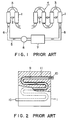
- a number of heat sinks 1 of a liquid cooled type are ordinarily piled up in the form of a stack 4, each pad being interposed between two adjacent semiconductor elements 2 of a flat shape, such as diodes, thyristors, GTOs and the like as shown in FIG. 1, and compressed together under application of a pressure of several tons.
- the heat sinks 1 are interconnected by a number of pipes 3 made of an insulating material.
- a liquid coolant 5 such as water is supplied through main pipes 6 also made of an insulating material under the action of a pump 8, and the heat in the circulated coolant is exchanged by a heat exchanger 7 provided in the circulation passage of the liquid coolant.
- Each of the heat sinks 1 in the above described arrangement comprises a block of a heat-conductive material such as copper or aluminium, with a coolant passage 9 of an undulated configuration form through the block.
- the liquid coolant 5 flows in and out of the coolant passage 9 of each heat sink 1 through inlet and outlet ports 10 provided at the ends of the passage 9.
- the aforementioned passage 9 may otherwise be formed by use of a tube II made of copper or aluminum, which is undulated and casted in the block as shown in FIG. 2.
- the undulated passage 9 provides a long length and increases the heat-exchanging surface area of the heat sink I.
- an increase in the number of bending portions and steepening of the curvature increases the head loss of liquid coolant 5, and increases the required capacity of the circulation pump 8.
- the passage 9 is simply undulated without duplication or else, the temperature of the coolant passing through the passage 9 is low at the inlet portion and high at the outlet portion of the passage 9.
- Such a temperature difference in a single pad creates a thermal stress in the semiconductor element 2 contacting the heat sink I.
- the capacity of the heat exchanger 7 must be increased, which in turn increases the size of semiconductor apparatus cooled by the heat sinks.
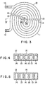
- a heat sink I comprises solely a cooling pipe 12 made of a heat conductive material such as copper or aluminum without using the block of the conventional construction.
- the cooling pipe 12 is bent in a middle part thereof into a loop form so that both the side portions of the pipe 12 excepting the middle part are brought together to be extended side by side in one direction from the bent middle part of the pipe 12.
- the pipe 12 thus bent is then wound into a spiral with the bent middle part held at the center and both the side portions of the pipe 12 held in a closely contacting relation with each other, thereby providing a heat sink as shown in FIG. 3.
- a liquid coolant 5 such as water is passed through a forward flow passage 13 formed by one of the two side portions of the pipe toward a central portion 15 of the spiral, and then through a return flow passage 14 formed by the other of the two side portions of the pipe toward a periphery of the spiral.
- the pipe 12 is preferably formed into a rectangular cross-sectional configuration as shown in FIG. 4, while the number of turns of the spiral wound pipe 12 may be selected as desired according to the required diameter of the heat sink 1. Likewise, the positions of coolant introducing and delivering ports 10 formed at the ends of the passages 13 and 14, respectively, may be selected as desired.
- a small void is formed at the center of the spiral for inserting a jig or the like at the time when the pipe 12 is subjected to bending and winding processes
- such a void is preferably filled with a heatconductive material similar to that used for producing the pipe 12. Since the pipe 12 is provided with a rectangular cross-section, a final machining of, for instance, 0.5mm depth is sufficient for obtaining smooth surfaces 16 to be brought into contact with the semiconductor elements 2 on both surfaces of the heat sink 1.
- the liquid coolant 5 such as water supplied in the inlet port 10 flows through the forward flow passage 13 toward the central portion 15 of the heat sink 1, and then from the central portion 15 through the return flow passage 14 and the outlet port 10 to outside of the heat sink.
- the cooling effect of the heat sink 1 can be improved remarkably. Furthermore, since the forward flow passage 13 and the return flow passage 14 are disposed alternately, the temperature of the heat sink is distributed evenly, and the creation of the thermal stress in the semiconductor element can be substantially eliminated. In addition, since the number of the bending portions is reduced, the head loss in the passages of the heat sink 1 can be reduced, and hence the required capacity of the circulation pump 8 can be reduced. The improved cooling effect of the heat sink also reduces the capacity of the heat exchanger 9 so that the size of the semiconductor apparatus can be minimized.
- the heat sink 1 according to this invention is ordinarily subjected to a high compressive force when it is stacked together between semiconductor elements, and hence a sufficient amount of wall thickness is required for withstanding the compressive force.
- FIG. 4 is a sectional view taken along the line IV-IV in FIG. 3. Since the cooling pipe 12 used for providing the heat sink 1 of this embodiment, which is preferably formed into a rectangular cross-section, has a wall thickness equal in both directions, parallel and perpendicular to the surfaces 16 contacting with semiconductor elements as shown in FIG. 4, the heat conductivity of this embodiment cannot be sufficiently good.
- the wall-thickness of the cooling pipe 12 used in the heat sink 1 is made different between the two directions. That is, the thickness of the wall of the pipe 12 extending in parallel with the contacting surfaces 16 is selected to be less than that extending perpendicular to the contacting surfaces 16 as shown in FIG. 5. As a consequence, the heat conductivity of this embodiment can be substantially improved. Furthermore, since the thickness of the wall of the pipe 12 extending in parallel with contacting sufaces 16 is reduced, bending and winding of the pipe 12 can be substantially facilitated, and hence the productivity of the heat sink can be improved. Since the cross-sectional area of the internal bore of the pipe 12 can be increased in accordance with the reduced thickness of the wall, the head loss of the heat sink 1, and hence the required capacity of the circulation pump 8 (see FIG. 1) can be reduced.
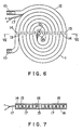
- FIGS. 6 and 7 illustrate still another embodiment of this invention, wherein a thermocouple element 18 is provided in a central portion of the heat sink 1.
- thermocouple element 18 is placed at a suitable position in a small void formed at the center of the spiral wound heat sink 1, and lead wires connected to the thermocouple element 18 are extended to be inserted between the portions of the pipe 12, forming the forward and return flow passages 13 and 14, during the pipe winding stage of the heat sink production.
- the remaining part of the small void is completely filled with a heat conductive material similar to that forming the cooling pipe 12, and then the heat sink 1 thus produced is slightly machined to provide smooth surfaces 16 contacting with the semiconductor elements.
- a protection member made of a synthetic resin may be provided around the thermocouple element.
- a recess or groove of a suitable size may be provided in the walls of the pipe portions between which the lead wired 17 are inserted.
- the lead wires 17 are extended between the spirally wound portions of the pipe 12, there is no necessity of forming a groove in a contacting surface of the pad 1 for accommodating the lead wires 17, and the cooling efficiency of the heat sink 1 can be improved in comparison with a type of heat sink having such a groove in the contacting surface thereof. Since the lead wires 17 are extended between the wound portions of the pipe 12 having a square or rectangular cross-section, there is no possibility of displacing the thermocouple 18 even in a case where the lead wires 17 are pulled during the production of the heat sink I, and the reliability in the operation of the thermocouple can be improved without increasing the production cost.
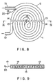
- FIGS. 8 and 9 illustrate still another embodiment of this invention wherein such terminals T are provided without requiring the machine screw and the like.
- a bare copper or aluminum wire 19 is inserted between the wound portions of the cooling pipe 12, and terminal 20 is secured to an outer end of the bare wire 19.
- the terminals 20 of the heat sinks inserted between the semiconductor elements can be used for connecting the anode side and cathode side of each element to the series connected resistor and capacitor as shown in FIG. 10.
- FIG. 12 illustrates a further embodiment of the invention wherein two heat sinks I, each constructed as in the case of the above described embodiment, are connected with each other.
- the semiconductor elements 2 are frequently connected in an anti-parallel manner as shown in FIG. 11.
- the embodiment shown in FIG. 12 may be used advantageously in consideration of the electric potential of each element, and since the number of connecting points is reduced, the possibility of leakage of the liquid coolant can be thereby reduced.
- a heat sink for semiconductor elements and the like which can reduce the thermal stress created in the element and the head loss caused in the heat sink. Furthermore, the thickness of the heat sink is reduced in comparison with the conventional heat sink because the block of heat conducting material through which a cooling passage is formed is not utilized, while the number of the spiral wound turns of the cooling pipe can be varied in accordance with the required diameter of the semiconductor element, and a heat sink of a high cooling effect, high reliability and highly economical in production can be thereby produced.
Landscapes
- Engineering & Computer Science (AREA)
- Physics & Mathematics (AREA)
- Thermal Sciences (AREA)
- Mechanical Engineering (AREA)
- General Engineering & Computer Science (AREA)
- Cooling Or The Like Of Semiconductors Or Solid State Devices (AREA)
Claims (9)
Applications Claiming Priority (2)
| Application Number | Priority Date | Filing Date | Title |
|---|---|---|---|
| JP60204428A JPH06101524B2 (ja) | 1985-09-18 | 1985-09-18 | 半導体素子用冷却体 |
| JP204428/85 | 1985-09-18 |
Publications (3)
| Publication Number | Publication Date |
|---|---|
| EP0219692A2 EP0219692A2 (fr) | 1987-04-29 |
| EP0219692A3 EP0219692A3 (en) | 1987-05-13 |
| EP0219692B1 true EP0219692B1 (fr) | 1989-11-23 |
Family
ID=16490373
Family Applications (1)
| Application Number | Title | Priority Date | Filing Date |
|---|---|---|---|
| EP86112859A Expired EP0219692B1 (fr) | 1985-09-18 | 1986-09-17 | Procédé pour la fabrication d'un refroidisseur et refroidisseur ainsi fabriqué |
Country Status (6)
| Country | Link |
|---|---|
| US (1) | US4747450A (fr) |
| EP (1) | EP0219692B1 (fr) |
| JP (1) | JPH06101524B2 (fr) |
| CN (1) | CN1010067B (fr) |
| CA (1) | CA1255811A (fr) |
| DE (1) | DE3667117D1 (fr) |
Families Citing this family (71)
| Publication number | Priority date | Publication date | Assignee | Title |
|---|---|---|---|---|
| FR2631165B1 (fr) * | 1988-05-05 | 1992-02-21 | Moulene Daniel | Support conditionneur de temperature pour petits objets tels que des composants semi-conducteurs et procede de regulation thermique utilisant ce support |
| US4883117A (en) * | 1988-07-20 | 1989-11-28 | Sundstrand Corporation | Swirl flow heat exchanger with reverse spiral configuration |
| US5077523A (en) * | 1989-11-03 | 1991-12-31 | John H. Blanz Company, Inc. | Cryogenic probe station having movable chuck accomodating variable thickness probe cards |
| US5160883A (en) * | 1989-11-03 | 1992-11-03 | John H. Blanz Company, Inc. | Test station having vibrationally stabilized X, Y and Z movable integrated circuit receiving support |
| US5166606A (en) * | 1989-11-03 | 1992-11-24 | John H. Blanz Company, Inc. | High efficiency cryogenic test station |
| US5098204A (en) * | 1989-11-03 | 1992-03-24 | John H. Blanz Company, Inc. | Load balanced planar bearing assembly especially for a cryogenic probe station |
| US5097207A (en) * | 1989-11-03 | 1992-03-17 | John H. Blanz Company, Inc. | Temperature stable cryogenic probe station |
| US5232047A (en) * | 1991-04-02 | 1993-08-03 | Microunity Systems Engineering, Inc. | Heat exchanger for solid-state electronic devices |
| US5906683A (en) * | 1996-04-16 | 1999-05-25 | Applied Materials, Inc. | Lid assembly for semiconductor processing chamber |
| US5826643A (en) | 1996-06-07 | 1998-10-27 | International Business Machines Corporation | Method of cooling electronic devices using a tube in plate heat sink |
| US6111749A (en) * | 1996-09-25 | 2000-08-29 | International Business Machines Corporation | Flexible cold plate having a one-piece coolant conduit and method employing same |
| US5920457A (en) * | 1996-09-25 | 1999-07-06 | International Business Machines Corporation | Apparatus for cooling electronic devices using a flexible coolant conduit |
| AU6683498A (en) | 1997-03-03 | 1998-09-22 | Medical Solutions, Inc. | Method and apparatus for pressure infusion and temperature control of infused liquids |
| US7090658B2 (en) * | 1997-03-03 | 2006-08-15 | Medical Solutions, Inc. | Temperature sensing device for selectively measuring temperature at desired locations along an intravenous fluid line |
| US7041941B2 (en) | 1997-04-07 | 2006-05-09 | Patented Medical Solutions, Llc | Medical item thermal treatment systems and method of monitoring medical items for compliance with prescribed requirements |
| US6467953B1 (en) | 1999-03-30 | 2002-10-22 | Medical Solutions, Inc. | Method and apparatus for monitoring temperature of intravenously delivered fluids and other medical items |
| US7276675B2 (en) | 1997-04-07 | 2007-10-02 | Patented Medical Solutions, Llc | Medical item thermal treatment systems and method of monitoring medical items for compliance with prescribed requirements |
| US6660974B2 (en) * | 1997-04-07 | 2003-12-09 | Medical Solutions, Inc. | Warming system and method for heating various items utilized in surgical procedures |
| CN1112626C (zh) * | 1998-06-24 | 2003-06-25 | 台达电子工业股份有限公司 | 改善散热方式的小型化的携带式电脑的电源供应系统 |
| WO2001002108A1 (fr) | 1999-07-06 | 2001-01-11 | Semitool, Inc. | Systeme de chauffage de fluides pour le traitement de materiaux semiconducteurs |
| US6536450B1 (en) * | 1999-07-07 | 2003-03-25 | Semitool, Inc. | Fluid heating system for processing semiconductor materials |
| US6226178B1 (en) | 1999-10-12 | 2001-05-01 | Dell Usa, L.P. | Apparatus for cooling a heat generating component in a computer |
| US6544085B1 (en) * | 1999-10-21 | 2003-04-08 | Bombardier Inc. | Watercraft having a closed coolant circulating system with a heat exchanger that constitutes an exterior surface of the hull |
| SE522799C2 (sv) * | 2000-02-23 | 2004-03-09 | Teracom Ab | Anordning för borttransport av värme från uppvärmda element samt ett förfarande för tillverkning av anordningen |
| SE0000587L (sv) * | 2000-02-23 | 2001-08-24 | Teracom Ab | Anordning för borttransport av värme från upphettade element och förfarande för att tillverka anordningen. |
| US6679316B1 (en) * | 2000-10-02 | 2004-01-20 | The United States Of America As Represented By The Secretary Of The Air Force | Passive thermal spreader and method |
| US7238171B2 (en) * | 2001-03-12 | 2007-07-03 | Medical Solutions, Inc. | Method and apparatus for controlling pressurized infusion and temperature of infused liquids |
| US7031602B2 (en) * | 2001-03-12 | 2006-04-18 | Patented Medical Solutions, Llc | Method and apparatus for controlling temperature of infused liquids |
| US6621071B2 (en) * | 2001-09-07 | 2003-09-16 | Raytheon Co. | Microelectronic system with integral cryocooler, and its fabrication and use |
| JP2003152376A (ja) * | 2001-11-12 | 2003-05-23 | Hitachi Ltd | 電子装置 |
| US8226605B2 (en) * | 2001-12-17 | 2012-07-24 | Medical Solutions, Inc. | Method and apparatus for heating solutions within intravenous lines to desired temperatures during infusion |
| JP4101511B2 (ja) * | 2001-12-27 | 2008-06-18 | 株式会社半導体エネルギー研究所 | 発光装置及びその作製方法 |
| US6892803B2 (en) * | 2002-11-19 | 2005-05-17 | Modine Manufacturing Company | High pressure heat exchanger |
| US6959758B2 (en) * | 2002-12-03 | 2005-11-01 | Modine Manufacturing Company | Serpentine tube, cross flow heat exchanger construction |
| KR100512261B1 (ko) * | 2003-06-25 | 2005-09-05 | 주식회사 좋은기술 | 반도체 냉각 유로 장치 |
| US7128025B1 (en) | 2003-10-24 | 2006-10-31 | Brp Us Inc. | Dual temperature closed loop cooling system |
| US7611504B1 (en) | 2004-03-09 | 2009-11-03 | Patented Medical Solutions Llc | Method and apparatus for facilitating injection of medication into an intravenous fluid line while maintaining sterility of infused fluids |
| US8709162B2 (en) * | 2005-08-16 | 2014-04-29 | Applied Materials, Inc. | Active cooling substrate support |
| US7740611B2 (en) | 2005-10-27 | 2010-06-22 | Patented Medical Solutions, Llc | Method and apparatus to indicate prior use of a medical item |
| US8487738B2 (en) * | 2006-03-20 | 2013-07-16 | Medical Solutions, Inc. | Method and apparatus for securely storing medical items within a thermal treatment system |
| US8226293B2 (en) | 2007-02-22 | 2012-07-24 | Medical Solutions, Inc. | Method and apparatus for measurement and control of temperature for infused liquids |
| EP2132580B1 (fr) * | 2007-04-05 | 2014-05-21 | AEHR Test Systems | Procédé de test d'un circuit microélectronique |
| US8000105B2 (en) * | 2008-07-14 | 2011-08-16 | International Business Machines Corporation | Tubular memory module |
| TW201036527A (en) * | 2009-03-19 | 2010-10-01 | Acbel Polytech Inc | Large-area liquid-cooled heat-dissipation device |
| CN101782339B (zh) * | 2010-03-09 | 2012-07-04 | 石家庄市石换换热环保有限公司 | 螺旋盘管式换热装置 |
| US8368208B2 (en) | 2010-10-01 | 2013-02-05 | Raytheon Company | Semiconductor cooling apparatus |
| CN102151818A (zh) * | 2011-01-31 | 2011-08-17 | 曾绍金 | 水冷铝块的设计和制造 |
| CN102244011A (zh) * | 2011-06-14 | 2011-11-16 | 东莞市永兴电子科技有限公司 | 水冷式液冷板的制作工艺 |
| US9211381B2 (en) | 2012-01-20 | 2015-12-15 | Medical Solutions, Inc. | Method and apparatus for controlling temperature of medical liquids |
| CN103307903A (zh) * | 2012-03-07 | 2013-09-18 | 晋惠冷却机械股份有限公司 | 冷却水塔的冷却管盘面螺旋圈绕法 |
| US9553038B2 (en) | 2012-04-02 | 2017-01-24 | Raytheon Company | Semiconductor cooling apparatus |
| US9472487B2 (en) | 2012-04-02 | 2016-10-18 | Raytheon Company | Flexible electronic package integrated heat exchanger with cold plate and risers |
| US9656029B2 (en) | 2013-02-15 | 2017-05-23 | Medical Solutions, Inc. | Plural medical item warming system and method for warming a plurality of medical items to desired temperatures |
| JP2014183072A (ja) * | 2013-03-18 | 2014-09-29 | Fujitsu Ltd | 電子機器及び受熱器 |
| CN104167397B (zh) * | 2013-05-17 | 2017-12-05 | 国家电网公司 | 一种集成散热晶闸管 |
| CN104464896A (zh) * | 2013-09-25 | 2015-03-25 | 金盘电气集团(上海)有限公司 | 带加强肋的空心导线 |
| AT516385B1 (de) * | 2015-06-23 | 2016-05-15 | Avl List Gmbh | Temperiereinheit für ein gasförmiges oder flüssiges Medium |
| CN106403655A (zh) * | 2015-07-31 | 2017-02-15 | 杭州三花家电热管理系统有限公司 | 一种换热器及其在系统中的应用 |
| CN105318767A (zh) * | 2015-08-15 | 2016-02-10 | 何家密 | 主动式热交换以及其应用 |
| GB2544979A (en) * | 2015-12-01 | 2017-06-07 | Rolls Royce Plc | A heat sink of source apparatus and method |
| CN107178446A (zh) * | 2016-03-11 | 2017-09-19 | 日立汽车系统(苏州)有限公司 | 具有egr系统的发动机系统、egr气体的除湿方法 |
| PL3622226T3 (pl) * | 2017-05-10 | 2022-03-07 | Gea Food Solutions Weert B.V. | Ulepszone środki grzejne dla owijarki przepływowej |
| FR3068773B1 (fr) * | 2017-07-06 | 2019-09-27 | Valeo Systemes Thermiques | Dispositif de regulation thermique de modules de batterie |
| CN107860247B (zh) * | 2017-10-10 | 2019-12-27 | 深圳航天东方红海特卫星有限公司 | 一种换热槽道螺旋式分布的扩热板 |
| US11316216B2 (en) | 2018-10-24 | 2022-04-26 | Dana Canada Corporation | Modular heat exchangers for battery thermal modulation |
| CN112880454A (zh) * | 2019-11-29 | 2021-06-01 | 上海微电子装备(集团)股份有限公司 | 一种换热结构及半导体换热装置 |
| DE102020207713A1 (de) | 2020-06-22 | 2021-12-23 | Zf Friedrichshafen Ag | Kühlgeometrie für Leistungselektroniken |
| US11915997B2 (en) * | 2020-06-24 | 2024-02-27 | Micron Technology, Inc. | Thermal management of GPU-HBM package by microchannel integrated substrate |
| CN111843605B (zh) * | 2020-07-20 | 2022-04-29 | 湖南中大创远数控装备有限公司 | 一种主轴冷却机构以及机床 |
| KR20220027562A (ko) * | 2020-08-27 | 2022-03-08 | 엘지전자 주식회사 | 열교환기 |
| KR102728811B1 (ko) * | 2021-11-23 | 2024-11-13 | 피에스케이 주식회사 | 지지 유닛, 그리고 이를 포함하는 기판 처리 장치 |
Family Cites Families (17)
| Publication number | Priority date | Publication date | Assignee | Title |
|---|---|---|---|---|
| US665573A (en) * | 1900-10-26 | 1901-01-08 | Gen Electric | Transformer. |
| US1571929A (en) * | 1922-05-18 | 1926-02-09 | Wilhelm B Bronander | Die holder |
| US1847573A (en) * | 1930-03-12 | 1932-03-01 | Commercial Iron Works | Platen for presses with heating coils |
| US2506118A (en) * | 1947-01-13 | 1950-05-02 | Merritt I Taylor | Cluster controller |
| US3213929A (en) * | 1962-02-12 | 1965-10-26 | Varian Associates | Temperature control system |
| FR1436064A (fr) * | 1965-03-12 | 1966-04-22 | Radiotechnique | élément d'évacuation de chaleur pour dispositif semi-conducteur de puissance |
| DE1514679A1 (de) * | 1966-01-29 | 1969-06-19 | Siemens Ag | Anordnung zur Fluessigkeitskuehlung einer Gleichrichterzelle |
| DE2023598C3 (de) * | 1970-05-14 | 1976-01-02 | Bosch-Siemens Hausgeraete Gmbh, 7000 Stuttgart | Elektrischer Durchlauferhitzer für Kaffeemaschinen |
| DE2124303A1 (fr) * | 1971-05-17 | 1972-10-26 | ||
| US4010489A (en) * | 1975-05-19 | 1977-03-01 | General Motors Corporation | High power semiconductor device cooling apparatus and method |
| US4287724A (en) * | 1979-12-17 | 1981-09-08 | Morehouse Industries, Inc. | Air chiller/drier |
| DE3039693A1 (de) * | 1980-10-21 | 1982-04-29 | Gunnar 7770 Überlingen Larsson | Verfahren und vorrichtung zum herstellen von waermetauscherelementen, wie heizkoerpersegmenten, kuehlschlangen etc. |
| CH651994A5 (de) * | 1981-03-10 | 1985-10-15 | Injecta Ag | Fluessigkeitsgekuehlte elektrische baugruppe sowie verfahren zu deren herstellung. |
| SE467321B (sv) * | 1982-02-08 | 1992-06-29 | Elge Ab | Spiralvaermevaexlare daer roeren har aatminstone delvis plana sidoytor |
| FR2524760B1 (fr) * | 1982-03-30 | 1986-10-10 | Auxilec | Piece de maintien pour semiconducteur, et dispositif de puissance a semiconducteur comportant une telle piece |
| CS233062B1 (en) * | 1983-04-20 | 1985-02-14 | Vladimir Motycka | Liquid cooler for power semiconductor elements cooling |
| JPS60113448A (ja) * | 1983-11-02 | 1985-06-19 | ベー・ベー・ツエー・アクチエンゲゼルシヤフト・ブラウン・ボヴエリ・ウント・コンパニイ | 電力半導体素子の液冷のための冷却体 |
-
1985
- 1985-09-18 JP JP60204428A patent/JPH06101524B2/ja not_active Expired - Fee Related
-
1986
- 1986-09-17 EP EP86112859A patent/EP0219692B1/fr not_active Expired
- 1986-09-17 DE DE8686112859T patent/DE3667117D1/de not_active Expired
- 1986-09-17 CN CN86107015A patent/CN1010067B/zh not_active Expired
- 1986-09-17 CA CA000518362A patent/CA1255811A/fr not_active Expired
- 1986-09-18 US US06/908,773 patent/US4747450A/en not_active Expired - Lifetime
Also Published As
| Publication number | Publication date |
|---|---|
| DE3667117D1 (en) | 1989-12-28 |
| EP0219692A3 (en) | 1987-05-13 |
| JPS6265444A (ja) | 1987-03-24 |
| CN86107015A (zh) | 1987-11-25 |
| JPH06101524B2 (ja) | 1994-12-12 |
| EP0219692A2 (fr) | 1987-04-29 |
| CN1010067B (zh) | 1990-10-17 |
| US4747450A (en) | 1988-05-31 |
| CA1255811A (fr) | 1989-06-13 |
Similar Documents
| Publication | Publication Date | Title |
|---|---|---|
| US4747450A (en) | Method for producing heat sink and heat sink thus produced | |
| US6825583B2 (en) | Linear motor including cooling system | |
| EP0603860B1 (fr) | Système de refroidissement pour modules de puissance | |
| US2815472A (en) | Rectifier unit | |
| EP1336204B1 (fr) | Module thermoelectrique muni d'un echangeur de chaleur integre et procede d'utilisation | |
| US20210243923A1 (en) | Power module assembly | |
| JPH10106521A (ja) | 蓄電池電源装置 | |
| WO1986007193A1 (fr) | Pile refroidie de semiconducteurs electriquement isoles | |
| KR19990072177A (ko) | 전자전력모듈및다수의상기모듈들을포함하는전자전력시스템 | |
| JPS6114105A (ja) | 冷却式内部電極を有する管状オゾン発生器 | |
| US3983427A (en) | Superconducting winding with grooved spacing elements | |
| US3098941A (en) | Dynamoelectric machine winding with edge-standing fluid-cooled conductors | |
| CN110911130B (zh) | 一种开关电源结构 | |
| JP3112614B2 (ja) | 電力半導体素子の冷却ブロック | |
| JP3210199B2 (ja) | 平形半導体素子の冷却体 | |
| EP0401743A1 (fr) | Dispositif de refroidissement par caloduc pour semi-conducteur | |
| US2718615A (en) | Liquid cooling of dry disc rectifiers | |
| CN1011563B (zh) | 具有多个要冷却的电气元件的电路装置 | |
| JPS63262861A (ja) | 半導体素子用冷却体 | |
| JP7461435B2 (ja) | リニアモーター | |
| GB2126059A (en) | Multilayer cylindrical induction coil | |
| JPH0610696Y2 (ja) | 半導体スタック | |
| JP4293090B2 (ja) | 冷却装置 | |
| SU1713020A1 (ru) | Ротор электрической машины со сверхпроводниковой обмоткой возбуждени | |
| JPS58135657A (ja) | 半導体装置 |
Legal Events
| Date | Code | Title | Description |
|---|---|---|---|
| PUAI | Public reference made under article 153(3) epc to a published international application that has entered the european phase |
Free format text: ORIGINAL CODE: 0009012 |
|
| PUAL | Search report despatched |
Free format text: ORIGINAL CODE: 0009013 |
|
| 17P | Request for examination filed |
Effective date: 19861010 |
|
| AK | Designated contracting states |
Kind code of ref document: A2 Designated state(s): CH DE LI SE |
|
| AK | Designated contracting states |
Kind code of ref document: A3 Designated state(s): CH DE LI SE |
|
| 17Q | First examination report despatched |
Effective date: 19881229 |
|
| GRAA | (expected) grant |
Free format text: ORIGINAL CODE: 0009210 |
|
| AK | Designated contracting states |
Kind code of ref document: B1 Designated state(s): CH DE LI SE |
|
| REF | Corresponds to: |
Ref document number: 3667117 Country of ref document: DE Date of ref document: 19891228 |
|
| PLBE | No opposition filed within time limit |
Free format text: ORIGINAL CODE: 0009261 |
|
| STAA | Information on the status of an ep patent application or granted ep patent |
Free format text: STATUS: NO OPPOSITION FILED WITHIN TIME LIMIT |
|
| 26N | No opposition filed | ||
| PGFP | Annual fee paid to national office [announced via postgrant information from national office to epo] |
Ref country code: CH Payment date: 19940914 Year of fee payment: 9 |
|
| EAL | Se: european patent in force in sweden |
Ref document number: 86112859.3 |
|
| PG25 | Lapsed in a contracting state [announced via postgrant information from national office to epo] |
Ref country code: LI Effective date: 19950930 Ref country code: CH Effective date: 19950930 |
|
| REG | Reference to a national code |
Ref country code: CH Ref legal event code: PL |
|
| PGFP | Annual fee paid to national office [announced via postgrant information from national office to epo] |
Ref country code: SE Payment date: 19990907 Year of fee payment: 14 |
|
| PGFP | Annual fee paid to national office [announced via postgrant information from national office to epo] |
Ref country code: DE Payment date: 19990927 Year of fee payment: 14 |
|
| PG25 | Lapsed in a contracting state [announced via postgrant information from national office to epo] |
Ref country code: SE Free format text: THE PATENT HAS BEEN ANNULLED BY A DECISION OF A NATIONAL AUTHORITY Effective date: 20000929 |
|
| EUG | Se: european patent has lapsed |
Ref document number: 86112859.3 |
|
| PG25 | Lapsed in a contracting state [announced via postgrant information from national office to epo] |
Ref country code: DE Free format text: LAPSE BECAUSE OF NON-PAYMENT OF DUE FEES Effective date: 20010601 |