EP0219693B1 - Procédé pour actionner un pulvérisateur à ultrasons afin de pulvériser des fluides - Google Patents
Procédé pour actionner un pulvérisateur à ultrasons afin de pulvériser des fluides Download PDFInfo
- Publication number
- EP0219693B1 EP0219693B1 EP86112865A EP86112865A EP0219693B1 EP 0219693 B1 EP0219693 B1 EP 0219693B1 EP 86112865 A EP86112865 A EP 86112865A EP 86112865 A EP86112865 A EP 86112865A EP 0219693 B1 EP0219693 B1 EP 0219693B1
- Authority
- EP
- European Patent Office
- Prior art keywords
- frequency
- current
- burst
- atomizer
- ultrasonic
- Prior art date
- Legal status (The legal status is an assumption and is not a legal conclusion. Google has not performed a legal analysis and makes no representation as to the accuracy of the status listed.)
- Expired - Lifetime
Links
- 238000000034 method Methods 0.000 title claims description 21
- 230000015654 memory Effects 0.000 claims abstract description 15
- 239000007788 liquid Substances 0.000 claims description 22
- 238000005259 measurement Methods 0.000 claims description 15
- 230000001419 dependent effect Effects 0.000 claims description 8
- 238000000889 atomisation Methods 0.000 claims description 5
- 238000004519 manufacturing process Methods 0.000 claims description 4
- 230000005284 excitation Effects 0.000 claims description 3
- 238000009688 liquid atomisation Methods 0.000 claims description 2
- 238000009736 wetting Methods 0.000 claims description 2
- 230000002277 temperature effect Effects 0.000 claims 1
- 238000005070 sampling Methods 0.000 abstract 1
- 238000010586 diagram Methods 0.000 description 7
- 238000004378 air conditioning Methods 0.000 description 2
- 230000006378 damage Effects 0.000 description 2
- 238000013461 design Methods 0.000 description 2
- 230000000694 effects Effects 0.000 description 2
- 238000010438 heat treatment Methods 0.000 description 2
- 238000012546 transfer Methods 0.000 description 2
- 230000015572 biosynthetic process Effects 0.000 description 1
- 239000000919 ceramic Substances 0.000 description 1
- 239000011248 coating agent Substances 0.000 description 1
- 238000000576 coating method Methods 0.000 description 1
- 150000001875 compounds Chemical class 0.000 description 1
- 239000002537 cosmetic Substances 0.000 description 1
- 239000002781 deodorant agent Substances 0.000 description 1
- 239000003599 detergent Substances 0.000 description 1
- 238000011161 development Methods 0.000 description 1
- 230000018109 developmental process Effects 0.000 description 1
- 239000002283 diesel fuel Substances 0.000 description 1
- 239000003814 drug Substances 0.000 description 1
- 229940079593 drug Drugs 0.000 description 1
- 239000000446 fuel Substances 0.000 description 1
- 230000006870 function Effects 0.000 description 1
- 239000008266 hair spray Substances 0.000 description 1
- 238000002483 medication Methods 0.000 description 1
- 238000012544 monitoring process Methods 0.000 description 1
- 239000002304 perfume Substances 0.000 description 1
- 238000012545 processing Methods 0.000 description 1
- 230000001105 regulatory effect Effects 0.000 description 1
- 230000000717 retained effect Effects 0.000 description 1
- 239000002904 solvent Substances 0.000 description 1
- 230000001052 transient effect Effects 0.000 description 1
- 230000007704 transition Effects 0.000 description 1
- XLYOFNOQVPJJNP-UHFFFAOYSA-N water Substances O XLYOFNOQVPJJNP-UHFFFAOYSA-N 0.000 description 1
Images


Classifications
-
- B—PERFORMING OPERATIONS; TRANSPORTING
- B05—SPRAYING OR ATOMISING IN GENERAL; APPLYING FLUENT MATERIALS TO SURFACES, IN GENERAL
- B05B—SPRAYING APPARATUS; ATOMISING APPARATUS; NOZZLES
- B05B17/00—Apparatus for spraying or atomising liquids or other fluent materials, not covered by the preceding groups
- B05B17/04—Apparatus for spraying or atomising liquids or other fluent materials, not covered by the preceding groups operating with special methods
- B05B17/06—Apparatus for spraying or atomising liquids or other fluent materials, not covered by the preceding groups operating with special methods using ultrasonic or other kinds of vibrations
- B05B17/0607—Apparatus for spraying or atomising liquids or other fluent materials, not covered by the preceding groups operating with special methods using ultrasonic or other kinds of vibrations generated by electrical means, e.g. piezoelectric transducers
- B05B17/0623—Apparatus for spraying or atomising liquids or other fluent materials, not covered by the preceding groups operating with special methods using ultrasonic or other kinds of vibrations generated by electrical means, e.g. piezoelectric transducers coupled with a vibrating horn
-
- B—PERFORMING OPERATIONS; TRANSPORTING
- B05—SPRAYING OR ATOMISING IN GENERAL; APPLYING FLUENT MATERIALS TO SURFACES, IN GENERAL
- B05B—SPRAYING APPARATUS; ATOMISING APPARATUS; NOZZLES
- B05B12/00—Arrangements for controlling delivery; Arrangements for controlling the spray area
- B05B12/08—Arrangements for controlling delivery; Arrangements for controlling the spray area responsive to condition of liquid or other fluent material to be discharged, of ambient medium or of target ; responsive to condition of spray devices or of supply means, e.g. pipes, pumps or their drive means
-
- B—PERFORMING OPERATIONS; TRANSPORTING
- B05—SPRAYING OR ATOMISING IN GENERAL; APPLYING FLUENT MATERIALS TO SURFACES, IN GENERAL
- B05B—SPRAYING APPARATUS; ATOMISING APPARATUS; NOZZLES
- B05B15/00—Details of spraying plant or spraying apparatus not otherwise provided for; Accessories
- B05B15/14—Arrangements for preventing or controlling structural damage to spraying apparatus or its outlets, e.g. for breaking at desired places; Arrangements for handling or replacing damaged parts
-
- B—PERFORMING OPERATIONS; TRANSPORTING
- B05—SPRAYING OR ATOMISING IN GENERAL; APPLYING FLUENT MATERIALS TO SURFACES, IN GENERAL
- B05B—SPRAYING APPARATUS; ATOMISING APPARATUS; NOZZLES
- B05B17/00—Apparatus for spraying or atomising liquids or other fluent materials, not covered by the preceding groups
- B05B17/04—Apparatus for spraying or atomising liquids or other fluent materials, not covered by the preceding groups operating with special methods
- B05B17/06—Apparatus for spraying or atomising liquids or other fluent materials, not covered by the preceding groups operating with special methods using ultrasonic or other kinds of vibrations
- B05B17/0607—Apparatus for spraying or atomising liquids or other fluent materials, not covered by the preceding groups operating with special methods using ultrasonic or other kinds of vibrations generated by electrical means, e.g. piezoelectric transducers
- B05B17/0623—Apparatus for spraying or atomising liquids or other fluent materials, not covered by the preceding groups operating with special methods using ultrasonic or other kinds of vibrations generated by electrical means, e.g. piezoelectric transducers coupled with a vibrating horn
- B05B17/063—Apparatus for spraying or atomising liquids or other fluent materials, not covered by the preceding groups operating with special methods using ultrasonic or other kinds of vibrations generated by electrical means, e.g. piezoelectric transducers coupled with a vibrating horn having an internal channel for supplying the liquid or other fluent material
-
- B—PERFORMING OPERATIONS; TRANSPORTING
- B05—SPRAYING OR ATOMISING IN GENERAL; APPLYING FLUENT MATERIALS TO SURFACES, IN GENERAL
- B05B—SPRAYING APPARATUS; ATOMISING APPARATUS; NOZZLES
- B05B17/00—Apparatus for spraying or atomising liquids or other fluent materials, not covered by the preceding groups
- B05B17/04—Apparatus for spraying or atomising liquids or other fluent materials, not covered by the preceding groups operating with special methods
- B05B17/06—Apparatus for spraying or atomising liquids or other fluent materials, not covered by the preceding groups operating with special methods using ultrasonic or other kinds of vibrations
- B05B17/0607—Apparatus for spraying or atomising liquids or other fluent materials, not covered by the preceding groups operating with special methods using ultrasonic or other kinds of vibrations generated by electrical means, e.g. piezoelectric transducers
- B05B17/0653—Details
- B05B17/0669—Excitation frequencies
-
- B—PERFORMING OPERATIONS; TRANSPORTING
- B06—GENERATING OR TRANSMITTING MECHANICAL VIBRATIONS IN GENERAL
- B06B—METHODS OR APPARATUS FOR GENERATING OR TRANSMITTING MECHANICAL VIBRATIONS OF INFRASONIC, SONIC, OR ULTRASONIC FREQUENCY, e.g. FOR PERFORMING MECHANICAL WORK IN GENERAL
- B06B1/00—Methods or apparatus for generating mechanical vibrations of infrasonic, sonic, or ultrasonic frequency
- B06B1/02—Methods or apparatus for generating mechanical vibrations of infrasonic, sonic, or ultrasonic frequency making use of electrical energy
- B06B1/0207—Driving circuits
- B06B1/0223—Driving circuits for generating signals continuous in time
- B06B1/0238—Driving circuits for generating signals continuous in time of a single frequency, e.g. a sine-wave
- B06B1/0246—Driving circuits for generating signals continuous in time of a single frequency, e.g. a sine-wave with a feedback signal
- B06B1/0253—Driving circuits for generating signals continuous in time of a single frequency, e.g. a sine-wave with a feedback signal taken directly from the generator circuit
-
- B—PERFORMING OPERATIONS; TRANSPORTING
- B06—GENERATING OR TRANSMITTING MECHANICAL VIBRATIONS IN GENERAL
- B06B—METHODS OR APPARATUS FOR GENERATING OR TRANSMITTING MECHANICAL VIBRATIONS OF INFRASONIC, SONIC, OR ULTRASONIC FREQUENCY, e.g. FOR PERFORMING MECHANICAL WORK IN GENERAL
- B06B2201/00—Indexing scheme associated with B06B1/0207 for details covered by B06B1/0207 but not provided for in any of its subgroups
- B06B2201/50—Application to a particular transducer type
- B06B2201/55—Piezoelectric transducer
-
- B—PERFORMING OPERATIONS; TRANSPORTING
- B06—GENERATING OR TRANSMITTING MECHANICAL VIBRATIONS IN GENERAL
- B06B—METHODS OR APPARATUS FOR GENERATING OR TRANSMITTING MECHANICAL VIBRATIONS OF INFRASONIC, SONIC, OR ULTRASONIC FREQUENCY, e.g. FOR PERFORMING MECHANICAL WORK IN GENERAL
- B06B2201/00—Indexing scheme associated with B06B1/0207 for details covered by B06B1/0207 but not provided for in any of its subgroups
- B06B2201/70—Specific application
- B06B2201/77—Atomizers
Definitions
- the invention relates to a method according to the preamble of patent claim 1.
- a method for operating an ultrasonic oscillator for liquid atomization is known, which is excited by burst pulses at the operating frequency and, on average, is sufficient for the set amount of liquid at the power supplied.
- the respective peak performance is so high that an excess amount of liquid can be shaken off for a short time (DE-OS 33 14 609).
- the operating frequency is manually adjusted to the ultrasonic transducer in the manufacturing plant.
- the ultrasonic liquid atomizers with manufacturing tolerances therefore always have somewhat different working frequencies.
- the ultrasonic transducers can therefore not be replaced without renewed coordination.
- the object of the invention is to design an ultrasonic liquid atomizer and a method for its operation which enables reliable atomization with continuous automatic frequency tuning and automatic shaking off of a flooded atomizing plate. Furthermore, a lower power consumption of the electronics, a low temperature load and a high atomization rate should be guaranteed. Automatic temperature monitoring should be integrable.
- Claims 10 and 11 relate to a piezoelectric ultrasonic liquid atomizer for carrying out the method.
- a current measurement is made during the period of a burst pulse t1 after a delay time t3 for a period of time t4, the sum of the delay time t3 and the period of time t4 being not greater than the duration of the burst pulse t1, the current measurement values two successive burst pulses compared with each other in a measured value comparator, the comparison signal of the measured value comparator is fed to a frequency control, it is achieved that measurements are made at comparable time intervals of the burst pulse and the frequency detuning cannot have a falsifying effect on the automatic frequency compensation due to the temporary flooding of the oscillating system.
- the range of the automatic frequency adjustment is so limited that the circuit can only be set within the frequency band that can be used for atomization, that is to say the different wetting of the operating frequency and the maximum possible fluctuations in operating frequency due to manufacturing tolerances of the ultrasonic atomizer,
- the optimum working frequency of the ultrasonic atomizer can be found quickly, since only a predetermined frequency range in which the working frequency of the ultrasonic liquid atomizer lies passes through must become.
- operational safety is increased because it is no longer possible to lock onto a different frequency, for example the compound resonance frequency of the ultrasonic atomizer - which would lead to the destruction of the atomizer.
- FIG. 5 shows an ultrasonic liquid atomizer 3 with a piezoceramic 4, a coupled amplitude transformer 5 and an atomizer plate 6.
- a tube 7 integrated in the atomizer cone 4, 5 serves to supply liquid.
- the associated electronics are designated by 8.
- FIG. 6 shows another ultrasonic liquid atomizer which carries a temperature-dependent resistor 10 applied to the piezoceramic 9.
- the associated electronics are designated 11 in this figure.
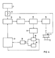
- FIG. 4 shows a block diagram of the electronics 8 and 11.
- a power supply 12 an on-off switch, 13 a burst and frequency generation, 14 a preamplifier, 15 an output stage, and 16 on Transmitter, with 3 of the ultrasonic liquid atomizers, with 2 a temperature-dependent resistor, with 17 a current measuring stage, with 18 and 19 measured value memories I and II, with 20 a measured value comparator, with 21 denotes a frequency control.
- the liquid atomizer 3 is excited by the burst and frequency generation 13 via the pre- and final stage with a burst, a briefly applied AC voltage.
- the burst frequency can be regulated using the method according to the invention. This regulation takes place via a current measurement.
- a temperature-dependent resistor 2 is applied to the ultrasonic liquid atomizer 3. This temperature-dependent resistor 2 switches off the electronics 11 at impermissible temperatures.
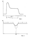
- t 1 shows a diagram of the current profile in the output stage 15 over time or the voltage drop caused by it to a resistor, not shown here.
- the duration of the burst pulse, i.e. the excitation frequency switched on briefly with different power is denoted by t 1. No measurement takes place during the period t3. Only the measurement results obtained during the period t4 are used for frequency compensation.
- Figure 2 shows a diagram of the voltage curve as a function of frequency, where f1 is the working frequency or the working point of the liquid atomizer flooded or damped, while f2 is the working point or the working frequency of the undamped liquid atomizer 3.
- Area A represents the frequency range that cannot be used for atomization.
- the time course of the frequency tuning is plotted in FIG. 3 in five diagrams (a) to (e).
- the time period t 1 for the switch-on time and t 2 for the switch-off time of the burst pulse is entered.
- the delay time t3 during which no measurement is made is entered.
- the current measurement is entered after t3.
- the time t5 for the formation of the counter signal to be stored is entered. This time period t5 follows the burst pulse in terms of time.
- the time period t5 is followed by the time period t6 for the transfer of the counter signal corresponding to the measured value for the current into the measured value memory 18 and the measured value transfer from the measured value memory 18 into the measured value memory 19.
- the ultrasonic atomizer 3 is excited with a burst pulse, the pulse duration of which is denoted by t 1 in FIGS. 1 and 3.
- the ultrasonic atomizer 3 then swings freely with the time period t2 before the next burst pulse occurs.
- a voltage proportional to the current through the output stage 15 is converted into a measuring signal.
- part t3 of the current-proportional signal is hidden and only the measurement signal present during the period t4 is converted and stored in the measured value memory 18.
- the measured value previously stored in the measured value memory 18 is transferred to the measured value memory 19.
- the current measured value newly recorded in the measured value memory 18 is then compared by the measured value comparator 20 with the previous current measured value stored in the measured value memory 19.
- the signal corresponding to the comparison value and exceeding a threshold value at the output of the measured value comparator is applied to the frequency controller 21.
- the excitation frequency of the burst pulse is increased by the frequency control by one step per burst pulse. This can be the case, for example, when the circuit is started when the optimal operating frequency is sought.
- the frequency is reduced by one step per burst pulse. If the difference between the current measured values lies within the threshold value range, the frequency that was decisive for the previous burst is retained.
- the working frequency of the electronics is forcibly reduced by one step after a corresponding period of time t7 (FIG. 4).
- the dependence of the current through the output stage shown in FIG. 2 (this is proportional to the current through the ultrasonic oscillator) on the frequency illustrates the effect according to the invention, according to which the working frequency of the ultrasonic atomizer can be found very quickly and it does not matter, whether it is damped (flooded atomizing plate) or vibrates freely.
- the search direction preferably goes from low to high frequencies.
- the transition of the atomizer from the strongly damped (flooded) to the weakly damped (atomizing) state - combined with an increase in the working frequency of the ultrasonic atomizer - also takes place very quickly.
- Another advantage is that after finding the optimal atomizer operating frequency, the circuit oscillates closely around the optimal operating point. In areas A (FIG. 2) outside of the optimal operating points, appropriate circuit measures are used to predefine a constant current measurement value, from which the circuit can quickly snap to the operating frequency of the ultrasonic atomizer.
- the method according to the invention is particularly suitable for operating a piezoelectric ultrasonic atomizer with a piezoceramic and an amplitude transformer an atomizing plate (see Figure 5).
- a temperature-dependent resistor to the ceramic of the ultrasonic atomizer (FIG. 6). If, for example, an inadmissibly high temperature would occur on the ultrasonic atomizer as a result of running dry, the electronics switch off the output stage until the ultrasonic atomizer has cooled down again to a permissible temperature.
- Ultrasonic liquid atomizers working according to the method of the invention are particularly suitable for atomizing fuels such as diesel oil and petrol for burners, generators, auxiliary heaters and for atomizing cosmetics such as hairspray, deodorants and perfume, detergents, medications for inhalation purposes, solvents and water, for example in humidifiers, small climate chambers, air conditioning systems and terrariums as well as for use in systems for coating, humidification and air conditioning.
- fuels such as diesel oil and petrol for burners, generators, auxiliary heaters and for atomizing cosmetics such as hairspray, deodorants and perfume, detergents, medications for inhalation purposes, solvents and water, for example in humidifiers, small climate chambers, air conditioning systems and terrariums as well as for use in systems for coating, humidification and air conditioning.
Landscapes
- Engineering & Computer Science (AREA)
- Mechanical Engineering (AREA)
- Special Spraying Apparatus (AREA)
- Apparatuses For Generation Of Mechanical Vibrations (AREA)
Claims (11)
- Procédé pour faire fonctionner un pulvérisateur à ultrasons (3) excité à la fréquence de service par des impulsions en rafale pour pulvériser un liquide, avec un réglage automatique de la fréquence de service, caractérisé par le fait que pour le réglage automatique de la fréquence de service, on effectue une mesure du courant pendant la durée t₁ d'une impulsion de rafale au bout d'un retard t₃ et pendant un intervalle de temps t₄, la somme du retard t₃ et de l'intervalle de temps t₄ n'étant pas supérieure à la durée de l'impulsion t₁ de rafale, on compare les valeurs de mesure de courant de deux impulsions successives de rafale entre elles dans un comparateur de valeurs de mesure (20) et on envoie le signal de comparaison du comparateur de valeurs de mesure à une unité (21) de commande de la fréquence, et que la plage de réglage automatique de la fréquence est limitée de sorte que le circuit peut être réglé ou accroché uniquement à l'intérieur de la bande de fréquences utilisable pour la pulvérisation -c'est-à-dire dans la plage de variation de la fréquence de service (3), qui est possible au maximum en raison de tolérances de fabrication du pulvérisateur à ultrasons, d'un mouillage variable de ce dernier et d'influences de température.
- Procédé suivant la revendication 1, caractérisé par le fait que le réglage automatique de la fréquence du pulvérisateur à ultrasons est exécutée depuis la fréquence la plus faible en direction de la fréquence la plus élevée et/ou depuis la fréquence la plus élevée en direction de la fréquence la plus faible.
- Procédé suivant la revendication 1, caractérisé par le fait que le transfert de la valeur de mesure du courant s'effectue pendant l'intervalle de temps t₆ entre deux impulsions successives de rafale.
- Procédé suivant la revendication 3, caractérisé par le fait que, pour la comparaison des deux mesures des valeurs de courant, on utilise un circuit à valeur de seuil.
- Procédé suivant la revendication 4, caractérisé par le fait que la valeur de seuil de courant du circuit à valeur de seuil est inférieure à la différence de courant, qui apparaît entre un pulvérisateur (3) amorti et un pulvérisateur (3) oscillant d'une manière non amortie.
- Procédé suivant la revendication 4, caractérisé par le fait que la valeur de seuil pour les valeurs de mesure du courant est inférieure à la différence des limites de la plage de fréquences.
- Procédé suivant la revendication 4, caractérisé par le fait qu'une gamme déterminée de fréquences de travail est prédéterminée et qu'aucune différence mesurable de courant n'apparaît à l'extérieur de cette zone.
- Procédé suivant les revendications 1 et 2, caractérisé par le fait qu'après un intervalle de temps t7, le circuit exécute un pas dans le sens de la recherche, sans influer ce sens.
- Procédé suivant la revendication 1, caractérisé par le fait que le pulvérisateur à ultrasons comporte une résistance (2) qui dépend de la température.
- Pulvérisateur piézoélectrique de liquide à ultrasons pour la mise en oeuvre du procédé suivant une ou plusieurs des revendications 1 à 9, caractérisé par le fait que la piézocéramique (4,9) est raccordée par l'intermédiaire d'un étage final (15) à une unité (13) de production de la fréquence de rafale, et que l'étage final est raccordé à une unité (21) de commande de la fréquence de rafale par l'intermédiaire de deux mémoires de valeurs de mesure (18,19) pour le courant, au moyen de la piézocéramique, pendant deux impulsions successives de rafale, et d'un comparateur de valeurs de mesure (20).
- Pulvérisateur piézoélectrique de liquide à ultrasons suivant la revendication 10, caractérisé par le fait qu'une résistance (10), qui dépend de la température, est appliquée à la piézocéramique (9) et est raccordée à l'unité électronique d'excitation (11), dans le but d'interrompre le fonctionnement de cette dernière lors du dépassement d'une température prédéterminée.
Priority Applications (1)
| Application Number | Priority Date | Filing Date | Title |
|---|---|---|---|
| AT86112865T ATE68111T1 (de) | 1985-09-30 | 1986-09-17 | Verfahren zum betrieb eines ultraschallzerstaeubers zur fluessigkeitszerstaeubung. |
Applications Claiming Priority (2)
| Application Number | Priority Date | Filing Date | Title |
|---|---|---|---|
| DE3534853 | 1985-09-30 | ||
| DE19853534853 DE3534853A1 (de) | 1985-09-30 | 1985-09-30 | Verfahren zum betrieb eines ultraschallzerstaeubers zur fluessigkeitszerstaeubung |
Publications (2)
| Publication Number | Publication Date |
|---|---|
| EP0219693A1 EP0219693A1 (fr) | 1987-04-29 |
| EP0219693B1 true EP0219693B1 (fr) | 1991-10-09 |
Family
ID=6282366
Family Applications (1)
| Application Number | Title | Priority Date | Filing Date |
|---|---|---|---|
| EP86112865A Expired - Lifetime EP0219693B1 (fr) | 1985-09-30 | 1986-09-17 | Procédé pour actionner un pulvérisateur à ultrasons afin de pulvériser des fluides |
Country Status (4)
| Country | Link |
|---|---|
| US (1) | US4689515A (fr) |
| EP (1) | EP0219693B1 (fr) |
| AT (1) | ATE68111T1 (fr) |
| DE (2) | DE3534853A1 (fr) |
Families Citing this family (43)
| Publication number | Priority date | Publication date | Assignee | Title |
|---|---|---|---|---|
| JPS60222552A (ja) * | 1984-04-19 | 1985-11-07 | Toa Nenryo Kogyo Kk | 超音波噴射方法 |
| JPS6338193A (ja) * | 1986-08-01 | 1988-02-18 | Toa Nenryo Kogyo Kk | 超音波振動子ホ−ン |
| US4799622A (en) * | 1986-08-05 | 1989-01-24 | Tao Nenryo Kogyo Kabushiki Kaisha | Ultrasonic atomizing apparatus |
| KR900007413B1 (ko) * | 1986-08-26 | 1990-10-08 | 마쯔시다덴기산교 가부시기가이샤 | 초음파 모우터구동 방법 |
| CH672894A5 (fr) * | 1987-09-14 | 1990-01-15 | Undatim Ultrasonics | |
| US4966131A (en) * | 1988-02-09 | 1990-10-30 | Mettler Electronics Corp. | Ultrasound power generating system with sampled-data frequency control |
| US5095890A (en) * | 1988-02-09 | 1992-03-17 | Mettler Electronics Corp. | Method for sampled data frequency control of an ultrasound power generating system |
| US5113116A (en) * | 1989-10-05 | 1992-05-12 | Firma J. Eberspacher | Circuit arrangement for accurately and effectively driving an ultrasonic transducer |
| JPH03161083A (ja) * | 1989-11-17 | 1991-07-11 | Aisin Seiki Co Ltd | 圧電振動子の駆動装置および該駆動装置を使用した水滴除去装置 |
| GB9226474D0 (en) * | 1992-12-18 | 1993-02-10 | Ici Plc | Production of particulate materials |
| US5387180A (en) * | 1993-05-20 | 1995-02-07 | Allergan, Inc. | Ultrasonic frequency synthesizer for phaco surgery |
| DE4412900C2 (de) * | 1994-04-14 | 2000-04-27 | Eberspaecher J Gmbh & Co | Verfahren und Vorrichtung zum Feststellen des Einsetzens einer Überflutung eines Ultraschallzerstäubers |
| GB9412676D0 (en) * | 1994-06-23 | 1994-08-10 | Jem Smoke Machine Co | Improvements in or relating to a method of creating an effect |
| US5560543A (en) * | 1994-09-19 | 1996-10-01 | Board Of Regents, The University Of Texas System | Heat-resistant broad-bandwidth liquid droplet generators |
| US5568003A (en) * | 1994-09-28 | 1996-10-22 | Zygo Corporation | Method and apparatus for producing repeatable motion from biased piezoelectric transducers |
| US5970974A (en) * | 1995-03-14 | 1999-10-26 | Siemens Aktiengesellschaft | Dosating unit for an ultrasonic atomizer device |
| EP0814860B1 (fr) * | 1995-03-14 | 1999-11-03 | Siemens Aktiengesellschaft | Atomiseur a ultrasons pourvu d'une unite de dosage precis amovible |
| MXPA01008926A (es) | 1999-03-05 | 2003-07-21 | Johnson & Son Inc S C | Sistema de control para atomizar liquidos con un vibrador piezoelectrico. |
| DE19916161B4 (de) * | 1999-04-11 | 2008-06-05 | Dürr Dental GmbH & Co. KG | Einrichtung zur Erzeugung hochfrequenter mechanischer Schwingungen für ein dentales Handstück |
| FR2802118A1 (fr) * | 1999-12-10 | 2001-06-15 | Touzova Tamara | Procede et dispositif vibratoire de conditionnement, de climatisation, de refroidissement et de decontamination, de desinfection, de sterilisation de milieux physiques |
| US7077853B2 (en) * | 2000-10-20 | 2006-07-18 | Ethicon Endo-Surgery, Inc. | Method for calculating transducer capacitance to determine transducer temperature |
| US7687744B2 (en) | 2002-05-13 | 2010-03-30 | S.C. Johnson & Son, Inc. | Coordinated emission of fragrance, light, and sound |
| CN1820543B (zh) | 2003-02-07 | 2010-11-17 | 约翰逊父子公司 | 具有发光二极管夜灯的散射器 |
| US7645300B2 (en) | 2004-02-02 | 2010-01-12 | Visiogen, Inc. | Injector for intraocular lens system |
| DE202005003298U1 (de) * | 2005-03-02 | 2006-07-13 | Argillon Gmbh | Ultraschallzerstäuber |
| US7281811B2 (en) | 2005-03-31 | 2007-10-16 | S. C. Johnson & Son, Inc. | Multi-clarity lenses |
| USD542400S1 (en) | 2005-03-31 | 2007-05-08 | S.C. Johnson & Son, Inc. | Diffuser |
| US7643734B2 (en) | 2005-03-31 | 2010-01-05 | S.C. Johnson & Son, Inc. | Bottle eject mechanism |
| USD541922S1 (en) | 2005-03-31 | 2007-05-01 | S.C. Johnson & Son, Inc. | Diffuser |
| US7589340B2 (en) * | 2005-03-31 | 2009-09-15 | S.C. Johnson & Son, Inc. | System for detecting a container or contents of the container |
| WO2006125251A1 (fr) * | 2005-05-23 | 2006-11-30 | Biosonic Australia Pty. Ltd. | Appareil d’atomisation et de filtrage de liquide |
| FR2903331B1 (fr) * | 2006-07-07 | 2008-10-10 | Oreal | Generateur pour exciter un transducteur piezoelectrique |
| WO2009155245A1 (fr) * | 2008-06-17 | 2009-12-23 | Davicon Corporation | Appareil de distribution de liquide utilisant un procédé passif de dosage de liquide |
| IT1393824B1 (it) * | 2009-04-20 | 2012-05-11 | Zobele Holding Spa | Atomizzatore di liquidi con dispositivo di vibrazione piezoelettrico a circuito elettronico di controllo perfezionato e relativo metodo di azionamento. |
| EA022926B1 (ru) * | 2009-07-17 | 2016-03-31 | Нектар Терапьютикс | Системы и способы управления герметичными небулайзерами |
| JP5429993B2 (ja) * | 2010-03-04 | 2014-02-26 | 国立大学法人東京工業大学 | 匂い発生装置 |
| US10201673B2 (en) * | 2011-11-15 | 2019-02-12 | Koninklijke Philips N.V. | Nebulizer, a control unit for controlling the same and a method of operating a nebulizer |
| EP2796208A1 (fr) * | 2013-04-22 | 2014-10-29 | Ipratech SA | Procédé pour commander une cellule acoustique |
| JP6526003B2 (ja) * | 2013-08-23 | 2019-06-05 | コーニンクレッカ フィリップス エヌ ヴェKoninklijke Philips N.V. | 投薬システム |
| US12052925B2 (en) | 2016-01-23 | 2024-07-30 | Liat Keng KANG | Method and device for driving a piezoelectric device |
| CN112583395B (zh) * | 2020-12-03 | 2023-03-28 | 成都动芯微电子有限公司 | 超声波雾化片频率追踪系统及方法 |
| CN115363282A (zh) * | 2021-05-21 | 2022-11-22 | 深圳市合元科技有限公司 | 电子雾化装置及控制方法 |
| CN116637758B (zh) * | 2023-05-23 | 2026-03-24 | 南京林业大学 | 基于超磁致伸缩材料的变频雾化喷头及雾滴粒径调控方法 |
Family Cites Families (10)
| Publication number | Priority date | Publication date | Assignee | Title |
|---|---|---|---|---|
| US3158928A (en) * | 1962-03-30 | 1964-12-01 | Aeroprojects Inc | Method and means for operating a generating means coupled through a transducer to a vibratory energy work performing device |
| SE329037B (fr) * | 1969-02-20 | 1970-09-28 | Philips Nv | |
| US3889166A (en) * | 1974-01-15 | 1975-06-10 | Quintron Inc | Automatic frequency control for a sandwich transducer using voltage feedback |
| DE2721225C2 (de) * | 1977-05-11 | 1981-10-29 | Siemens AG, 1000 Berlin und 8000 München | Schaltungsanordnung zur Frequenz- Selbststeuerung eines Ultraschall- Sendewandlers |
| FR2421513A1 (fr) * | 1978-03-31 | 1979-10-26 | Gaboriaud Paul | Atomiseur ultra-sonique a pilotage automatique |
| SU760246A1 (en) * | 1978-05-16 | 1980-08-30 | Le Polt I Im M I Kalinina | Method and device for phase control in piezosemiconductor transformer |
| JPS5610792A (en) * | 1979-07-06 | 1981-02-03 | Taga Denki Kk | Method and circuit for driving ultrasonic-wave converter |
| DE3222425A1 (de) * | 1982-06-15 | 1983-12-22 | Licentia Patent-Verwaltungs-Gmbh, 6000 Frankfurt | Generator zum antrieb eines piezoresonators |
| DE3314609A1 (de) * | 1983-04-22 | 1984-10-25 | Siemens AG, 1000 Berlin und 8000 München | Verfahren zum betrieb eines ultraschall-schwingers zur fluessigkeitszerstaeubung |
| US4578650A (en) * | 1983-06-15 | 1986-03-25 | Watson Industries, Inc. | Resonance drive oscillator circuit |
-
1985
- 1985-09-30 DE DE19853534853 patent/DE3534853A1/de not_active Withdrawn
-
1986
- 1986-09-17 EP EP86112865A patent/EP0219693B1/fr not_active Expired - Lifetime
- 1986-09-17 DE DE8686112865T patent/DE3681871D1/de not_active Expired - Lifetime
- 1986-09-17 AT AT86112865T patent/ATE68111T1/de not_active IP Right Cessation
- 1986-09-24 US US06/910,959 patent/US4689515A/en not_active Expired - Fee Related
Also Published As
| Publication number | Publication date |
|---|---|
| DE3681871D1 (de) | 1991-11-14 |
| DE3534853A1 (de) | 1987-04-02 |
| US4689515A (en) | 1987-08-25 |
| ATE68111T1 (de) | 1991-10-15 |
| EP0219693A1 (fr) | 1987-04-29 |
Similar Documents
| Publication | Publication Date | Title |
|---|---|---|
| EP0219693B1 (fr) | Procédé pour actionner un pulvérisateur à ultrasons afin de pulvériser des fluides | |
| DE3686574T2 (de) | Vorrichtung zum zertaeuben von kraftstoff durch ultraschall fuer brennkraftmaschinen. | |
| DE4106564C2 (de) | Vorrichtung zur elektrostatischen Zerstäubung von Flüssigkeiten | |
| EP0213283A1 (fr) | Dispositif pour l'examen de pièces de monnaie | |
| DE3828591C2 (de) | Einspritzventil für Brennkraftmaschinen | |
| DE2627908B2 (de) | Brennstoffeinspritzsystem mit geschlossener Regelschleife für Brennkraftmaschinen | |
| DE2436913A1 (de) | Verfahren zur bildung von ionen in einem gas | |
| DE19733560A1 (de) | Verfahren und Vorrichtung zum Laden und Entladen eines piezoelektrischen Elements | |
| DE2338503B2 (de) | Schaltungsanordnung zum Erregen des Wandlers eines Ultraschall-Zerstäubers | |
| EP0219725A1 (fr) | Procédé pour compenser les tensions perturbatrices dans un circuit d'électrodes destiné à mesurer les débits par induction magnétique | |
| DE4412900C2 (de) | Verfahren und Vorrichtung zum Feststellen des Einsetzens einer Überflutung eines Ultraschallzerstäubers | |
| DE2916540C2 (de) | Elektrische Schaltungsanordnung zur Ansteuerung eines piezoelektrischen Wandlers | |
| DE2639074B2 (de) | Verfahren und anordnung zum pruefen hermetisch eingeschlossener zungenkontakte | |
| EP0340470A1 (fr) | Procédé et circuit pour exciter un transducteur par ultrasons, et leur utilisation pour l'atomisation d'un liquide | |
| DE19626101B4 (de) | Schaltungsanordnung zum Starten und Betreiben einer Hochdruckentladungslampe | |
| CH655794A5 (de) | Verfahren und anordnung zur magnetisch-induktiven durchflussmessung. | |
| DE3531869A1 (de) | Elektromagnetischer stroemungsmesser | |
| DE3813732C2 (fr) | ||
| EP0303944A1 (fr) | Procédé et circuit pour l'excitation d'un vibrateur ultrasonore et leur application à la pulvérisation d'un liquide | |
| DE3314609A1 (de) | Verfahren zum betrieb eines ultraschall-schwingers zur fluessigkeitszerstaeubung | |
| EP0421439B1 (fr) | Pulvérisateur à ultrason | |
| DE4244761C2 (de) | Füllstand-Grenzschalter | |
| DE3037722A1 (de) | Schaltungsanordnung zur ueberwachung des luftdrucks in fahrzeugreifen | |
| EP0160713A1 (fr) | Capteur de pression, en particulier pour la surveillance de systèmes d'injection de fluide combustible | |
| DE2550936C3 (de) | Zur kapazitiven Füllstandsmessung eines Behälters verwendete Schaltungsanordnung |
Legal Events
| Date | Code | Title | Description |
|---|---|---|---|
| PUAI | Public reference made under article 153(3) epc to a published international application that has entered the european phase |
Free format text: ORIGINAL CODE: 0009012 |
|
| AK | Designated contracting states |
Kind code of ref document: A1 Designated state(s): AT BE CH DE FR GB IT LI NL SE |
|
| 17P | Request for examination filed |
Effective date: 19870826 |
|
| 17Q | First examination report despatched |
Effective date: 19890714 |
|
| GRAA | (expected) grant |
Free format text: ORIGINAL CODE: 0009210 |
|
| AK | Designated contracting states |
Kind code of ref document: B1 Designated state(s): AT BE CH DE FR GB IT LI NL SE |
|
| REF | Corresponds to: |
Ref document number: 68111 Country of ref document: AT Date of ref document: 19911015 Kind code of ref document: T |
|
| REF | Corresponds to: |
Ref document number: 3681871 Country of ref document: DE Date of ref document: 19911114 |
|
| ET | Fr: translation filed | ||
| ITF | It: translation for a ep patent filed | ||
| GBT | Gb: translation of ep patent filed (gb section 77(6)(a)/1977) | ||
| PLBE | No opposition filed within time limit |
Free format text: ORIGINAL CODE: 0009261 |
|
| STAA | Information on the status of an ep patent application or granted ep patent |
Free format text: STATUS: NO OPPOSITION FILED WITHIN TIME LIMIT |
|
| 26N | No opposition filed | ||
| PGFP | Annual fee paid to national office [announced via postgrant information from national office to epo] |
Ref country code: AT Payment date: 19930827 Year of fee payment: 8 |
|
| PGFP | Annual fee paid to national office [announced via postgrant information from national office to epo] |
Ref country code: BE Payment date: 19930920 Year of fee payment: 8 |
|
| PGFP | Annual fee paid to national office [announced via postgrant information from national office to epo] |
Ref country code: NL Payment date: 19930930 Year of fee payment: 8 |
|
| PGFP | Annual fee paid to national office [announced via postgrant information from national office to epo] |
Ref country code: CH Payment date: 19931215 Year of fee payment: 8 |
|
| PG25 | Lapsed in a contracting state [announced via postgrant information from national office to epo] |
Ref country code: AT Effective date: 19940917 |
|
| PG25 | Lapsed in a contracting state [announced via postgrant information from national office to epo] |
Ref country code: LI Effective date: 19940930 Ref country code: CH Effective date: 19940930 Ref country code: BE Effective date: 19940930 |
|
| EAL | Se: european patent in force in sweden |
Ref document number: 86112865.0 |
|
| BERE | Be: lapsed |
Owner name: SIEMENS A.G. Effective date: 19940930 |
|
| PG25 | Lapsed in a contracting state [announced via postgrant information from national office to epo] |
Ref country code: NL Effective date: 19950401 |
|
| NLV4 | Nl: lapsed or anulled due to non-payment of the annual fee | ||
| REG | Reference to a national code |
Ref country code: CH Ref legal event code: PL |
|
| PGFP | Annual fee paid to national office [announced via postgrant information from national office to epo] |
Ref country code: GB Payment date: 19960821 Year of fee payment: 11 |
|
| PGFP | Annual fee paid to national office [announced via postgrant information from national office to epo] |
Ref country code: SE Payment date: 19960912 Year of fee payment: 11 |
|
| PGFP | Annual fee paid to national office [announced via postgrant information from national office to epo] |
Ref country code: FR Payment date: 19960926 Year of fee payment: 11 |
|
| PGFP | Annual fee paid to national office [announced via postgrant information from national office to epo] |
Ref country code: DE Payment date: 19961118 Year of fee payment: 11 |
|
| PG25 | Lapsed in a contracting state [announced via postgrant information from national office to epo] |
Ref country code: GB Free format text: LAPSE BECAUSE OF NON-PAYMENT OF DUE FEES Effective date: 19970917 |
|
| PG25 | Lapsed in a contracting state [announced via postgrant information from national office to epo] |
Ref country code: SE Free format text: LAPSE BECAUSE OF NON-PAYMENT OF DUE FEES Effective date: 19970918 |
|
| PG25 | Lapsed in a contracting state [announced via postgrant information from national office to epo] |
Ref country code: FR Free format text: THE PATENT HAS BEEN ANNULLED BY A DECISION OF A NATIONAL AUTHORITY Effective date: 19970930 |
|
| GBPC | Gb: european patent ceased through non-payment of renewal fee |
Effective date: 19970917 |
|
| PG25 | Lapsed in a contracting state [announced via postgrant information from national office to epo] |
Ref country code: DE Free format text: LAPSE BECAUSE OF NON-PAYMENT OF DUE FEES Effective date: 19980603 |
|
| EUG | Se: european patent has lapsed |
Ref document number: 86112865.0 |
|
| REG | Reference to a national code |
Ref country code: FR Ref legal event code: ST |
|
| PG25 | Lapsed in a contracting state [announced via postgrant information from national office to epo] |
Ref country code: IT Free format text: LAPSE BECAUSE OF NON-PAYMENT OF DUE FEES;WARNING: LAPSES OF ITALIAN PATENTS WITH EFFECTIVE DATE BEFORE 2007 MAY HAVE OCCURRED AT ANY TIME BEFORE 2007. THE CORRECT EFFECTIVE DATE MAY BE DIFFERENT FROM THE ONE RECORDED. Effective date: 20050917 |