EP0219733A2 - Accessoire pour l'extraction complète de tiroirs - Google Patents
Accessoire pour l'extraction complète de tiroirs Download PDFInfo
- Publication number
- EP0219733A2 EP0219733A2 EP86113519A EP86113519A EP0219733A2 EP 0219733 A2 EP0219733 A2 EP 0219733A2 EP 86113519 A EP86113519 A EP 86113519A EP 86113519 A EP86113519 A EP 86113519A EP 0219733 A2 EP0219733 A2 EP 0219733A2
- Authority
- EP
- European Patent Office
- Prior art keywords
- rails
- stops
- mounting
- rail
- rollers
- Prior art date
- Legal status (The legal status is an assumption and is not a legal conclusion. Google has not performed a legal analysis and makes no representation as to the accuracy of the status listed.)
- Granted
Links
Images

Classifications
-
- A—HUMAN NECESSITIES
- A47—FURNITURE; DOMESTIC ARTICLES OR APPLIANCES; COFFEE MILLS; SPICE MILLS; SUCTION CLEANERS IN GENERAL
- A47B—TABLES; DESKS; OFFICE FURNITURE; CABINETS; DRAWERS; GENERAL DETAILS OF FURNITURE
- A47B88/00—Drawers for tables, cabinets or like furniture; Guides for drawers
- A47B88/40—Sliding drawers; Slides or guides therefor
- A47B88/49—Sliding drawers; Slides or guides therefor with double extensible guides or parts
- A47B88/493—Sliding drawers; Slides or guides therefor with double extensible guides or parts with rollers, ball bearings, wheels, or the like
-
- A—HUMAN NECESSITIES
- A47—FURNITURE; DOMESTIC ARTICLES OR APPLIANCES; COFFEE MILLS; SPICE MILLS; SUCTION CLEANERS IN GENERAL
- A47B—TABLES; DESKS; OFFICE FURNITURE; CABINETS; DRAWERS; GENERAL DETAILS OF FURNITURE
- A47B2210/00—General construction of drawers, guides and guide devices
- A47B2210/0002—Guide construction for drawers
- A47B2210/0029—Guide bearing means
- A47B2210/0043—Wheels
-
- A—HUMAN NECESSITIES
- A47—FURNITURE; DOMESTIC ARTICLES OR APPLIANCES; COFFEE MILLS; SPICE MILLS; SUCTION CLEANERS IN GENERAL
- A47B—TABLES; DESKS; OFFICE FURNITURE; CABINETS; DRAWERS; GENERAL DETAILS OF FURNITURE
- A47B2210/00—General construction of drawers, guides and guide devices
- A47B2210/0002—Guide construction for drawers
- A47B2210/0051—Guide position
- A47B2210/0059—Guide located at the side of the drawer
-
- A—HUMAN NECESSITIES
- A47—FURNITURE; DOMESTIC ARTICLES OR APPLIANCES; COFFEE MILLS; SPICE MILLS; SUCTION CLEANERS IN GENERAL
- A47B—TABLES; DESKS; OFFICE FURNITURE; CABINETS; DRAWERS; GENERAL DETAILS OF FURNITURE
- A47B2210/00—General construction of drawers, guides and guide devices
- A47B2210/0002—Guide construction for drawers
- A47B2210/0064—Guide sequencing or synchronisation
- A47B2210/007—Three slide synchronisation
Definitions
- the invention relates to a full extension set for drawers with pull rails attached to the drawer on both sides, a mounting rail on each side of the carcass and intermediate rails arranged between the pull-out rails and the mounting rails, on which rollers are mounted, the mounting rails having stops for the rollers of the center rails limit the extension of the middle rails.
- a disadvantage of the known full extensions is that in general the three rails on each side, namely the mounting rail, the middle rail and the pull-out rail, cannot be separated. However, if this is the case, then there is a risk in some of the known designs that this separation takes place unintentionally, with the result that the drawer falls down.
- the object of the invention is to improve a full extension set in such a way that the middle rails are held in the extended position. This makes the drawer easier to access. However, it should be possible to push the middle rails back into the furniture body without first having to release a lock, for example a latch.
- Another object of the invention is to provide a full extension set of the type mentioned at the outset, 'which enables the central rail to be easily detached without the risk of the central rail being inadvertently completely lifted out of the supporting rail.
- This object according to the invention is achieved in that the stops hold the rollers of the central rails after overcoming a first drive-over stop part together with a second non-drive-over stop part and thus inadvertently move the central rails in the extended position-both-forward and also prevent to the rear.
- the mounting rails have a C-profile or U-profile with vertical webs projecting from the horizontal webs, that the stops are at the upper horizontal web of the mounting rails, while the vertical web projecting from the lower horizontal web each has a recess that the passage of the roller of Middle rail allowed and that the recesses are opposite the stops.
- the central rail If the central rail is in the fully inserted state, it can be tilted laterally out of the mounting rail, since the recess in the vertical web enables the roller of the central rail to pass through.
- the stop is advantageously arranged at the rear end of the mounting rail.
- the stops are at the upper horizontal web of the mounting rail.
- An embodiment of the invention provides that the stop of the roller of the center rail overlaps laterally. This prevents unwanted lateral movement of the middle rail, even if the tolerances between the drawer and the furniture body and the rails of the full extension set are too large.
- the stops are made of flexible material, such as rubber or plastic.
- An exemplary embodiment provides that an opening is punched out on the vertical web of the mounting rail, into which the stop is inserted, which engages in a horizontal web of the mounting rail.
- FIG. 1 shows a schematic side view of the full extension set in the pushed-in state, the drawer being omitted for the sake of clarity
- FIG. 2 shows the same view as FIG. 1 with the full extension guide extended
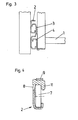
- FIG. 3 shows an end view the full extension guide, the adjacent parts of the drawer and the furniture body are also shown
- Fig. 4 shows a section along the line II of Fig. 1st
- the full extension set according to the invention has in a conventional manner on each side of the drawer 1 a body-side support rail 2, a middle rail 3 and a drawer-side pull-out rail 4.
- the drawer 1 is only indicated in FIG. 3 by the drawer side wall and the drawer bottom. Likewise, only part of the drawer side wall is drawn from the furniture body.
- the mounting rail has 2 stops 5, 6.
- the stops 5, 6 are also flexible material, such as rubber or plastic.
- the stops 5, 6 limit the extension path of the middle rail 3.
- the stop 5 forms the rear stop and the stop 6 the front stop for the roller 7, the middle rail 3.
- the mounting rail 2 has a punched-out opening 8 into which the stop 5 is suspended.
- the stop 5 overlaps the upper horizontal web 9 of the mounting rail 2.
- the stop 5 is approximately Z-shaped (see FIG. 4).
- the upper horizontal web 9 of the mounting rail 2 has a V-shaped bend 10 in a side view. Through this bend 10, the stop 5 is held immovably on the mounting rail 2.
- the stop 5 engages over the roller 7 on one end side with a lateral projection 11. This prevents the roller 7 from tipping about a lower axis of rotation, and likewise prevents the central rail 3 from moving sideways with the roller 7.
- the mounting rail 2 has a vertical web 12, which means a lateral guide for the roller 7.
- a recess 13 is located opposite the stop 5.
- the recess 13 is delimited at the front from the end of the vertical web 12 and at the rear by an angle 14 from the lower horizontal web 15 of the mounting rail 2, which forms the catwalk for the roller 7.
- each central rail 3 can be tilted away from the side wall of the body provided that it is fully pushed back into the supporting rails 1 and the roller 7 can thus be guided out through the recess 13.
- the stop 6 limits the running of the roller 7 at the front.
- the stop 6 has a rear stop part 15 and a front stop part 16. Normally, the roller 7 is only moved forward until it rests on the stop part 15. However, if the center rail 3 is to be fixed in the direction of displacement on the mounting rail 2, then the roller 7 is pulled further over the stop part 15, which is flexible, and then comes into the position shown in FIG. 2. Thus, the roller 7 and the middle rail 3 is held immovably on the mounting rail 2.
- stops 17 are also shown on the central rail 3. These stops 17 form a rear buffer for the roller (not shown) of the pull-out rail 4.
Landscapes
- Drawers Of Furniture (AREA)
- Compositions Of Oxide Ceramics (AREA)
- Auxiliary Devices For And Details Of Packaging Control (AREA)
- Insulating Bodies (AREA)
- Containers And Packaging Bodies Having A Special Means To Remove Contents (AREA)
- Fittings On The Vehicle Exterior For Carrying Loads, And Devices For Holding Or Mounting Articles (AREA)
- Impact Printers (AREA)
- Non-Reversible Transmitting Devices (AREA)
- Management, Administration, Business Operations System, And Electronic Commerce (AREA)
- Glass Compositions (AREA)
- Inorganic Insulating Materials (AREA)
- Semiconductor Lasers (AREA)
- Supports For Plants (AREA)
- Slide Fasteners (AREA)
- Laser Surgery Devices (AREA)
Applications Claiming Priority (2)
| Application Number | Priority Date | Filing Date | Title |
|---|---|---|---|
| AT3037/85 | 1985-10-21 | ||
| AT0303785A AT389988B (de) | 1985-10-21 | 1985-10-21 | Vollauszugsgarnitur fuer schubladen |
Publications (3)
| Publication Number | Publication Date |
|---|---|
| EP0219733A2 true EP0219733A2 (fr) | 1987-04-29 |
| EP0219733A3 EP0219733A3 (en) | 1988-06-15 |
| EP0219733B1 EP0219733B1 (fr) | 1990-12-05 |
Family
ID=3544308
Family Applications (1)
| Application Number | Title | Priority Date | Filing Date |
|---|---|---|---|
| EP86113519A Expired - Lifetime EP0219733B1 (fr) | 1985-10-21 | 1986-10-01 | Accessoire pour l'extraction complète de tiroirs |
Country Status (9)
| Country | Link |
|---|---|
| US (1) | US4728200A (fr) |
| EP (1) | EP0219733B1 (fr) |
| JP (1) | JPS6294110A (fr) |
| KR (1) | KR930003574Y1 (fr) |
| AT (2) | AT389988B (fr) |
| CA (1) | CA1278332C (fr) |
| DE (2) | DE8625606U1 (fr) |
| ES (2) | ES2018776B3 (fr) |
| IT (1) | IT211100Z2 (fr) |
Cited By (6)
| Publication number | Priority date | Publication date | Assignee | Title |
|---|---|---|---|---|
| DE3834721A1 (de) * | 1988-10-12 | 1990-04-19 | Schock Metallwerk | Auszugfuehrung mit selbsttaetig erreichbarer einschiebeendstellung |
| DE3923776A1 (de) * | 1989-07-06 | 1991-01-10 | Salice Arturo Spa | Ausziehfuehrung fuer schubkaesten oder dgl. |
| WO1992013473A1 (fr) * | 1991-02-12 | 1992-08-20 | Julius Blum Gesellschaft M.B.H. | Guide de sortie pour tiroirs |
| EP0820712B1 (fr) * | 1996-07-26 | 2001-05-30 | Julius Blum Gesellschaft m.b.H. | Dispositif de guidage de tiroir à glissière double |
| EP2500660A3 (fr) * | 2011-03-14 | 2014-05-14 | BSH Bosch und Siemens Hausgeräte GmbH | Dispositif de sortie |
| CN108686729A (zh) * | 2017-04-10 | 2018-10-23 | 豪夫迈·罗氏有限公司 | 用于实验室仪器的抽屉组件 |
Families Citing this family (13)
| Publication number | Priority date | Publication date | Assignee | Title |
|---|---|---|---|---|
| DE3822575A1 (de) * | 1987-07-02 | 1989-01-12 | Standard Praezision Gmbh | Behaeltnis mit zugglied und teleskopierbaren zuggliedfuehrungen |
| DE3818225C2 (de) * | 1988-05-28 | 1996-04-18 | Miele & Cie | Schubladenführung mit einer Rücklaufsperre |
| AT393781B (de) * | 1988-07-29 | 1991-12-10 | Blum Gmbh Julius | Ausziehfuehrungsgarnitur fuer schubladen od. dgl. |
| US5209572A (en) * | 1991-11-08 | 1993-05-11 | Accuride International, Inc. | Thin drawer slide |
| JP2580509Y2 (ja) * | 1992-09-30 | 1998-09-10 | 株式会社イトーキクレビオ | 拡張天板付き家具の天板案内装置 |
| DE19633241B4 (de) * | 1995-11-23 | 2005-07-28 | MEPLA-WERKE LAUTENSCHLäGER GMBH & CO. KG | Unterflur-Ausziehführung für Schubladen etc. |
| DE29622864U1 (de) * | 1995-11-23 | 1997-09-04 | Mepla-Werke Lautenschläger GmbH & Co KG, 64354 Reinheim | Unterflur-Ausziehführung für Schubladen etc. |
| US6027193A (en) * | 1999-02-26 | 2000-02-22 | Grass America, Inc. | Two-part undermount drawer guide assembly with pivot member |
| JP4571264B2 (ja) * | 2000-02-25 | 2010-10-27 | 京セラキンセキ株式会社 | 圧電振動子 |
| US6481812B1 (en) | 2000-09-19 | 2002-11-19 | Grass America, Inc. | Undermount drawer guide assembly |
| JP4154202B2 (ja) * | 2002-09-26 | 2008-09-24 | 日本スライド工業株式会社 | スライドレールのロック機構 |
| DE102004031724B4 (de) * | 2004-06-30 | 2018-10-31 | BSH Hausgeräte GmbH | Auszugssystem für Haushaltsgeräte |
| US20060192469A1 (en) * | 2005-02-25 | 2006-08-31 | Lg Electronics Inc. | Slide guide for pushing/drawing box into/out of refrigerator |
Family Cites Families (8)
| Publication number | Priority date | Publication date | Assignee | Title |
|---|---|---|---|---|
| CH341283A (de) * | 1956-01-25 | 1959-09-30 | Kuenzler Ernst | Doppelauszugeinrichtung für Schubladen und Auszugschieber |
| US3462203A (en) * | 1967-07-19 | 1969-08-19 | Grant Pulley & Hardware Corp | Safety stop for slide mechanism |
| BE708933A (fr) * | 1968-01-03 | 1968-05-16 | ||
| US3647271A (en) * | 1970-01-22 | 1972-03-07 | Allred Metal Stamping Works In | Drawer guide construction |
| DE2224226A1 (de) * | 1972-05-18 | 1973-11-29 | Nalasek & Edelkotte Ohg | Schubladenschrank |
| AT340631B (de) * | 1976-03-16 | 1977-12-27 | Fulterer & Co Kg | Schubladenfuhrung |
| AT386945B (de) * | 1982-02-17 | 1988-11-10 | Blum Gmbh Julius | Ausziehfuehrungsgarnitur fuer schubladen, insbesondere fuer plastikschubladen |
| DE3516957A1 (de) * | 1985-05-10 | 1986-11-13 | Alfred Grass GmbH Metallwarenfabrik, Höchst, Vorarlberg | Einfach- und voll-auszug fuer schubladen |
-
1985
- 1985-10-21 AT AT0303785A patent/AT389988B/de not_active IP Right Cessation
-
1986
- 1986-09-25 DE DE8625606U patent/DE8625606U1/de not_active Expired
- 1986-09-30 IT IT8606742U patent/IT211100Z2/it active
- 1986-10-01 DE DE8686113519T patent/DE3676040D1/de not_active Expired - Fee Related
- 1986-10-01 US US06/915,124 patent/US4728200A/en not_active Expired - Lifetime
- 1986-10-01 EP EP86113519A patent/EP0219733B1/fr not_active Expired - Lifetime
- 1986-10-01 ES ES86113519T patent/ES2018776B3/es not_active Expired - Lifetime
- 1986-10-01 AT AT86113519T patent/ATE58825T1/de not_active IP Right Cessation
- 1986-10-13 JP JP61241574A patent/JPS6294110A/ja active Granted
- 1986-10-16 KR KR2019860015850U patent/KR930003574Y1/ko not_active Expired - Fee Related
- 1986-10-16 CA CA000520678A patent/CA1278332C/fr not_active Expired - Fee Related
- 1986-10-17 ES ES19868600813U patent/ES1000470Y/es not_active Expired
Cited By (8)
| Publication number | Priority date | Publication date | Assignee | Title |
|---|---|---|---|---|
| DE3834721A1 (de) * | 1988-10-12 | 1990-04-19 | Schock Metallwerk | Auszugfuehrung mit selbsttaetig erreichbarer einschiebeendstellung |
| DE3923776A1 (de) * | 1989-07-06 | 1991-01-10 | Salice Arturo Spa | Ausziehfuehrung fuer schubkaesten oder dgl. |
| US5076712A (en) * | 1989-07-06 | 1991-12-31 | Arturo Salice S.P.A. | Track for guiding drawers |
| WO1992013473A1 (fr) * | 1991-02-12 | 1992-08-20 | Julius Blum Gesellschaft M.B.H. | Guide de sortie pour tiroirs |
| US5344227A (en) * | 1991-02-12 | 1994-09-06 | Julius Blum Gesellschaft M.B.H. | Extension guide assembly for a drawer |
| EP0820712B1 (fr) * | 1996-07-26 | 2001-05-30 | Julius Blum Gesellschaft m.b.H. | Dispositif de guidage de tiroir à glissière double |
| EP2500660A3 (fr) * | 2011-03-14 | 2014-05-14 | BSH Bosch und Siemens Hausgeräte GmbH | Dispositif de sortie |
| CN108686729A (zh) * | 2017-04-10 | 2018-10-23 | 豪夫迈·罗氏有限公司 | 用于实验室仪器的抽屉组件 |
Also Published As
| Publication number | Publication date |
|---|---|
| IT8606742V0 (it) | 1986-09-30 |
| JPH0254729B2 (fr) | 1990-11-22 |
| US4728200A (en) | 1988-03-01 |
| DE3676040D1 (de) | 1991-01-17 |
| IT211100Z2 (it) | 1989-02-13 |
| EP0219733A3 (en) | 1988-06-15 |
| ATA303785A (de) | 1989-08-15 |
| KR930003574Y1 (ko) | 1993-06-19 |
| JPS6294110A (ja) | 1987-04-30 |
| EP0219733B1 (fr) | 1990-12-05 |
| ATE58825T1 (de) | 1990-12-15 |
| AT389988B (de) | 1990-02-26 |
| KR870006291U (ko) | 1987-05-06 |
| DE8625606U1 (de) | 1987-03-05 |
| ES1000470U (es) | 1988-03-01 |
| CA1278332C (fr) | 1990-12-27 |
| ES1000470Y (es) | 1989-07-01 |
| ES2018776B3 (es) | 1991-05-16 |
Similar Documents
| Publication | Publication Date | Title |
|---|---|---|
| EP0219733B1 (fr) | Accessoire pour l'extraction complète de tiroirs | |
| AT401717B (de) | Schliessvorrichtung für schubladen | |
| AT407473B (de) | Vollauszug für schubladen | |
| AT401334B (de) | Schliessvorrichtung für schubladen | |
| EP0525153B1 (fr) | Guide de sortie pour tiroirs | |
| DE3035927C2 (de) | Führungsschienengarnitur, insbesondere für Schubladen | |
| DE3405802C2 (fr) | ||
| DE8610856U1 (de) | Vollauszugsgarnitur für Schubladen | |
| DE2846764A1 (de) | Ausziehfuehrung fuer schubladen o.dgl. | |
| DE29621957U1 (de) | Ausziehführung für Schublade | |
| AT1706U1 (de) | Ausziehführungsgarnitur für schubladen | |
| AT517479B1 (de) | Schubladenausziehführung | |
| EP0761133A1 (fr) | Ensemble de glissières pour tiroirs | |
| EP0613639B1 (fr) | Glissières pour tiroirs | |
| DE29619413U1 (de) | Ausziehführungsgarnitur für Schubladen | |
| EP0809956A2 (fr) | Dispositif à tiroirs pour un élément coulissant, encastrable dans une unité d'armoire | |
| EP0098511A1 (fr) | Ensemble de guidage pour le coulissement d'un tiroir ou autres | |
| AT399265B (de) | Ausziehführung für schubladen | |
| DE3010089A1 (de) | Ausziehfuehrung fuer schubladen o.dgl. | |
| DE2908391A1 (de) | Ausziehfuehrungsgarnitur fuer schubladen o.dgl. | |
| DE3019367A1 (de) | Aushaengbare auszugfuehrung | |
| DE3138204A1 (de) | Seitenverstellbare schiene einer schubladenfuehrungsgarnitur | |
| EP0218164B1 (fr) | Tiroir | |
| AT406109B (de) | Ausziehführungsgarnitur für schubladen | |
| AT400215B (de) | Ausziehführung für schubladen |
Legal Events
| Date | Code | Title | Description |
|---|---|---|---|
| PUAI | Public reference made under article 153(3) epc to a published international application that has entered the european phase |
Free format text: ORIGINAL CODE: 0009012 |
|
| AK | Designated contracting states |
Kind code of ref document: A2 Designated state(s): AT CH DE ES GB IT LI SE |
|
| PUAL | Search report despatched |
Free format text: ORIGINAL CODE: 0009013 |
|
| AK | Designated contracting states |
Kind code of ref document: A3 Designated state(s): AT CH DE ES GB IT LI SE |
|
| 17P | Request for examination filed |
Effective date: 19880513 |
|
| 17Q | First examination report despatched |
Effective date: 19890929 |
|
| GRAA | (expected) grant |
Free format text: ORIGINAL CODE: 0009210 |
|
| AK | Designated contracting states |
Kind code of ref document: B1 Designated state(s): AT CH DE ES GB IT LI SE |
|
| REF | Corresponds to: |
Ref document number: 58825 Country of ref document: AT Date of ref document: 19901215 Kind code of ref document: T |
|
| GBT | Gb: translation of ep patent filed (gb section 77(6)(a)/1977) | ||
| REF | Corresponds to: |
Ref document number: 3676040 Country of ref document: DE Date of ref document: 19910117 |
|
| ITF | It: translation for a ep patent filed | ||
| PLBE | No opposition filed within time limit |
Free format text: ORIGINAL CODE: 0009261 |
|
| STAA | Information on the status of an ep patent application or granted ep patent |
Free format text: STATUS: NO OPPOSITION FILED WITHIN TIME LIMIT |
|
| ITTA | It: last paid annual fee | ||
| 26N | No opposition filed | ||
| EAL | Se: european patent in force in sweden |
Ref document number: 86113519.2 |
|
| PGFP | Annual fee paid to national office [announced via postgrant information from national office to epo] |
Ref country code: CH Payment date: 20000914 Year of fee payment: 15 |
|
| PGFP | Annual fee paid to national office [announced via postgrant information from national office to epo] |
Ref country code: GB Payment date: 20001004 Year of fee payment: 15 |
|
| PGFP | Annual fee paid to national office [announced via postgrant information from national office to epo] |
Ref country code: ES Payment date: 20001013 Year of fee payment: 15 Ref country code: AT Payment date: 20001013 Year of fee payment: 15 |
|
| PGFP | Annual fee paid to national office [announced via postgrant information from national office to epo] |
Ref country code: SE Payment date: 20001017 Year of fee payment: 15 |
|
| PGFP | Annual fee paid to national office [announced via postgrant information from national office to epo] |
Ref country code: DE Payment date: 20001223 Year of fee payment: 15 |
|
| PG25 | Lapsed in a contracting state [announced via postgrant information from national office to epo] |
Ref country code: GB Free format text: LAPSE BECAUSE OF NON-PAYMENT OF DUE FEES Effective date: 20011001 Ref country code: AT Free format text: LAPSE BECAUSE OF NON-PAYMENT OF DUE FEES Effective date: 20011001 |
|
| PG25 | Lapsed in a contracting state [announced via postgrant information from national office to epo] |
Ref country code: SE Free format text: LAPSE BECAUSE OF NON-PAYMENT OF DUE FEES Effective date: 20011002 Ref country code: ES Free format text: LAPSE BECAUSE OF NON-PAYMENT OF DUE FEES Effective date: 20011002 |
|
| PG25 | Lapsed in a contracting state [announced via postgrant information from national office to epo] |
Ref country code: LI Free format text: LAPSE BECAUSE OF NON-PAYMENT OF DUE FEES Effective date: 20011031 Ref country code: CH Free format text: LAPSE BECAUSE OF NON-PAYMENT OF DUE FEES Effective date: 20011031 |
|
| REG | Reference to a national code |
Ref country code: GB Ref legal event code: IF02 |
|
| GBPC | Gb: european patent ceased through non-payment of renewal fee |
Effective date: 20011001 |
|
| EUG | Se: european patent has lapsed |
Ref document number: 86113519.2 |
|
| REG | Reference to a national code |
Ref country code: CH Ref legal event code: PL |
|
| PG25 | Lapsed in a contracting state [announced via postgrant information from national office to epo] |
Ref country code: DE Free format text: LAPSE BECAUSE OF NON-PAYMENT OF DUE FEES Effective date: 20020702 |
|
| REG | Reference to a national code |
Ref country code: ES Ref legal event code: FD2A Effective date: 20021113 |
|
| PG25 | Lapsed in a contracting state [announced via postgrant information from national office to epo] |
Ref country code: IT Free format text: LAPSE BECAUSE OF NON-PAYMENT OF DUE FEES Effective date: 20051001 |