EP0219800A2 - Dispositif de mélange de liquides - Google Patents
Dispositif de mélange de liquides Download PDFInfo
- Publication number
- EP0219800A2 EP0219800A2 EP86114192A EP86114192A EP0219800A2 EP 0219800 A2 EP0219800 A2 EP 0219800A2 EP 86114192 A EP86114192 A EP 86114192A EP 86114192 A EP86114192 A EP 86114192A EP 0219800 A2 EP0219800 A2 EP 0219800A2
- Authority
- EP
- European Patent Office
- Prior art keywords
- line
- liquid
- inlet
- pressure
- outlet
- Prior art date
- Legal status (The legal status is an assumption and is not a legal conclusion. Google has not performed a legal analysis and makes no representation as to the accuracy of the status listed.)
- Withdrawn
Links
Images


Classifications
-
- B—PERFORMING OPERATIONS; TRANSPORTING
- B01—PHYSICAL OR CHEMICAL PROCESSES OR APPARATUS IN GENERAL
- B01F—MIXING, e.g. DISSOLVING, EMULSIFYING OR DISPERSING
- B01F23/00—Mixing according to the phases to be mixed, e.g. dispersing or emulsifying
- B01F23/40—Mixing liquids with liquids; Emulsifying
- B01F23/49—Mixing systems, i.e. flow charts or diagrams
-
- B—PERFORMING OPERATIONS; TRANSPORTING
- B01—PHYSICAL OR CHEMICAL PROCESSES OR APPARATUS IN GENERAL
- B01F—MIXING, e.g. DISSOLVING, EMULSIFYING OR DISPERSING
- B01F35/00—Accessories for mixers; Auxiliary operations or auxiliary devices; Parts or details of general application
- B01F35/20—Measuring; Control or regulation
- B01F35/21—Measuring
- B01F35/211—Measuring of the operational parameters
- B01F35/2112—Level of material in a container or the position or shape of the upper surface of the material
-
- B—PERFORMING OPERATIONS; TRANSPORTING
- B01—PHYSICAL OR CHEMICAL PROCESSES OR APPARATUS IN GENERAL
- B01F—MIXING, e.g. DISSOLVING, EMULSIFYING OR DISPERSING
- B01F35/00—Accessories for mixers; Auxiliary operations or auxiliary devices; Parts or details of general application
- B01F35/20—Measuring; Control or regulation
- B01F35/22—Control or regulation
- B01F35/2201—Control or regulation characterised by the type of control technique used
- B01F35/2209—Controlling the mixing process as a whole, i.e. involving a complete monitoring and controlling of the mixing process during the whole mixing cycle
-
- B—PERFORMING OPERATIONS; TRANSPORTING
- B01—PHYSICAL OR CHEMICAL PROCESSES OR APPARATUS IN GENERAL
- B01F—MIXING, e.g. DISSOLVING, EMULSIFYING OR DISPERSING
- B01F25/00—Flow mixers; Mixers for falling materials, e.g. solid particles
- B01F25/30—Injector mixers
- B01F25/31—Injector mixers in conduits or tubes through which the main component flows
- B01F25/312—Injector mixers in conduits or tubes through which the main component flows with Venturi elements; Details thereof
Definitions
- the invention relates to a device for mixing liquids according to the preamble of claim 1.
- a device for mixing water and a disinfectant concentrate is known.
- the water is removed from the water network via a line and flows via an electrical low water protection device, a removal valve and an electrically operated solenoid valve as well as a pipe aerator with a flow regulator to an injector metering head, which is designed as a water jet pump, which draws in disinfectant concentrate from a canister via a suction line and mixed with the flowing water.
- a sensor monitors the conductivity and temperature of the disinfectant solution produced. The determined values are compared with setpoints in a control unit. If there is a deviation from the setpoint, the solenoid valve is activated, which blocks the water supply to the water jet pump, which simultaneously stops the supply of the solvent concentrate.
- the disadvantage is that the dosage depends directly on the water pressure. Since a sufficiently precise dosage can only be achieved at constant water pressure, the known device works imprecisely in the event of pressure fluctuations. There is a risk that the measured conductivity value deviates too much from the setpoint value, which results in a forced shutdown of the device via the solenoid valve and an error message.
- Another disadvantage is that the separation between the water network and disinfectant concentrate or disinfectant solution is not guaranteed, since the valves used do not offer sufficient security against a backflow of disinfectant solution and thus against contamination of the tap water.
- the object of the present invention is to design a device according to the preamble of claim 1 so that the metering accuracy is maintained even with pressure fluctuations of the liquid under pressure and a backflow is prevented with certainty.
- a uniform liquid pressure is set for the injector regardless of the pressure of the liquid supplied, as a result of which a uniform dosage can be achieved for each adjustable mixing ratio of the liquids.
- the air gap provided makes it possible to achieve an absolute separation between the liquids to be mixed and, in particular, between the liquid fed to the injector under pressure and the liquid mixture, thereby reliably avoiding contamination of the liquid fed under pressure.
- the drawing shows a device 1 for mixing liquids.
- the device 1 has an inlet line 2, via which liquid under pressure, for example water, can be supplied from the water network.
- the inlet line 2 leads to a pressure expansion tank 3, in the exemplary embodiment according to the drawing specifically into an outlet line 4 of the pressure expansion tank 3.
- the outlet line 4 connects the outlet 5 of the pressure expansion tank 3 to an inlet 6 of an injector 7.
- a pressure reducer 8 and a solenoid valve 9 are located in the inlet line 2.
- a pressure switch 10 is connected to the outlet line 4 of the pressure compensating container 3.
- the end of the outlet line 4 is designed as a nozzle 11, in front of which a jet regulator 12 is arranged in the outlet line.
- the injector 7 is designed in the manner of a water jet pump.
- a further nozzle 13 is connected to the inlet 6 of the injector 7 or the inlet 6 is designed as a nozzle 13.
- the nozzles 11 and 13 are not firmly connected to one another, but there is an air gap 14 of approximately 20 mm between the two.
- the injector 7 has a suction nozzle 15, to which a suction line is connected, which is connected to a suction lance 17, which projects into a storage tank 18, the second one, which is under pressure Contains liquid to be mixed, for example a disinfectant concentrate.
- a backflow preventer 19 and a nozzle 20 are arranged in the suction line 16.
- An outlet line 22, in which a jet regulator 23 is arranged, is connected to the outlet 21 of the injector 7.
- a sensor 24 for level monitoring is connected to the nozzle 13.
- the sensor 24 is intended to prevent the nozzle 13 from overflowing.
- a sensor 25 which carries out a conductivity measurement.
- a measuring probe for level control is connected to the suction lance.
- the output signals of the pressure switch 10, the level monitoring sensor 24, the flow control sensor 25 and the fill level measuring probe 26 are fed to a control device 27 for processing and outputting control signals.
- the device works as follows: The pressurized liquid flowing in via the feed line 2 flows into the pressure compensation container 3 after passing through the pressure reducer 8 and the solenoid valve 9.
- the pressure compensation container When the pressure compensation container is filled, the air column 28 in the pressure compensation container is compressed until a certain liquid pressure is reached, which is achieved by the pressure switch 10 is scanned, the output signal of which is evaluated in the control device 27, which controls when the presettable pressure of the solenoid valve is reached to close. In this way, a specific liquid pressure of the liquid to be fed to the injector 7 can be adjusted, which fluctuates slightly around an average value.
- the liquid emerging from the surge tank leaves the nozzle 11 well bundled as a liquid jet and then flows after flowing through the air gap 14 into the nozzle 13 of the inlet 6 of the injector 7.
- a constant negative pressure is generated in the injector by the liquid jet leaving the nozzle 13. through which the liquid to be mixed is sucked in from the reservoir 18 via the suction line 16. This liquid is mixed in the injector 7 with the liquid from the surge tank and the mixture flows out of the outlet line 22.
- the amount of liquid drawn from the reservoir 18 is determined by the setting of the nozzle 20 in the suction line and by the pressure held constant in the surge tank, which means that the mixing ratio is determined by the nozzle 20 and the pressure in the surge tank.
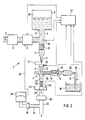
- FIG. 2 shows a modified embodiment which basically works exactly like the device according to FIG. 1.
- the device shown in FIG. 2 differs from that according to FIG. 1 in that measures are still taken on the consumer side in order to close the device to make a pressure device, for example for connecting bedpans (for example in hospitals), foot showers, spray lances, spray hoses and the like.
- a check valve 33 is arranged in the outlet line 22, to which is connected on the outlet side a line 32 which can be connected to a consumer and which is connected via a branch line 34 to a pressure expansion tank 38.
- a pressure switch 36 by means of which the inlet line 2 can be blocked as a function of the outlet pressure, which can be done by appropriately controlling the solenoid valve 9 via a line 40, as shown in FIG. 2.
- the pressure accumulator 38 is pressurized with compressed air.
- the pressure switch 36 closes the solenoid valve 9 at a presettable outlet pressure (for example 2 bar), so that a further inflow into the outlet line is blocked until the outlet pressure again falls below the threshold value (here for example 2 bar). Blocking the inlet line via the solenoid valve 9 creates a pressure difference in the lines 22 and 32, as a result of which the check valve 30 closes. If the outlet pressure then falls below the threshold value, the pressure difference also disappears. The solenoid valve releases the feed line again and the check valve opens again.
- a presettable outlet pressure for example 2 bar
- a collecting container 44 is provided, the amount of liquid of which can be scanned with the aid of a liquid level sensor 46.
- This scanner 46 is preferably connected to the control device 27, as shown, for signaling a maximum liquid level.
- FIG. 3 shows a simplified embodiment of the device according to FIGS. 1 or 2.
- the inlet line 2 is connected directly to the inlet connection 6 of the injector 7.
- a tube aerator 48 is arranged in the inlet line 2 or the outlet line 4.
- a liquid level sensor 10 ' can also be provided, which directly senses the liquid level in the pressure equalization container 3 and whose measurement signal is fed to the control device 27 for evaluation, as shown in broken lines in FIG. 1.
Landscapes
- Chemical & Material Sciences (AREA)
- Chemical Kinetics & Catalysis (AREA)
- Nozzles (AREA)
- Accessories For Mixers (AREA)
Applications Claiming Priority (2)
| Application Number | Priority Date | Filing Date | Title |
|---|---|---|---|
| DE3536992 | 1985-10-17 | ||
| DE3536992A DE3536992C1 (de) | 1985-10-17 | 1985-10-17 | Vorrichtung zum Mischen von Fluessigkeiten |
Publications (2)
| Publication Number | Publication Date |
|---|---|
| EP0219800A2 true EP0219800A2 (fr) | 1987-04-29 |
| EP0219800A3 EP0219800A3 (fr) | 1988-03-09 |
Family
ID=6283796
Family Applications (1)
| Application Number | Title | Priority Date | Filing Date |
|---|---|---|---|
| EP86114192A Withdrawn EP0219800A3 (fr) | 1985-10-17 | 1986-10-14 | Dispositif de mélange de liquides |
Country Status (3)
| Country | Link |
|---|---|
| EP (1) | EP0219800A3 (fr) |
| JP (1) | JPS6415124A (fr) |
| DE (1) | DE3536992C1 (fr) |
Cited By (3)
| Publication number | Priority date | Publication date | Assignee | Title |
|---|---|---|---|---|
| EP0443963A1 (fr) * | 1990-02-23 | 1991-08-28 | Hospal Industrie | Détecteur d'écoulement d'un premier liquide dans un circuit de circulation d'un second liquide |
| EP0465336A1 (fr) * | 1990-07-03 | 1992-01-08 | Claude-Jean Desvigne | Appareil doseur de produits liquides pour engins agricoles |
| US20140169121A1 (en) * | 2011-07-20 | 2014-06-19 | Seko, S.P.A. | Mixing apparatus assembly with air gap separation, in particular for backflow prevention |
Families Citing this family (2)
| Publication number | Priority date | Publication date | Assignee | Title |
|---|---|---|---|---|
| DE102016001626B4 (de) | 2015-02-13 | 2022-02-17 | Schulz Gmbh | Verfahren zur Bereitstellung eines Desinfektions- oder Reinigungskonzentrats |
| GB201704760D0 (en) * | 2017-01-05 | 2017-05-10 | Illumina Inc | Reagent nozzle sipper mixing system and method |
Family Cites Families (7)
| Publication number | Priority date | Publication date | Assignee | Title |
|---|---|---|---|---|
| US206427A (en) * | 1878-07-30 | Improvement in printersj chases | ||
| DE307544C (fr) * | ||||
| US3094135A (en) * | 1959-03-10 | 1963-06-18 | Hydraulique & Urbanisme | Arrangement for feeding a reagent in amounts proportional to the output of water to be treated by said reagent |
| US3376886A (en) * | 1966-06-03 | 1968-04-09 | Chemagnetics Controls Corp | Universal chemical feeder |
| US4094786A (en) * | 1977-10-11 | 1978-06-13 | Bury John R | Treatment control apparatus for water systems |
| DE3339420A1 (de) * | 1983-10-29 | 1985-05-09 | Weber und Springmann GmbH, 3200 Hildesheim | Vorrichtung zum dosierbaren zugeben eines stoffes zu einem loesungs- oder verduennungsmittel |
| DE3400263A1 (de) * | 1984-01-05 | 1985-07-18 | Göldner - Vieregge-Bruns Hygienetechnik GmbH, 3070 Nienburg | Einrichtung zur ueberwachung der anwendungskonzentration von desinfektionsmittelloesungen |
-
1985
- 1985-10-17 DE DE3536992A patent/DE3536992C1/de not_active Expired
-
1986
- 1986-10-14 EP EP86114192A patent/EP0219800A3/fr not_active Withdrawn
- 1986-10-17 JP JP61245625A patent/JPS6415124A/ja active Pending
Cited By (5)
| Publication number | Priority date | Publication date | Assignee | Title |
|---|---|---|---|---|
| EP0443963A1 (fr) * | 1990-02-23 | 1991-08-28 | Hospal Industrie | Détecteur d'écoulement d'un premier liquide dans un circuit de circulation d'un second liquide |
| EP0465336A1 (fr) * | 1990-07-03 | 1992-01-08 | Claude-Jean Desvigne | Appareil doseur de produits liquides pour engins agricoles |
| FR2664179A1 (fr) * | 1990-07-03 | 1992-01-10 | Desvigne Claude Jean | Appareil doseur de produits liquides pour engins agricoles. |
| US20140169121A1 (en) * | 2011-07-20 | 2014-06-19 | Seko, S.P.A. | Mixing apparatus assembly with air gap separation, in particular for backflow prevention |
| US9375688B2 (en) * | 2011-07-20 | 2016-06-28 | Seko S.P.A. | Mixing apparatus assembly with air gap separation, in particular for backflow prevention |
Also Published As
| Publication number | Publication date |
|---|---|
| DE3536992C1 (de) | 1987-02-19 |
| EP0219800A3 (fr) | 1988-03-09 |
| JPS6415124A (en) | 1989-01-19 |
Similar Documents
| Publication | Publication Date | Title |
|---|---|---|
| DE2720210C3 (de) | Vorrichtung zum Eichen eines Meßfühlers in einer Blutprobenmefieinrichtung | |
| DE69826804T2 (de) | Flüssigkeitsverteilvorrichtung und Verfahren | |
| DE3911028C2 (de) | Verfahren und Vorrichtung zum Zumessen von Waschmittel in eine Waschlösung | |
| DE2330445A1 (de) | Trennanlage | |
| DE3400263C2 (fr) | ||
| DE3339420C2 (fr) | ||
| DE1646030A1 (de) | Pulverzufuehrungsvorrichtung fuer eine Flammspritzpistole | |
| EP0219800A2 (fr) | Dispositif de mélange de liquides | |
| DE68917590T2 (de) | Herstellung einer mischung aus flüssigkeiten. | |
| EP0432673A2 (fr) | Dispositif mobile pour produire des mélanges actifs sur base de l'eau | |
| DE1947549A1 (de) | Melksystem | |
| EP0155683B1 (fr) | Procédé et dispositif de préparation de liquides pour arroser d'engrais les plantes à l'usage de ménages et des jardiniers amateurs | |
| DE2738531C2 (de) | Vorrichtung zum Eindosieren einer Zusatzflüssigkeit in eine Hauptflüssigkeit | |
| DE2944186A1 (de) | Vorrichtung zum einfuehren von fluessigkeiten in einen menschlichen oder tierischen koerper | |
| DE602004001491T2 (de) | Belüftungssystem mit einem Umkehrosmose-Filtereinsatz | |
| CH639566A5 (de) | Dosiergeraet zur dosierung einer gaszugabe in fluessigkeiten. | |
| DE102009017126B4 (de) | Verfahren zur Wasseraufbereitung sowie Einrichtung hierfür | |
| DE102005002448B4 (de) | Vorrichtung und Verfahren zum Messen, Steuern oder Prüfen | |
| DE2556245C2 (de) | Zumischvorrichtung für ein Schaumlöschgerät | |
| EP1517213B1 (fr) | Appareil de dosage pour la production à partir de concentrés d'une solution de produit désinfectant prête à l'emploi | |
| DD260429A1 (de) | Vorrichtung zum kontinuierlichen herstellen von standardisierter milch | |
| EP0048342B1 (fr) | Procédé et dispositif pour fournir un fluide sous pression qui est pompé sous une pression variable | |
| EP0583545B1 (fr) | Dispositif de mesure en continu de la concentration de saumure | |
| DE2612119A1 (de) | Fluessigkeitsabgabe- und dampfauffangvorrichtung | |
| EP0226969A2 (fr) | Dispositif pour la fabrication d'un mélange réactif d'au moins deux composants de matériau synthétique |
Legal Events
| Date | Code | Title | Description |
|---|---|---|---|
| PUAI | Public reference made under article 153(3) epc to a published international application that has entered the european phase |
Free format text: ORIGINAL CODE: 0009012 |
|
| AK | Designated contracting states |
Kind code of ref document: A2 Designated state(s): AT BE CH DE FR GB IT LI LU NL SE |
|
| PUAL | Search report despatched |
Free format text: ORIGINAL CODE: 0009013 |
|
| AK | Designated contracting states |
Kind code of ref document: A3 Designated state(s): AT BE CH DE FR GB IT LI LU NL SE |
|
| STAA | Information on the status of an ep patent application or granted ep patent |
Free format text: STATUS: THE APPLICATION IS DEEMED TO BE WITHDRAWN |
|
| 18D | Application deemed to be withdrawn |
Effective date: 19880912 |