EP0219963B1 - Herstellung von Strumpfhosen - Google Patents
Herstellung von Strumpfhosen Download PDFInfo
- Publication number
- EP0219963B1 EP0219963B1 EP86306933A EP86306933A EP0219963B1 EP 0219963 B1 EP0219963 B1 EP 0219963B1 EP 86306933 A EP86306933 A EP 86306933A EP 86306933 A EP86306933 A EP 86306933A EP 0219963 B1 EP0219963 B1 EP 0219963B1
- Authority
- EP
- European Patent Office
- Prior art keywords
- garment
- machine
- gusset
- transfer
- pantihose
- Prior art date
- Legal status (The legal status is an assumption and is not a legal conclusion. Google has not performed a legal analysis and makes no representation as to the accuracy of the status listed.)
- Expired
Links
- 238000004519 manufacturing process Methods 0.000 title claims description 25
- 238000012546 transfer Methods 0.000 claims description 78
- 230000007246 mechanism Effects 0.000 claims description 48
- 238000003780 insertion Methods 0.000 claims description 27
- 230000037431 insertion Effects 0.000 claims description 27
- 238000000034 method Methods 0.000 claims description 20
- 238000004826 seaming Methods 0.000 claims description 19
- 238000012545 processing Methods 0.000 claims description 13
- 230000000977 initiatory effect Effects 0.000 claims 3
- 239000000969 carrier Substances 0.000 description 7
- 238000006073 displacement reaction Methods 0.000 description 4
- 238000009940 knitting Methods 0.000 description 4
- 238000009958 sewing Methods 0.000 description 4
- 239000004744 fabric Substances 0.000 description 3
- 238000000926 separation method Methods 0.000 description 3
- 238000011144 upstream manufacturing Methods 0.000 description 2
- 208000031872 Body Remains Diseases 0.000 description 1
- 230000006978 adaptation Effects 0.000 description 1
- 238000013461 design Methods 0.000 description 1
- 238000011161 development Methods 0.000 description 1
- 230000018109 developmental process Effects 0.000 description 1
- 230000000694 effects Effects 0.000 description 1
- 238000012986 modification Methods 0.000 description 1
- 230000004048 modification Effects 0.000 description 1
- 238000004806 packaging method and process Methods 0.000 description 1
- 238000004321 preservation Methods 0.000 description 1
- 230000000717 retained effect Effects 0.000 description 1
Images


Classifications
-
- D—TEXTILES; PAPER
- D05—SEWING; EMBROIDERING; TUFTING
- D05B—SEWING
- D05B23/00—Sewing apparatus or machines not otherwise provided for
- D05B23/007—Sewing units for assembling parts of knitted panties or closing the stocking toe part
-
- D—TEXTILES; PAPER
- D05—SEWING; EMBROIDERING; TUFTING
- D05D—INDEXING SCHEME ASSOCIATED WITH SUBCLASSES D05B AND D05C, RELATING TO SEWING, EMBROIDERING AND TUFTING
- D05D2303/00—Applied objects or articles
- D05D2303/20—Small textile objects e.g., labels, beltloops
Definitions
- the present invention relates to the manufacture of pantihose, and more particularly to gussetted pantihose.
- the traditional gussetted pantihose manufacturing routine involves a plurality of separate operations.
- Third, a gore piece or cusset is inserted and seamed into the crutch of the garment e.g. using a gussetting machine.
- Fourth, the free ends of the tubes (that form the legs) are closed by a toe closing seam.
- Fifth, the garment is usually boarded before packaging. At a convenient stage in the manufacturing process, the garment is dyed.
- a common factor in existing transfer-automated hosiery machine systems has been the line closer. That is, the line closer has been linked either to a toe closer or to a gusset-inserting machine.
- Hosiery knitting machines are now being developed which produce a one-piece knitted pantihose garment. Such a garment is formed on the knitting machine with open-ended tubular legs linked together at the top to form the body of the garment, and the need for line closing is obviated.
- Present-day transfer-automated machine systems founded on line closers would be useless for the manufacturer equipped to produce the one-piece knitted garment.
- the resulting system is well suited for use with the above-mentioned one-piece knitted pantihose garment, although the system may include a line closer linked as an input to the gusset-inserting machine.
- a method wherein the garment is mounted on a support body and a first manufacturing operation is performed on the thus-supported garment, the garment is transferred from said body to a pair of supports over which its legs are drawn and a second manufacturing operation is performed on the thus-supported garment, the body being placed in a given orientation on the pair of supports, thanks to a preliminary orienting manipulation of the garment before transfer commences.
- a pantihose garment the method involving the steps of mounting the garment on a gusset inserting machine, inserting a gusset, and transferring the garment from said machine to another machine having a pair of supports over which the garment and its legs are drawn, the garment being placed in a given orientation demanded by the said other machine on the latter, for example it is rotated lengthwise to place a medial plane thereof (e.g, a body seam) in a predetermined attitude to obtain the given orientation, while it is on the gusset inserting machine and preferably after the gusset insertion step.
- a medial plane thereof e.g, a body seam
- the method can involve the steps of mounting the garment on a gusset inserting machine, inserting a gusset, and transferring the garment from said machine to another machine having a pair of supports over which the garment and its legs are drawn, and the garment is rotated lengthwise to place a medial plane thereof (e.g. a body seam) in a predetermined attitude after the gusset insertion step, so as to place it in a given orientation demanded by said other machine, the garment being rotated by a suitably controlled rotation of a support body of the gusset machine on which the garment is mounted for gusset insertion.
- a medial plane thereof e.g. a body seam
- pantihose manufacturing apparatus comprising a first machine having a support body to mount a pantihose garment while the first machine performs a first processing operation on the garment, a second machine having a pair of supports over which the garment and its legs are to be drawn prior to the second machine performing its processing operation on the garment, and means to strip the garment from the support body and to transfer it onto said pair of supports in a given orientation demanded by the second machine, the apparatus preferably including means to dispose the garment on the said support body in a given attitude related to said orientation before the stripping means operates to strip and transfer, the stripping means being operative in a manner such that the attitude of the garment is undisturbed.
- the invention also provides pantihose manufacturing apparatus comprising a gusset inserting machine having a head for supporting the body of a pantihose garment while a gusset is inserted into a crutch area of the body, another machine for performing a hosiery manufacturing operation on the garment being operatively associated with the gusset inserting machine and having a pair of supports for receiving the garment and its legs after insertion of a gusset, and transfer means for stripping the garment from the gusset machine and for mounting it on the said pair of supports in a given orientation demanded by the said other machine, the gusset machine for example including means to rotate the garment about its lengthwise direction preferably after gusset insertion to place a medial plane thereof (e.g. a body seam) in a predetermined attitude so as to set the garment body to the given orientation.
- a medial plane thereof e.g. a body seam
- a gusset inserting machine has a support head for a pantihose garment, the head being rotatably mounted, and means is provided to rotate the head through an angle predetermined to dispose the garment in a predetermined attitude immediately prior to the garment being stripped from the head for transfer to a receiving machine.
- the apparatus shown by way of example in the drawings is for use in manufacturing gussetted pantihose starting from open-ended tubular leg blanks.
- the processes performed by the apparatus involve several seaming operations. In sequence, the operations are line closing, gusset insertion and toe closing.
- the invention is not limited to apparatus comprising in particular, a line closer, a gusset inserter and a toe closer.
- line closer 10 Full details of the line closer 10 are omitted from this specification since line closers are well known in the art. Several types exist. One such line closer is made by Takatori Machinery Works Ltd. of Yamatotakeda City, Japan under several Model numbers, e.g. LC-240, LC-280 and LC-320. See, for example, US-A-4 303 026. Another well known line closer is the Savio Model TC developed by Savio & C S.P.A. of Milan, Italy. For the sake of illustration, the line closer 10 is a Savio Model TC machine.
- the line closer 10 has a plurality of supports 11, for tubular hose blanks.
- the supports extend forwardly from a turret 12 which turns about a central, horizontally-disposed turning axis.
- the supports extend parallel to the axis and move around an endless path, and during their movement they visit a loading station, a seaming station (neither illustrated for clarity), and an unloading station shown in Fig. 1.
- a seaming machine S/M such as a sewing machine, to form the pantihose body.
- the body seam S of the pantihose garment P is generated in a predetermined plane. Relative to the finished garment, this seam plane extends parallel to and equidistantly spaced between the garment legs when they are stretched out from the body in their usual side-by-side positions. The seam thus extends centrally from the garment waistband at the front, down through the crutch and centrally up to the garment waistband at the back.
- the garment P is moved still on its two supports 11 to the unloading station.
- the said plane of seam S is central between the two supports, extends parallel to their lengths and is normal to a plane containing both supports.
- the plane is in a vertical attitude at the unloading station.
- a transfer mechanism t 1 is operative to strip the garment P from the line closer supports 11 and to load it on an unoccupied head 20 of a gusset inserting machine C.
- Mechanism t 1 will be discussed later with reference to Fig. 4.
- Gusset inserting machines are known in the art and several kinds exist.
- the gusset machine illustrated is that manufactured and marketed by Detexomat Machinery Limited under the trade mark AUTOGUSSET. Further details are to be found in GB-B-2 001 238 and GB-B-2 058 856 and US-A-4 220 104. The gusset machine G will now be described briefly.
- the machine G has a horizontal turntable 21 which rotates intermittently about its central vertical axis 22, so as to move each of the heads 20 around an endless path. During their movement, the heads 20 pass in sequence through a series of work stations 24 to 28.
- the turntable rotates counterclockwise as indicated by the arrow in Fig. 1.
- the heads 20 are spaced equally apart around the periphery of the turntable 21 and each projects radially therefrom.
- the heads are cylindrical bodies and each is mounted to rotate about its radially-disposed central axis.
- a head 20 receives a pantihose garment P from line closer L via transfer mechanism t l .
- the body of the garment is placed on the head such that the seam S remains in a vertical plane.
- the seam extends axially along the top and bottom of the head, vertically and diametrically across the outer end of the head.
- Only the body of the garment P is mounted on the head: the legs are sucked into a suction holding duct 30 (Fig. 4) and retained therein from the time the garment is placed on the gusset machine G until it is discharged therefrom.
- the garment body is firmly held in position on head 20 by a pair of inwardly- movable clamps 32.
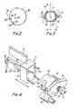
- a hole cutter 35 is brought into engagement with the crutch area of the body, said crutch area being held tautly across the end of the head 20 by means of the clamps 32.
- the cutter 35 could be e.g. a hot wire or a sharp circular blade.
- a hole is formed in the crutch area ready for receiving a gusset.
- a gusset piece 40 is cut from a web of gusset fabric and presented to the end of head 20 by gusset holding means (not shown). Inside the end of the head is a ring of movable pins 41 (Fig. 3). The pins are axially movable from recessed to projecting positions relative to the end of the head, to project therefrom for the gusset piece to be impaled on them. Once a gusset piece 40 has been impaled on the pins 41, the latter are manipulated to cause each to incline forwardly and outwardly relative to the end of the head and its centre. So inclined, the pins 41 prevent the gusset piece 40 from being inadvertently displaced from the pins.
- the clamps 32 are then shifted forwardly a predetermined distance. This movement advances the edge of the hole in the crutch area towards and beyond the end of the head 20.
- the respective fabrics around the edges of the hole and the gusset piece are thereby brought into juxtaposition for seaming together, e.g. by overlock sewing.
- the juxtaposed fabrics are presented to a seamer 50, for instance an overlock sewing machine.
- the head 20 is now rotated about its central, radially-disposed axis. Thanks to the clamps 32 and the pins 41 the body and gusset piece 40 are rendered fast for rotation with the head 20.
- the seamer 50 generates the required seam joining the gusset piece to the body as the head rotates.
- the heads 20 are each fast with a shaft 51 (see Fig. 4) projecting rearwardly therefrom into a bearing, not shown, mounted on the turntable 21.
- a wheel 52 and pinion 53 are affixed to the shaft 51 and to this, also, is keyed a bracket 54 on which the clamps 32 are mounted.
- the suction holding duct 30 for the garment legs is mounted to rotate in unison with the associated head 20, to prevent twisting of the legs relative to the body.
- the wheel 52 is brought into engagement with a drive wheel (not shown) rotated by an electric motor controlled to cause the head 20 to rotate at a speed and for a period of time appropriate to generate the required seam and the required number of stitches per unit length.
- the garment P now having the gusset piece 40 seamed in place is discharged from the gusset machine G and transferred to the toe closer T with the aid of a rotary conveyor C.
- the gusset machine G is shown in Fig. 1 as having eight heads. There may be more or fewer.
- the AUTOGUSSET machine in fact has five heads which move in turn between the five stations illustrated.
- the line closer L established the seam S in a predetermined plane relative to the legs of the garment. Further, at the discharge position of the line closer L, the seam plane was in a vertical attitude. The garment was transferred to and mounted on the head of the gusset machine G with the seam plane preserved in this vertical attitude.
- the toe closer T is called upon to generate toe closing seams extending across the ends of the garment legs and located in a predetermined orientation relative to the body seam S.
- the precise orientation depends on the type of toe seam. With fish-mouth seams, for instance, their orientation is to be in a plane normal to the body seam.
- the garment P first has to be mounted properly on a pair of toe closer supports 60, such that the body seam S is central between the supports 60.
- the plane of seam S should extend lengthwise parallel to the supports.
- the seam S should lie in a plane normal to the plane containing the supports 60. (This, indeed, was the way in which the seam S was related to the supports 11 of the line closer.)
- repositioning of the garment is accomplished in this example at station 28 on the gusset machine G.
- the head 20 is responsible for effecting the required reorientation, and means provided to transfer the garment P to the toe closer T is designed to preserve the attitude of the reoriented garment.
- the wheel 51 is disengaged from the drive therefor and the head assumes a position such that the body seam S lies in a substantially vertical plane 61, see Fig. 3.
- the clamps 32 and their mounting bracket 54 are disposed generally horizontally, which disposition applied when the clamps first engaged the garment P upon its initial mounting on the head 20.
- a rack 62 see Fig. 5, is caused to engage the pinion 53 on the shaft 51 secured to the head 20.
- the rack is displaced, e.g.
- a ram a specified distance adequate to rotate the pinion 53 (and hence the shaft 51, clamp bracket 54, clamps 32 and head 20) through a reorientation angle (a) appropriate for positioning the seam plane to accord with the requirements for the toe closer.
- the attitude of the reoriented seam plane is indicated in Fig. 3 at 63, and the garment legs are appropriately oriented each for transfer onto the allotted toe closer support 60', 60".
- a transfer mechanism t 2 to be described removes the body from head 20 and mounts it on conveyor C.
- mechanism t 2 pulls the body over a pair of adjacent supports, e.g. in the form of tubes 70, projecting from rotary conveyor means 71 towards the head 20.
- the conveyor means 71 is a circular carousel 72 which rotates about its centre on a turning axis 73 inclined to the horizontal.
- the carousel 72 has several (four as shown) pairs of tubes 70 projecting from its rim and spaced equally thereabout.
- the tubes of each pair are mutually parallel.
- the pairs of tubes are aligned relative to two mutually perpendicular diameters of the carousel.
- a plane containing each pair of tubes 70 bears a definite angular relationship to the turning axis 73, and in this example all the tubes 70 lie in a common plane parallel to the plane of the carousel and normal to said axis 73.
- the conveyor 70 rotates intermittently in the direction arrowed in Fig. 1, to move the tubes 70 having a garment P loaded thereon by mechanism t 2 to a position adjacent the toe closer supports 60 to receive the garment.
- another transfer mechanism t 3 serves to transfer the garment to the supports 60 from the conveyor 70. This mechanism t 3 will be described later.
- the inclination of the carousel 72, and the arrangement of the tubes 70 thereon, are such that as each pair of tubes moves into position adjacent the two receiving toe closer supports 60, planes through these tubes and the two supports are parallel. See Fig. 2 where x-x represents the position of the tubes 70.
- Reorientation of the garment body by head 20 disposes to body seam S centrally relative to the two tubes 70 about to receive the garment p.
- the seam plane is normal to a plane containing these two tubes.
- the thus- oriented body is mounted on the tubes 70 in this orientation which is preserved as the tubes 70 move around into conjunction with the two receiving toe closer supports 60, so that the body will be presented thereto in this, the required orientation.
- the transfer mechanism t 2 draws the garment only partially onto the receiving tubes 70.
- a two wheel wind-on device 76 temporarily engages the body on the tubes 70.
- the device 76 winds the garment wholly onto the tubes, each leg being drawn fully over a respective tube.
- Two air jets from nozzles 77 then blow the garment legs towards the ends of the respective tubes 70 and suction is created in each.
- the garment body remains around the two tubes 70 and the legs extend along them and into their interiors.
- the leg portions inside the tubes are everted relative to the leg portions outside, and upon, the tubes.
- the supports 70 do not have to be tubes to which suction is applied. It is feasible for the garment P to be mounted on a support of the carousel 72 such that the legs, or the lower parts thereof, dangle freely from the support. Supported in this way, transfer mechanism t 3 is capable of transferring the garment P from the carousel to the toe closer T and of loading the garment P properly on the toe closer.
- the toe closer T can be of any known type, such as that manufactured and marketed by Detexomat Machinery Limited under the trade mark SPEEDOMATIC HS. See, for example, GB-B-1 501 869; GB-B-1 577 758; US-A-4192 242; GB-B-2 074 203 and US-A-4 383 490. Since it is well known in the art full details will not be given here.
- the toe closer has a turret 80 rotatable intermittently about its central horizontal axis 81, in the direction indicated in Fig. 2.
- the supports 60 project from the turret 80.
- the toe closer indexes the supports around an endless path of travel and as they move, they pass through several work stations.
- the following operations may be performed.
- the garment legs may be wound fully onto the supports 60.
- the legs may be positioned automatically longitudinally and/or rotationally so that they are in a predetermined position and attitude permitting toe seams to be formed correctly thereacross.
- the toe ends of the garment legs are presented to a movable clamping device which conveys them in turn past a seamer S/M at the next station.
- the toe ends are presented to and moved past the seamer S/M.
- Seams are generated across the toe end of each leg, e.g. by an overlock sewing machine. Following the seaming station is a discharge station.
- the garment may be everted and conveyed, e.g. pneumatically, to a collection bin or to another hosiery processing machine in the manufacturing plant.
- the garment P In the course of its passage through the apparatus, the garment P is everted or turned inside-out and vice versa several times. Assuming the garment is right side out on the line closer, its body is turned inside out when being mounted on the gusset machine head 20. The body is turned right side out when mounted on the rotary conveyor C, while its legs are turned inside-out into the conveyor tubes 70 in readiness for the subsequent mounting on the toe closer supports 60. The body and legs are disposed inside out upon the supports 60.
- the garment is mounted on the support of conveyor C such that its legs dangle freely, see foregoing description, they will be everted inside out when drawn onto the toe closer supports 60 following mounting of the body thereon inside out.
- Transfer mechanism t is located and movable between the line closer supports 11.
- the mechanism has movable clamps or fingers which engage or grip the waistband of the garment P. See Fig. 4. Upper and lower reaches of the waistband encircling the line closer supports 11 are engaged by the clamps or fingers, which are manipulatable to open the waistband appropriately to pass it over the gusset machine head 20.
- the mechanism t utilises fingers 90 pivotally mounted in a support body 91. Inside the body is camming means or the like for controlling the pivotal movement of the fingers 90 to ensure they open the waisband suitably.
- the body 91 is mounted on the ends of elongate arms 92 slidably mounted in bearings (not shown) for movement parallel to the aligned supports 11 and gusset head 20.
- Drive means 93 such as a pneumatic ram, camming mechanism or a ball screw device (similar to a machine lead screw- device) has a drive connection 94 to the arms 92 for reciprocating them, the body 91 and fingers jointly through an operating cycle of the mechanism t l .
- the operating cycle commences with the body 91 and fingers 90 in a starting position rearwardly of the waistband.
- the body and fingers are moved forwards (towards the gusset machine) to engage the fingers 90 with the waistband.
- the body 91 and fingers are pivoted to open the waistband and move it, plus the adjoining body portion, over the gusset head 20.
- the legs are sucked into duct 30.
- the forward movement of the fingers 90 terminates when they have moved the waistband to and beyond the location of the clamps 32 associated with the head 20.
- Drive means 93 then returns the body 91 and fingers 90 rearwardly to the starting position and the clamps 32 are then activated.
- the clamps move (i) inwardly to grip the garment body to the head 20 and (2) rearwardly relative to the head 20. The latter movement draws the crutch area taut across the end of the head.
- the mechanism t 1 is designed to transfer the body from the line closer L to gusset machine G without disturbing the vertical attitude of the body seam S.
- Preservation of the seam attitude may not be wholly essential, but it simplifies overall management of the operation of the apparatus.
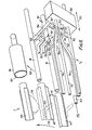
- Fig. 5 shows the transfer mechanism t 2 operable between the gusset machine G and the rotary conveyor C.
- Mechanism t 2 operates when head 20 has swung along horizontal path 99 into station 28 and two unoccupied tubes 70 of the conveyor 71 are aligned with the head 20, as indicated by the chain dotted line.
- the mechanism has a carriage 100 reciprocally movable between the head 20 and the tubes 70, suitable drive means 101 being coupled to move the carriage in the directions indicated by arrow 102.
- the drive means 101 can be any of the types suggested above for the transfer mechanism t i .
- the carriage can be secured to movable arms 104 coupled to drive means 101.
- the carriage 100 can be movable to and fro along fixed guide arms 104, when the drive means 101 is coupled to the carriage.
- Adjacent wire frames are mounted on the carriage 100.
- frame components 106, 107 move with the carriage from the illustrated position into the mouth of the head 20.
- Frame components 106, 107 clamp the garment crutch area against an internal, diametrically-oriented face located just inside the mouth, against movement inadvertently from its reoriented attitude when the contact with the body.
- the apparatus is now ready for the garment body to be stripped from the head 20 and deposited on the transfer mechanism t 2 . Stripping is accomplished by air jets from nozzles 110 and by retraction of the pins 41. The air jets blow the garment body from around the head to around the confronting wire frame components 106, 107, the body being everted in the process.
- the pins 41 are disengaged from the gusset piece when the body has been transferred onto the wire frame components.
- a mechanical stripping means can be employed instead of air jets.
- Such stripping means can comprise fingers mounted to enter the waistband of the body mounted on the head 20 and to move the waistband forwards to place it and the garment body on the wire frame components. As before, the pins 41 are then retracted.
- the said wire frames include respective frame components 112 and 114 flanking wire frame components 106.
- Frame components 106,112 and 114 are mounted on associated vertical rods 116 pivoted to turn about their respective central axes 117 on link arms 118.
- Wire frame components 112, 114 project outwardly to "catch" or arrest the waistband as the garment is blown from the head 20 or is otherwise conveyed across to the wire frames.
- Means, not shown, are provided for pivoting the rods 116 so as to swing the wire components 112,114 and also wire components 106 outwardly, in opposite directions. Arrows 120, 121 indicate these pivoting movements of the rods 116 and the said frame components.
- the rods 116 are pivoted in opposite directions to cause their associated frame elements 106 to move apart, non-slippably to grip the garment waistband and stretch it.
- the garment legs remain stored inside the suction duct 30.
- both rods 116 and frame components 106 are moved apart from one another, further stretching the waistband.
- the frame components 106 are thus moved further apart, until they are spaced by a distance governed by, and which is not less than, the overall width across the two conveyor tubes 70. This opens the waistband sufficiently for it to be drawn about the two tubes 70.
- the carriage 100 then executes a transfer stroke by operation of drive means 101, the carriage and frame components 106 moving generally along the tubes to don the garment body thereon.
- suction may be relieved from the duct 30 to let the legs move outwards therefrom.
- the frame components 106 slip from the waistband, leaving the body stretched around the tubes 70.
- the carriage 100 can then be returned by drive means 101 to a position in readiness for transferring another garment. The return movement is along a path permitting the next pair of tubes to enter station 28 without fouling the carriage.
- the conveyor 71 indexes in the direction of arrow 130.
- the garment legs now leave the duct 30, and wind-on device 76 is now activated as described above.
- the body Before transfer from gusset machine G to conveyor C, therefore, the body is reoriented to suit the inclined attitude of the two receiving conveyor tubes 70.
- This attitude which is matched to the inclination of the toe closer supports 60 ultimately to receive the garment, is preserved during operation of transfer mechanism t 2 . Thanks to the reorientation, the seam is disposed properly for the conveyor C and toe closer T and the garment is so disposed that its legs will transfer smoothly onto the tubes 70 without any significant twist developing between the body and legs.
- Fig. 6 shows the transfer mechanism t 3 operable between the rotary conveyor C and the toe closer T.
- tubes 70 bearing a garment are generally aligned with toe closer supports 60', 60".
- the tubes 70 and supports 60 could be in exact alignment, i.e. coplanar and colinear.
- transfer mechanism t 3 can be a simple design adaptation of transfer mechanism t l . It may not be convenient to have the tubes 70 and supports 60 so exactly aligned, however.
- Mechanism t 3 is designed for the situation illustrated where the tubes 70 are closer together than the supports 60 and are in a different but parallel plane. The mutual positioning of tubes 70 and supports 60 is best appreciated from Fig. 2.
- Mechanism t 3 has a carriage 150 movable, parallel alongside the tubes 70 and supports 60, in transfer or forward and return or rearward strokes. Its direction of travel is shown by arrow 151. Rails 152 guide the carriage in its travel. A push-pull rod 153 couples the carriage 150 to drive means comprising a pneumatic actuator 154 or some other drive means as suggested hereinbefore.
- Two arms 156 project from the carriage 150 part-way towards the tubes 70. Pivotally mounted between the arms, one to each arm, are two L-shaped fingers or brackets 157.
- the fingers 157 are movable between retracted positions (shown dotted for one of them) and garment-engaging positions shown in solid lines. Pneumatic actuators, camming means or the like, not shown, may be employed to pivot the fingers in unison between their said positions.
- the forwardly cranked ends of the fingers 157 project between the tubes 70 to enter the top, waistband end of the garment.
- the fingers 157 may be moved to the garment-engaging positions before or shortly after the carriage 150 commences its transfer stroke, which is leftwards as seen in Fig. 6.
- the fingers have to be positioned rearwardly beyond the waistband when they are moved to the garment-engaging positions.
- the arms 156 are retractably mounted to the carriage 150.
- the fingers 157 are retractable along the arms towards the carriage.
- Pneumatic actuators, camming means or the like are activated for retraction after the fingers 157 have engaged the garment. Howsoever accomplished, the fingers are retracted from between the tubes 70 by a distance which is determined by the need for the fingers to draw the garment onto the toe closer supports 60, and hence is governed by the amount by which they are offset relative to tubes 70. See Fig. 2.
- the fingers are retracted (arrows 160) while the carriage is moving leftwards.
- the supports 60 are spaced further apart from one another than the tubes 70. This necessitates a movement of the fingers 157 away from one another, until they are separated by a distance permitting them to travel freely along the supports 60.
- the fingers have to move in the direction of arrows 161. This movement is produced by displacing the arms 156 consequential upon the leftward travel of the carriage 150.
- the arms 156 are thus mounted to the carriage 150 for movement in the direction of arrows 161, and have followers 162 which ride on associated cam tracks 164.
- the two cam tracks 164 provide identical rises 166 in this instance.
- the cam rises are located to the right of the free ends of the supports 60 since the fingers must have attained the necessary separation by the time they reach the supports 60. The retraction and separation of the fingers are maintained as the carriage moves them leftwardly along the supports 60.
- the latter Due to the close positioning of the tubes 70 and supports 60, and to the combined retraction and separation of the fingers 157, the latter are able to slip the garment body smoothly from the tubes 70 and onto the supports 60.
- the body only is transferred to the supports 60: the legs remain inside the tubes 70.
- the body is everted as it is mounted on the supports 60 and the legs are already in an inside-out state inside their respective tubes 70.
- the fingers are pivoted backwards (arrows 158) to slip them from the garment waistband.
- the carriage then executes its rightwards return stroke in the course of which the fingers 157 are restored to their starting positions in readiness for transferring the next garment to the toe closer T.
- the toe closer turret 80 indexes in the direction of arrow 170.
- the garment legs are pulled partly from the tubes 70.
- Supports 60' and 60" move to the positions of support 60a and support 60'.
- Support 60' is now located adjacent the mouth 172 of a suction tube 174 aligned therewith.
- Suction in tube 174 draws the leg to be mounted on support 60' wholly from tube 70 and into this tube.
- a wind-on device 176 is then engaged with the garment portion on support 60' and activated to draw the hose leg out of suction tube 174 and fully onto support 60. Thanks to suction in tube 174, the leg is de- twisted for proper mounting on support 60'. The operation is repeated when the turret 80 next indexes bringing support 60' opposite suction tube 174.
- the garment is mounted on the supports in an everted state, eversion being accomplished in two stages.
- the first stage everts the legs only, when the tubes 70 of conveyor 71 are in the intermediate position between their garment-receiving and garment- delivering positions.
- the second stage everts the body in the course of its mounting on the supports 60.
- the invention can be embodied in ways differing from what is described and illustrated. For example, if one starts with one-piece knitted garments, the line closer L will be omitted. The gusset machine G will then be loaded with said garments manually or automatically, and gusset insertion and toe closing will proceed as described.
- a boarding machine could be substituted, such machine having one or more pairs of supports onto which the garment is to be drawn.
- a toe closer could be placed upstream of the gusset machine G in that case, the toe-closed garment being for instance automatically loaded on the machine G by a transfer device constructed along the lines of mechanism t j .
- Hosiery processing apparatus could then comprise the following machines linked in sequence: line closer, toe closer, gusset machine and boarding machine. The line and toe closers could be transposed. Mechanisms similar to transfer mechanism t, link the two closers together and link the second closer to the gusset machine. Linking of the gusset machine to the boarding machine is by means of mechanism t 2 /t 3 already described.
- a boarding machine of turret type could take the place of the rotary conveyor C, when only transfer mechanism t 2 would be needed.
- reorientation of the garment involved a substantial angular rotational displacement of the head 20.
- the displacement is of the order of 45° - 60°, for instance 54°.
- Such a large displacement would not always be necessary, depending on the toe closer or other machine downstream of the gusset machine G.
- the twin forms of the downstream machine might lie in a horizontal plane at their loading position. It might then be thought there would be no call for reorienting the garment body.
- the gusset head is rotated through rather more than 360° or 180° during gusset seaming so there is a need for controllably rotating the head 20 after seaming to set the body seam accurately to an attitude suiting the downstream machine.
- references to the body seam plane and its attitude or orientation should be understood to refer to an equivalent medial plane through a one-piece garment if the invention is practised on such a garment.
- the equipment effects a rotation of the garment for aligning it appropriately with the two supports of the receiving machine, the latter supports being inclined appreciably to the horizontal.
- the need to rotate the garment could be avoided if the said supports were themselves in a different orientation, e.g. if the plane containing them were horizontal or vertical or otherwise if they were at an orientation matching the machinery upstream of the gusset machine.
- the garment will then be transferred from the gusset machine to the receiving machine in a manner whereby the garment is preserved in the orientation required by the receiving machine.
- the illustrated line closer L has a turret rotating on a horizontal axis.
- the body seam is in a vertical plane.
- Line closers that have a carousel rotating about a vertical axis could also be used, e.g. any of the aforesaid Takatori machines.
- the body seam is then generated in a horizontal plane and the pantihose garment is stripped from such a line closer with the body seam horizontal.
- the toe closer T disclosed above has a hose loading station wherein the two leg tubes or supports 60 to receive a pantihose garment lie in a common plane that is neither horizontal nor vertical.
- the toe closer could be adapted so that the plane of the leg tubes is e.g. horizontal at the loading position.
- the leg tubes will be thus when at "bottom dead centre”.
- Such horizontally-disposed leg tubes will be well suited for operation with the illustrated line closer since the body seam will be in the vertical plane when stripped from the line closer and this is the attitude required then for loading the toe closer.
- the toe closer could be adapted so that the leg tubes 60 lie in a vertical plane at the loading station.
- Vertically-disposed leg tubes are well suited for operation with Takatori line closers, because when they are loaded the body seam will be in a horizontal plane, and this is the attitude of the seam at the unloading or stripping position of the line closer.
- the gusset machine can be arranged whereby its head rotation is such that upon completion of the gusset seam, the pantihose garment has its body seam already in an attitude e.g. vertical or horizontal, matching the needs of the toe closer loading station.
- a deliberate, post-gussetting rotation of the gusset machine head to position the seam in the plane required by the toe closer can be eliminated. For example, suppose the gusset machine head 20 receives the garment P with the seam S horizontal, and the twin-support, receiving machine has its supports disposed for receiving the garment P with the seam in this attitude.
- the head Before gusset seaming, the head could be given a predetermined rotation in one rotational sense, and upon seaming is rotated in the opposite sense through this predetermined rotation plus 360°, ensuring a complete gusset seam is formed and returning the body seam S to the horizontal upon completion of the gusset seam.
- the garment body is manipulated before transfer for placement in a given orientation on the twin supports of the receiving machine e.g. the toe closer and while it is still mounted on the preceding operation machine e.g. the gusset machine.
- the appropriate manipulation of the garment can be performed before or after the preceding operation machine has performed its designated task.
- the manipulation is conveniently performed by rotating the single support body on which the garment is mounted.
- the manipulation could be accomplished in other ways e.g. by rotating the garment on and relative to the said support body for instance by a rotary displacement of the clamps 32.
- the toe closer can be adapted such that its loading station is oriented to receive the pantihose garment with its body seam in the same attitude as it had at the line closer unloading station, and the gusset machine can be adapted to preserve this attitude at completion of the gussetting operation.
- the operation of the gusset machine can be beneficially simplified.
- Hosiery processing apparatus can comprise a plurality of hosiery processing machines each to perform a designated operation on pantihose articles, the machines being linked by automatic transfer mechanism such that said articles are transferred from one machine to the next and are mounted thereby on the latter.
- the apparatus according to the invention can comprise, for example, the following linked machines arranged in the following order:
Landscapes
- Engineering & Computer Science (AREA)
- Textile Engineering (AREA)
- Sewing Machines And Sewing (AREA)
- Treatment Of Fiber Materials (AREA)
Claims (30)
Applications Claiming Priority (4)
| Application Number | Priority Date | Filing Date | Title |
|---|---|---|---|
| GB858522438A GB8522438D0 (en) | 1985-09-10 | 1985-09-10 | Pantihose |
| GB8522438 | 1985-09-10 | ||
| GB8529364 | 1985-11-28 | ||
| GB858529364A GB8529364D0 (en) | 1985-09-10 | 1985-11-28 | Pantihose manufacture |
Publications (2)
| Publication Number | Publication Date |
|---|---|
| EP0219963A1 EP0219963A1 (de) | 1987-04-29 |
| EP0219963B1 true EP0219963B1 (de) | 1989-05-10 |
Family
ID=26289751
Family Applications (1)
| Application Number | Title | Priority Date | Filing Date |
|---|---|---|---|
| EP86306933A Expired EP0219963B1 (de) | 1985-09-10 | 1986-09-09 | Herstellung von Strumpfhosen |
Country Status (3)
| Country | Link |
|---|---|
| US (2) | US4784070A (de) |
| EP (1) | EP0219963B1 (de) |
| DE (1) | DE3663272D1 (de) |
Families Citing this family (23)
| Publication number | Priority date | Publication date | Assignee | Title |
|---|---|---|---|---|
| IT1213838B (it) * | 1987-10-16 | 1990-01-05 | Solis Srl | Dispositivo per il trasferimento automatico dei collant da unamacchina per cucire i collant ad un trasportatore dei collant a pacchi |
| GB8807547D0 (en) * | 1988-03-30 | 1988-05-05 | Flude & Hinckley | Automatic flat seaming apparatus |
| GB8910318D0 (en) * | 1989-05-05 | 1989-06-21 | Flude & Hinckley | Apparatus for loading a line closing machine |
| US5207166A (en) * | 1989-11-23 | 1993-05-04 | Detexomat Machinery Limited | Method and apparatus for making pantyhose with a comfort gusset |
| JPH03173597A (ja) * | 1989-11-30 | 1991-07-26 | Takatori Haitetsuku:Kk | 股上縫製機におけるパンティストッキング生地の自動位置決装置 |
| GB2240993B (en) * | 1990-02-15 | 1993-12-15 | Detexomat Machinery Ltd | Improvements relating to the handling of hosiery |
| US5165355A (en) * | 1991-03-26 | 1992-11-24 | Sara Lee Corporation | Method and apparatus for handling hosiery blanks |
| US5277139A (en) * | 1991-07-01 | 1994-01-11 | Honeycutt Larry W | Sewing apparatus |
| DE4225008C1 (de) * | 1991-08-14 | 1993-03-18 | Moll, Philipp, 5100 Aachen, De | |
| IT1252801B (it) * | 1991-09-23 | 1995-06-28 | Solis Srl | Metodo di cucitura automatica di due calze per la formazione di un collant e macchina per attuare il detto metodo |
| US5255621A (en) * | 1992-06-24 | 1993-10-26 | Westpoint Pepperell Inc. | Turret pocket setter for tubular fabrics |
| US5363785A (en) * | 1992-08-24 | 1994-11-15 | Mim Industries, Inc. | Non-intrusive workpiece pallet locator |
| IT1262476B (it) * | 1993-04-01 | 1996-06-28 | Solis Srl | Metodo e macchina per la cucitura automatica di due calze da donna performare un collant. |
| GB9402684D0 (en) * | 1994-02-11 | 1994-04-06 | Detexomat Machinery Ltd | A hosiery line closer and loader assembly |
| GB9507510D0 (en) * | 1995-04-11 | 1995-05-31 | Detexomat Machinery Ltd | Method & apparatus for manipulating a length of flexible material |
| US5699942A (en) * | 1995-07-21 | 1997-12-23 | Sara Lee Corporation | Automatic sleeve invertor |
| IT1286591B1 (it) * | 1996-04-04 | 1998-07-15 | Solis Srl | Metodo e dispositivo per il trattamento di manufatti tubolari tessuti a maglia,specialmente calze |
| US5651483A (en) * | 1996-05-24 | 1997-07-29 | Monarch Knitting Machinery Corporation | Apparatus and method of delivering hosiery blanks or pantyhose in proper orientation for further processing |
| US6334547B1 (en) | 1997-07-19 | 2002-01-01 | Detexomat Machinery Limited | Method and apparatus for manipulating a length of flexible material |
| ITFI20060249A1 (it) * | 2006-10-13 | 2008-04-14 | Golden Lady Co Spa | Dispositivo per allineare il bordo circondante una estremita' di un manufatto a maglia tubolare e relativo metodo |
| ITFI20120126A1 (it) * | 2012-06-21 | 2013-12-22 | Bicchierai S R L | Macchina per l'applicazione di tasselli perineali ai collant. |
| CN109385763B (zh) * | 2017-08-07 | 2021-07-02 | 杰克缝纫机股份有限公司 | 一种用于裁片旋转送料的移料装置 |
| EP3686333A1 (de) * | 2019-01-23 | 2020-07-29 | Jeanología, S.L. | Hose-laserbehandlungseinrichtung und entsprechender hose-halter |
Family Cites Families (23)
| Publication number | Priority date | Publication date | Assignee | Title |
|---|---|---|---|---|
| US2905366A (en) * | 1956-12-12 | 1959-09-22 | Floyd R Shoaf | Apparatus for feeding hosiery onto a receiving member |
| US3520262A (en) * | 1967-08-23 | 1970-07-14 | Chadbourn Gotham Inc | Method and apparatus for closing stocking toes and putting stockings on boarding forms for processing |
| FR2211951A5 (en) * | 1972-12-21 | 1974-07-19 | Heliot Maurice Ets | Handling device with rotatable platform for panty hose - automatically removes them from formers and deposits them on a rail |
| GB1575756A (en) * | 1976-02-20 | 1980-09-24 | Mabi Srl | Machine for sewing the toes of stockings |
| US4188898A (en) * | 1977-09-06 | 1980-02-19 | Takatori Machinery Mfg. Co., Ltd. | System for combining stocking materials and gussets to form panty hose garments |
| IT7809326A0 (it) * | 1978-01-27 | 1978-01-27 | Chietti Giovanni | Apparecchiatura semiautomatica per il caricamento di manufatti tubolari per calze o simili su macchine cucitrici e per altri impieghi |
| IT1069950B (it) * | 1979-01-09 | 1985-03-25 | Solis Srl | Metodo per applicare un tassello a manufatti tubolari come calzemutande da signora e macchina per attuare detto metodo |
| GB2066862B (en) * | 1980-01-07 | 1983-10-05 | Detexomat Machinery Ltd | Method and apparatus for seaming toes in hosiery manufacture |
| JPS5731891A (en) * | 1980-07-31 | 1982-02-20 | Sukeo Mori | Inserting fitting device for stocking cloth in end automatic sewing machine for seamless stocking |
| EP0057055B1 (de) * | 1981-01-23 | 1985-04-17 | Detexomat Machinery Limited | Einrichtung und Verfahren zur Behandlung von Strümpfen |
| US4364320A (en) * | 1981-02-23 | 1982-12-21 | Consolidated Foods Corporation | Garment toe closing system |
| GB2094616B (en) * | 1981-03-18 | 1985-04-17 | Flude H & Co Hinckley Ltd | Spade gusset seaming apparatus |
| IT1167930B (it) * | 1981-06-26 | 1987-05-20 | Solis Srl | Macchina per l'ispezione e la striatura con fissaggio di manufatti a calzamutanda e simili |
| US4487546A (en) * | 1981-08-05 | 1984-12-11 | Savio & C. S.P.A. | Device for transferring tubular fabrics from support hangers to a rigid body and inverting the fabric |
| JPS5835255A (ja) * | 1981-08-27 | 1983-03-01 | Toyota Motor Corp | デイ−ゼルエンジンの排気ガス再循環装置 |
| US4444140A (en) * | 1981-12-14 | 1984-04-24 | Monarch Knitting Machinery Corporation | Method of making panty hose and apparatus to make same |
| IT1151814B (it) * | 1982-06-28 | 1986-12-24 | Savio & C Spa | Dispositivo per trasferire collants e simili da una macchina per la loro cucitura ad un dispositivo di prelevamento |
| IT1198509B (it) * | 1983-01-21 | 1988-12-21 | Solis Srl | Perfezionamenti relativi ad un procedimento e ad una macchina,per trasferire automaticamente o collants da una macchina che produce collants con cuciture ad una macchina per cucire tasselli |
| GB8303159D0 (en) * | 1983-02-04 | 1983-03-09 | Detexomat Machinery Ltd | Transferring hosiery between manufacturing machines |
| JPS59168882A (ja) * | 1983-03-15 | 1984-09-22 | 株式会社 タカトリ機械製作所 | パンテイストツキングの股上縫製機とつま先縫製機の連結受渡し方法及び装置 |
| EP0126800B1 (de) * | 1983-05-31 | 1988-01-20 | Takatori Machinery Works Ltd. | Maschine und Verfahren um Strumpfhose automatisch und anhaltend zu schliessen |
| IT1198683B (it) * | 1983-09-19 | 1988-12-21 | Solis Srl | Dispositivo per il caricamento rapido dei collant su macchina di finitura delle calze,specialmente provvista di rovesciatore pneumatico |
| EP0136391B1 (de) * | 1983-09-22 | 1987-04-22 | SOLIS S.r.l. | Nähen von Strumpfhosen auf einer Transfermaschine die aus mehreren, einander folgenden Karussels besteht |
-
1986
- 1986-09-03 US US06/903,257 patent/US4784070A/en not_active Expired - Fee Related
- 1986-09-09 DE DE8686306933T patent/DE3663272D1/de not_active Expired
- 1986-09-09 EP EP86306933A patent/EP0219963B1/de not_active Expired
-
1988
- 1988-09-02 US US07/240,834 patent/US4862815A/en not_active Expired - Fee Related
Also Published As
| Publication number | Publication date |
|---|---|
| EP0219963A1 (de) | 1987-04-29 |
| DE3663272D1 (en) | 1989-06-15 |
| US4784070A (en) | 1988-11-15 |
| US4862815A (en) | 1989-09-05 |
Similar Documents
| Publication | Publication Date | Title |
|---|---|---|
| EP0219963B1 (de) | Herstellung von Strumpfhosen | |
| US4550868A (en) | Method and apparatus for transferring hosiery between hosiery manufacturing machines | |
| US4539924A (en) | Loading system for a toe closing assembly | |
| CA2045796C (en) | Material handling system | |
| JPH0243517B2 (de) | ||
| US4364320A (en) | Garment toe closing system | |
| US4598817A (en) | Loading system for a toe closing assembly | |
| USRE32481E (en) | Boarding apparatus | |
| US4602710A (en) | Loading system for a toe closing assembly | |
| JP2000511855A (ja) | 更なる処理のために適切な配向で靴下ブランク又はパンティーストッキングを供給する装置及び方法 | |
| US5511501A (en) | Method and apparatus for handling flexible objects | |
| US6913173B2 (en) | Method and apparatus for opening, positioning and loading socks on forms | |
| US5406900A (en) | Method and apparatus for attaching sleeves to tubular shirt bodies | |
| US4440329A (en) | Apparatus for unloading hosiery machinery | |
| WO1995027097A1 (en) | Method and apparatus for handling flexible objects | |
| US4321881A (en) | Method and apparatus for inserting a gusset in panti-hose | |
| US3434438A (en) | Apparatus for automatically closing the ends of tubular fabric articles | |
| CN113574220B (zh) | 裤子处理装置及相应的裤架 | |
| GB2058856A (en) | Seaming gussets to garments | |
| GB2027331A (en) | Machine for manufacturing pantie-hose with a gusset | |
| EP0153796A1 (de) | Vorrichtung und Verfahren um eine kurvenförmige Naht zu erhalten | |
| US5609118A (en) | Hosiery line closer and loader assembly | |
| GB2240993A (en) | Improvements relating to the handling of hosiery | |
| WO1993000467A1 (en) | Automatic spade gusset seaming apparatus | |
| JPS6028514B2 (ja) | 環状生地の縫製方法並びに装置 |
Legal Events
| Date | Code | Title | Description |
|---|---|---|---|
| PUAI | Public reference made under article 153(3) epc to a published international application that has entered the european phase |
Free format text: ORIGINAL CODE: 0009012 |
|
| AK | Designated contracting states |
Kind code of ref document: A1 Designated state(s): DE FR GB IT |
|
| 17P | Request for examination filed |
Effective date: 19870527 |
|
| 17Q | First examination report despatched |
Effective date: 19880722 |
|
| GRAA | (expected) grant |
Free format text: ORIGINAL CODE: 0009210 |
|
| AK | Designated contracting states |
Kind code of ref document: B1 Designated state(s): DE FR GB IT |
|
| ITF | It: translation for a ep patent filed | ||
| REF | Corresponds to: |
Ref document number: 3663272 Country of ref document: DE Date of ref document: 19890615 |
|
| ET | Fr: translation filed | ||
| PLBE | No opposition filed within time limit |
Free format text: ORIGINAL CODE: 0009261 |
|
| STAA | Information on the status of an ep patent application or granted ep patent |
Free format text: STATUS: NO OPPOSITION FILED WITHIN TIME LIMIT |
|
| 26N | No opposition filed | ||
| ITTA | It: last paid annual fee | ||
| PGFP | Annual fee paid to national office [announced via postgrant information from national office to epo] |
Ref country code: FR Payment date: 19940819 Year of fee payment: 9 |
|
| PGFP | Annual fee paid to national office [announced via postgrant information from national office to epo] |
Ref country code: DE Payment date: 19940825 Year of fee payment: 9 |
|
| PGFP | Annual fee paid to national office [announced via postgrant information from national office to epo] |
Ref country code: GB Payment date: 19950907 Year of fee payment: 10 |
|
| PG25 | Lapsed in a contracting state [announced via postgrant information from national office to epo] |
Ref country code: FR Effective date: 19960531 |
|
| PG25 | Lapsed in a contracting state [announced via postgrant information from national office to epo] |
Ref country code: DE Effective date: 19960601 |
|
| REG | Reference to a national code |
Ref country code: FR Ref legal event code: ST |
|
| PG25 | Lapsed in a contracting state [announced via postgrant information from national office to epo] |
Ref country code: GB Effective date: 19960909 |
|
| GBPC | Gb: european patent ceased through non-payment of renewal fee |
Effective date: 19960909 |
|
| PG25 | Lapsed in a contracting state [announced via postgrant information from national office to epo] |
Ref country code: IT Free format text: LAPSE BECAUSE OF NON-PAYMENT OF DUE FEES;WARNING: LAPSES OF ITALIAN PATENTS WITH EFFECTIVE DATE BEFORE 2007 MAY HAVE OCCURRED AT ANY TIME BEFORE 2007. THE CORRECT EFFECTIVE DATE MAY BE DIFFERENT FROM THE ONE RECORDED. Effective date: 20050909 |