EP0220060A2 - Grilles de support pour un assemblage de combustible - Google Patents
Grilles de support pour un assemblage de combustible Download PDFInfo
- Publication number
- EP0220060A2 EP0220060A2 EP86308007A EP86308007A EP0220060A2 EP 0220060 A2 EP0220060 A2 EP 0220060A2 EP 86308007 A EP86308007 A EP 86308007A EP 86308007 A EP86308007 A EP 86308007A EP 0220060 A2 EP0220060 A2 EP 0220060A2
- Authority
- EP
- European Patent Office
- Prior art keywords
- grid
- straps
- cell
- fuel
- factor
- Prior art date
- Legal status (The legal status is an assumption and is not a legal conclusion. Google has not performed a legal analysis and makes no representation as to the accuracy of the status listed.)
- Granted
Links
Images


Classifications
-
- G—PHYSICS
- G21—NUCLEAR PHYSICS; NUCLEAR ENGINEERING
- G21C—NUCLEAR REACTORS
- G21C3/00—Reactor fuel elements and their assemblies; Selection of substances for use as reactor fuel elements
- G21C3/30—Assemblies of a number of fuel elements in the form of a rigid unit
-
- G—PHYSICS
- G21—NUCLEAR PHYSICS; NUCLEAR ENGINEERING
- G21C—NUCLEAR REACTORS
- G21C3/00—Reactor fuel elements and their assemblies; Selection of substances for use as reactor fuel elements
- G21C3/30—Assemblies of a number of fuel elements in the form of a rigid unit
- G21C3/32—Bundles of parallel pin-, rod-, or tube-shaped fuel elements
- G21C3/34—Spacer grids
- G21C3/3424—Fabrication of spacer grids
-
- Y—GENERAL TAGGING OF NEW TECHNOLOGICAL DEVELOPMENTS; GENERAL TAGGING OF CROSS-SECTIONAL TECHNOLOGIES SPANNING OVER SEVERAL SECTIONS OF THE IPC; TECHNICAL SUBJECTS COVERED BY FORMER USPC CROSS-REFERENCE ART COLLECTIONS [XRACs] AND DIGESTS
- Y02—TECHNOLOGIES OR APPLICATIONS FOR MITIGATION OR ADAPTATION AGAINST CLIMATE CHANGE
- Y02E—REDUCTION OF GREENHOUSE GAS [GHG] EMISSIONS, RELATED TO ENERGY GENERATION, TRANSMISSION OR DISTRIBUTION
- Y02E30/00—Energy generation of nuclear origin
- Y02E30/30—Nuclear fission reactors
-
- Y—GENERAL TAGGING OF NEW TECHNOLOGICAL DEVELOPMENTS; GENERAL TAGGING OF CROSS-SECTIONAL TECHNOLOGIES SPANNING OVER SEVERAL SECTIONS OF THE IPC; TECHNICAL SUBJECTS COVERED BY FORMER USPC CROSS-REFERENCE ART COLLECTIONS [XRACs] AND DIGESTS
- Y10—TECHNICAL SUBJECTS COVERED BY FORMER USPC
- Y10S—TECHNICAL SUBJECTS COVERED BY FORMER USPC CROSS-REFERENCE ART COLLECTIONS [XRACs] AND DIGESTS
- Y10S376/00—Induced nuclear reactions: processes, systems, and elements
- Y10S376/90—Particular material or material shapes for fission reactors
Definitions
- This invention relates to fuel assembly support grids for nuclear reactors and, more particularly, is concerned with support grids made from zirconium alloy metal material having a predetermined grain orientation which reacts to irradiation so as to offset the effects of irradiation-induced stress relaxation of the grid components which hold the fuel rods of the assembly.
- the reactor core is comprised of a large number of elongated fuel assemblies.
- Conventional designs of these fuel assemblies include a plurality of fuel rods held in an organized array by a plurality of grids spaced axially along the fuel assembly length and attached to a plurality of elongated control rod guide thimbles of the fuel assembly. Top and bottom nozzles on opposite ends of the fuel assembly are secured to the guide thimbles which extend slightly above and below the ends of the fuel rods.
- the grids as well known in the art are used to precisely maintain the spacing between the fuel rods in the reactor core, prevent rod vibration, provide lateral support for the fuel rods, and, to some extent, frictionally retain the rods against longitudinal movement.
- Conventional designs of grids include a multiplicity of interleaved straps having an egg-crate configuration designed to form cells which individually accept the fuel rods and control rod guide thimbles.
- the cells of each grid which accept and support the fuel rods at a given axial location therealong typically use relatively resilient springs and relatively rigid protrusions (called dimples) formed into the metal of the interleaved straps.
- the springs and dimples of each grip cell frictionally engage or contact the respective fuel rod extending through the cell.
- outer straps are attached together and peripherally enclose the grid straps to impart strength and rigidity to the grid.
- the present invention resides in a fuel assembly support grid including interleaved straps fabricated from fully recrystallized material which upon irradiation grows differently in different directions depending on the texture of the material and defining a multiplicity of cells, each cell adapted to receive a fuel rod therethrough in a direction generally along an axis of said cell and to exert a predetermined spring force on said fuel rod in a direction along a cross-section of said cell which is sufficient for holding the said fuel rod in a pre determined position, characterized in that said fully recrystallized material of said grid straps has respective predetermined "f-factor" values in said direction along said cross-section of said grid cell and in said direction along said axis of said grid cell such that upon irradiation of said grid any stress relaxation thereof in said direction along said axis of each of said grid cells will be substantially offset by shrinkage of said grid strap material in said direction along said cross-section of each of said grid cells thereby maintaining said predetermined spring force on each of said fuel rods.
- the invention also includes a fuel assembly support grid including interleaved straps fabricated from fully recrystallized zirconium alloy metal material and extending in generally orthogonal, longitudinal directions so as to define a multiplicity of cells, each cell adapted to receive a fuel rod therethrough in a direction generally along the height of said straps, and a plurality of spring-like elements defined on said straps in each cell and extending in said direction along the strap height and into said each cell for exerting a predetermined spring force on said fuel rod which is sufficient for holding the said fuel rod in a predetermined position, characterized in that said fully recrystallized material of said grid straps has respective predetermined "f-factor" values in said longitudinal directions of said straps and in said height direction of said straps such that upon irradiation of said grid any stress relaxation thereof will be offset by shrinkage of said grid strap material in said longitudinal directions of said straps and elongation of said material of said grid straps and said spring-like elements in said height direction thereby maintaining said predetermined spring force on each of said
- the design of a zirconium alloy metal grid can be optimized by taking advantage of the fact that zirconium alloys grow differently in different directions depending on the texture (or grain orientation) of the material.
- the objective of the present invention is to design and fabricate a zirconium alloy metal-based grid which has the proper texture (grain orientation) and spring and dimple design and orientation so that the grid cell size growth during irradiation is reduced and is preferably approximately zero or decreases slightly.
- the opposing springs and dimples in a cell move closer together over time so as to offset the normally-occurring stress relaxation of the springs and creepdown of the fuel rod tube clad.
- the key factor characterizing texture in the fully recrystallized material for example, fully recrystallized zirconium alloy material, is called an orientation parameter "f".
- the orientation parameter "f" hereinafter called the "f-factor” is the fraction of crystals aligned with their [0001] axis (or basal pole) parallel to a given direction, assuming that the material is represented as a single crystal.
- the sum of the "f-factor" in the three principal plate directions must add up to one. Normally, upon irradiation of the material, directions having values approaching 0.33 show no change in dimensions. However, those that have values approaching zero show the maximum growth whereas those that have values approaching one show the maximum shrinkage.
- the improvement comprises the provision of the material of the grid straps with an "f-factor" value greater in the direction along the cross-section of the grid cell than in the direction along the axis of the grid c ell, whereby upon irradiation of the grid any relaxation thereof will be offset by shrinkage of the grid strap material in the direction along the cross-section of each of the grid cells and thereby maintain the predetermined spring force on each of the fuel rods.
- the "f-factor" value of the material in the direction along the cross-section of the cell is preferably within the range of 0.4 to 0.5, whereas the "f-factor" value of the material in the direction along the axis of the cell is preferably within the range of 0.2 to 0.3.
- the fuel assembly 10 basically includes a lower end structure or bottom nozzle 12 for supporting the assembly on the lower core plate (not shown) in the core region of a reactor (not shown), and a number of longitudinally extending guide tubes or thimbles 14 which project upwardly from the bottom nozzle 12.
- the assembly 10 further includes a plurality of transverse grids 16, constructed in accordance with the principles of the present invention to be described shortly, axially spaced along the guide thimbles 14 and an organized array of elongated fuel rods 18 transversely spaced and supported by the grids 16.
- the assembly 10 has an instrumentation tube 20 located in the center thereof and an upper end structure or top nozzle 22 attached to the upper ends of the guide thimbles 14. With such an arrangement of parts, the fuel assembly 10 forms an integral unit capable of being conventionally handled without damaging the assembly parts.
- each fuel rod 18 in the array thereof in the assembly 10 is held in spaced relationship with one another by the grids 16 spaced along the fuel assembly length.
- Each fuel rod 18 includes nuclear fuel pellets 24 and the opposite ends of the rod are closed by upper and lower end plugs 26, 28 to hermetically seal the rod.
- a plenum spring 30 is disposed between the upper end plug 26 and the pellets 24 to maintain the pellets in a tight, stacked relationship within the rod 18.
- the fuel pellets 24 composed of fissile material are responsible for creating the reactive power of the nuclear reactor.
- a liquid moderator/coolant such as water, or water containing boron, is pumped upwardly through the fuel as semblies of the core in order to extract heat generated therein for the production of useful work.
- a number of control rods 32 are reciprocally movable in the guide thimbles 14 located at predetermined positions in the fuel assembly 10.
- the top nozzle 22 includes a rod cluster control mechanism 34 having an internally threaded cylindrical member 36 with a plurality of radially extending flukes or arms 38. Each arm 38 is interconnected to a control rod 32 such that the control mechanism 34 is operable to move the control rods 32 vertically in the guide thimbles 14 to thereby control the fission process in the fuel assembly 10, all in a well-known manner.
- each of the grids 16 includes a multiplicity of interleaved inner straps 40 having an egg-crate configuration designed to form cells, indicated as 42, a majority of which individually accept one fuel rod 18 (for purposes of clarity only one cell 42 is shown in Fig. 2 with a fuel rod 18 disposed through it) and a minority of which accept one control rod guide thimble 14.
- each grid 16 which accept and support the fuel rods 18 at a given axial location therealong typically use relatively resilient springs 44 and relatively rigid protrusions or dimples 46 formed into the metal of the interleaved inner straps 40 to generate the spring forces needed to hold the fuel rods therein.
- the inner straps 40 are generally flexible such that they bow somewhat when the fuel rods 18 are disposed through the grid cells 42.
- there are two springs 44 on two adjacent sides of each cell 42 containing a fuel rod 18 and two dimples 46 on each of two adjacent sides of the cell facing each spring.
- the springs 44 and dimples 46 of each grid cell 42 frictionally engage or contact the respective fuel rod 18 extending through the cell.
- outer straps 48 are attached together and peripherally enclose the grid inner straps 40 to impart strength and rigidity to the grid 16.
- the actual spring force imposed on a given fuel rod 18 results from interaction with one another of the resilient springs 44, rigid dimples 46 and flexible interleaved straps 40 comprising the cell 42 which receives the fuel rod.
- Zircaloy-4 a zirconium alloy commonly used in the construction of grids, has the following composition: Sn 1.20 to 170 weight/percent Fe 0.18 to 0.24 Cr 0.07 to 0.13 Ni 0.007 maximum Note: Sum of Fe and Cr must be 0.28 percent minimum, and oxygen is 1000 - 1450 ppm.
- the atom arrangement of metals is most simply portrayed by a crystal lattice in which the atoms are visualized as hard balls located at particular locations in a geometrical arrangement.”
- Many of the common metals have either a body-centered cubic or face-centered cubic crystal structure.
- the body-centered cubic crystal structure has an atom at each corner and another atom at the body center of the cube.
- Typical metals which have this crystal structure are iron, chromium, and molybdenum.
- the face-centered cubic crystal structure is identical to the body-centered cubic crystal structure and in addition thereto has an atom at the center of each cube face.
- Aluminum, copper, gold, lead, silver and nickel are common face-centered cubic metals.
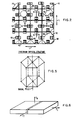
- a third somewhat less common metallic structure is the hexagonal close-packed crystal structure, as seen in Fig. 5.
- Zirconium, titanium and magnesium have this crystal structure at room temperature.
- the crystal structure of hexagonal close-packed materials like zirconium are not as symmetrical as that of body-centered and face-centered crystal structures. This means that when these materials are deformed during normal metal working processes, such as sheet or tube fabrication, the deformation process can only occur in a limited number of directions on an atomic scale because of different atom densities in different directions.
- the net result is that the deformed material is anisotropic, i.e., it has different texture (grain orientation) and different mechanical properties in different directions.
- materials which have different textures (grain orientations) and different properties in different directions such as zirconium and its alloys are known as anisotropic materials.
- the f-factor is the fraction of crystals aligned with their [0001] axis (or basal pole seen in Fig. 5) parallel to a given direction, assuming that the material is represented as a single crystal.
- F N , F T and F L represent the fraction of [0001] crystal axes aligned in three principal plate directions: normal (N), transverse (T) and rolling (L) directions.
- Values of f of 0 and 1.0 indicate perfect alignment of the [0001] crystal directions perpendicular or parallel, respectively, to the direction of interest, or given direction.
- f in the three principal directions must be unity. Normally, upon irradiation of the zirconium material, directions having values approaching 0.33 show no change in dimensions whereas those that have values approaching zero show the maximum growth and those t hat have values approaching one show the maximum shrinkage.
- orientation parameter herein referred to as the "f-factor”
- the improvement of the present invention is to provide fully recrystallized zirconium alloy or Zircaloy grid straps 40 in the grid 16 which have "f-factor" values of 0.45 and higher in generally orthogonal, longitudinal directions L (Fig. 2), values less than 0.25 in the strap height direction H (Figs. 3 and 4), and values of approximately 0.6 in the thickness direction.
- the generally orthogonal, longitudinal directions L of the grid straps 40 extend along a cross-section through the cells 42 of the grid 16, whereas the height direction of the straps 40 extend along the axes of the cells 42 along which the fuel rods 18 are received through the cells.
- the value of "f" in each longitudinal direction L is most important, the value of "f” in the height direction H is only moderately important and the value of "f” in the strap thickness direction is relatively unimportant.
- the values preferably should be fairly high in the longitudinal direction (0.4-0.5) and relatively low (0.2-0.3) in the height direction consistent with strap fabrication difficulty. It is noted that the more highly textured (grain oriented) the product, the more difficult it is to fabricate so that a reasonable compromise must be made.
- the grid cell size can be expected to decrease approximately 0.06% due to irradiation shrinkage which is approximately 0.4 mil in a typical PWR (pressurized water reactor) fuel assembly.
- the cold-worked spring growth would be greater than the recrystallization annealed wall because of the cold working and the fact that it is longer.
- the net result is approximately 0.1% delta growth of the spring which means that the spring will project into the cell slightly more. The net result is that contact is maintained between the grid and the fuel rod which prevent fretting.
- the springs 44 and dimples 46 when oriented axially in the direction of the strap height H, as seen in Figs. 3 and 4, will have projected lengths which are longer than the height of the openings of the strap 40 at the opposite ends of which the springs and dimples are attached. The material of the springs 44 and dimples 46 will thus grow in length in the strap height direction more than the remaining material of the strap 40 will grow in height in the strap height direction.
- the irradiation growth in length of the spring 44 and dimple 46 is calculated to be 1.25% versus 1% for the strap 40 in the height direction and the net result is that the spring and dimple will project farther against the fuel rod 18 by about one mil.
Landscapes
- Physics & Mathematics (AREA)
- Engineering & Computer Science (AREA)
- Plasma & Fusion (AREA)
- General Engineering & Computer Science (AREA)
- High Energy & Nuclear Physics (AREA)
- Fuel Cell (AREA)
- Monitoring And Testing Of Nuclear Reactors (AREA)
- Solid Fuels And Fuel-Associated Substances (AREA)
Applications Claiming Priority (2)
| Application Number | Priority Date | Filing Date | Title |
|---|---|---|---|
| US786986 | 1985-10-15 | ||
| US06/786,986 US4678632A (en) | 1985-06-05 | 1985-10-15 | Nuclear fuel assembly grid with predetermined grain orientation |
Publications (3)
| Publication Number | Publication Date |
|---|---|
| EP0220060A2 true EP0220060A2 (fr) | 1987-04-29 |
| EP0220060A3 EP0220060A3 (en) | 1988-05-25 |
| EP0220060B1 EP0220060B1 (fr) | 1992-01-15 |
Family
ID=25140117
Family Applications (1)
| Application Number | Title | Priority Date | Filing Date |
|---|---|---|---|
| EP86308007A Expired - Lifetime EP0220060B1 (fr) | 1985-10-15 | 1986-10-15 | Grilles de support pour un assemblage de combustible |
Country Status (6)
| Country | Link |
|---|---|
| US (1) | US4678632A (fr) |
| EP (1) | EP0220060B1 (fr) |
| JP (1) | JPS6288990A (fr) |
| KR (1) | KR870004456A (fr) |
| CN (1) | CN86107200A (fr) |
| DE (1) | DE3683440D1 (fr) |
Cited By (3)
| Publication number | Priority date | Publication date | Assignee | Title |
|---|---|---|---|---|
| EP0405172A1 (fr) * | 1989-06-28 | 1991-01-02 | Westinghouse Electric Corporation | Tubage en zircaloy présentant une texture radiale à crête unique |
| RU2195721C2 (ru) * | 2000-06-13 | 2002-12-27 | Открытое акционерное общество "Новосибирский завод химконцентратов" | Способ изготовления дистанционирующей решетки из циркониевого сплава |
| FR2860803A1 (fr) * | 2003-10-08 | 2005-04-15 | Cezus Co Europ Zirconium | Procede d'elaboration d'un produit plat en alliage de zirconium, produit plat ainsi obtenu et grille de reacteur de centrale nucleaire realisee a partir de ce produit plat |
Families Citing this family (19)
| Publication number | Priority date | Publication date | Assignee | Title |
|---|---|---|---|---|
| US5024426A (en) * | 1989-03-17 | 1991-06-18 | Advanced Nuclear Fuels Corporation | Bimetallic spring member for radiation environment |
| EP0689209A1 (fr) * | 1990-11-28 | 1995-12-27 | Hitachi, Ltd. | Procédé d'exploitation d'un réacteur nucléaire comportant plusieurs enveloppes d'assemblages combustibles et de fabrication de telles enveloppes |
| US5350161A (en) * | 1991-02-26 | 1994-09-27 | Combustion Engineering, Inc. | Nuclear reactor grid strip cantilever spring with nonuniform material characteristics |
| US6606369B1 (en) | 2002-03-06 | 2003-08-12 | Westinghouse Electric Company Llc | Nuclear reactor with improved grid |
| US6819733B2 (en) | 2002-05-15 | 2004-11-16 | Westinghouse Electric Company Llc | Fuel assembly and associated grid for nuclear reactor |
| US20070218353A1 (en) * | 2005-05-12 | 2007-09-20 | Straubel Jeffrey B | System and method for inhibiting the propagation of an exothermic event |
| US20070009787A1 (en) | 2005-05-12 | 2007-01-11 | Straubel Jeffrey B | Method and apparatus for mounting, cooling, connecting and protecting batteries |
| US7623612B2 (en) * | 2006-03-27 | 2009-11-24 | Westinghouse Electric Co. Llc | Bi-alloy spacer grid and associated methods |
| FR2909798A1 (fr) * | 2006-12-11 | 2008-06-13 | Areva Np Sas | Procede de conception d'un assemblage de combustible optimise en fonction des contraintes d'utilisation en reacteur nucleaire a eau legere,et assemblage de combustible en resultant. |
| US8758924B2 (en) * | 2007-06-18 | 2014-06-24 | Tesla Motors, Inc. | Extruded and ribbed thermal interface for use with a battery cooling system |
| US20080311468A1 (en) * | 2007-06-18 | 2008-12-18 | Weston Arthur Hermann | Optimized cooling tube geometry for intimate thermal contact with cells |
| US8263250B2 (en) * | 2007-06-18 | 2012-09-11 | Tesla Motors, Inc. | Liquid cooling manifold with multi-function thermal interface |
| US8116423B2 (en) | 2007-12-26 | 2012-02-14 | Thorium Power, Inc. | Nuclear reactor (alternatives), fuel assembly of seed-blanket subassemblies for nuclear reactor (alternatives), and fuel element for fuel assembly |
| UA98370C2 (ru) | 2007-12-26 | 2012-05-10 | Ториум Пауэр Инк. | Ядерный реактор (варианты), топливная сборка из зажигающе-воспроизводящих модулей для ядерного реактора (варианты) и топливный элемент топливной сборки |
| JP5755568B2 (ja) | 2008-12-25 | 2015-07-29 | トリウム・パワー、インクThorium Power,Inc. | 軽水炉核燃料集合体および軽水炉 |
| US10170207B2 (en) | 2013-05-10 | 2019-01-01 | Thorium Power, Inc. | Fuel assembly |
| US10192644B2 (en) | 2010-05-11 | 2019-01-29 | Lightbridge Corporation | Fuel assembly |
| WO2011143172A1 (fr) | 2010-05-11 | 2011-11-17 | Thorium Power, Inc. | Assemblage de combustible à noyau d'alliage de combustibles métalliques et son procédé de fabrication |
| CN110164567B (zh) * | 2018-03-30 | 2023-01-17 | 吉林农业大学 | 一种压水堆燃料组件格架 |
Family Cites Families (4)
| Publication number | Priority date | Publication date | Assignee | Title |
|---|---|---|---|---|
| BE623232A (fr) * | 1961-10-13 | |||
| US4770847A (en) * | 1982-06-01 | 1988-09-13 | General Electric Company | Control of differential growth in nuclear reactor components by control of metallurgical conditions |
| US4474730A (en) * | 1982-08-05 | 1984-10-02 | Westinghouse Electric Corp. | Nuclear fuel spacer grid |
| SE453441B (sv) * | 1985-07-09 | 1988-02-01 | Asea Atom Ab | Spridare for sammanhallning och fixering av langstreckta brenslestavar till knippen inskjutbara i en brenslepatron till en kernreaktor |
-
1985
- 1985-10-15 US US06/786,986 patent/US4678632A/en not_active Expired - Fee Related
-
1986
- 1986-10-13 CN CN198686107200A patent/CN86107200A/zh active Pending
- 1986-10-13 KR KR1019860008552A patent/KR870004456A/ko not_active Withdrawn
- 1986-10-15 EP EP86308007A patent/EP0220060B1/fr not_active Expired - Lifetime
- 1986-10-15 JP JP61246445A patent/JPS6288990A/ja active Pending
- 1986-10-15 DE DE8686308007T patent/DE3683440D1/de not_active Expired - Lifetime
Cited By (6)
| Publication number | Priority date | Publication date | Assignee | Title |
|---|---|---|---|---|
| EP0405172A1 (fr) * | 1989-06-28 | 1991-01-02 | Westinghouse Electric Corporation | Tubage en zircaloy présentant une texture radiale à crête unique |
| RU2195721C2 (ru) * | 2000-06-13 | 2002-12-27 | Открытое акционерное общество "Новосибирский завод химконцентратов" | Способ изготовления дистанционирующей решетки из циркониевого сплава |
| FR2860803A1 (fr) * | 2003-10-08 | 2005-04-15 | Cezus Co Europ Zirconium | Procede d'elaboration d'un produit plat en alliage de zirconium, produit plat ainsi obtenu et grille de reacteur de centrale nucleaire realisee a partir de ce produit plat |
| WO2005035817A3 (fr) * | 2003-10-08 | 2006-05-26 | Cezus Co Europ Zirconium | Procede d'elaboration d'un produit plat en alliage de zirconium, produit plat ainsi obtenu et grille de reacteur de centrale nucleaire realisee a partir de ce produit plat |
| KR101108935B1 (ko) * | 2003-10-08 | 2012-01-31 | 꽁빠니 유로삔느 뒤 지르꼬니움 세쥐 | 편평 지르코늄 합금 제품을 제조하는 방법과, 이로 인해얻어진 편평 제품 및 이러한 편평 제품으로부터 제조된원자력 발전소 반응기 그리드 |
| US8137488B2 (en) | 2003-10-08 | 2012-03-20 | Compagnie Europeenne Du Zirconium Cezus | Method of producing a flat zirconium alloy product, flat product thus obtained and a nuclear plant reactor grid which is made from said flat product |
Also Published As
| Publication number | Publication date |
|---|---|
| CN86107200A (zh) | 1987-04-01 |
| DE3683440D1 (de) | 1992-02-27 |
| US4678632A (en) | 1987-07-07 |
| EP0220060B1 (fr) | 1992-01-15 |
| EP0220060A3 (en) | 1988-05-25 |
| KR870004456A (ko) | 1987-05-09 |
| JPS6288990A (ja) | 1987-04-23 |
Similar Documents
| Publication | Publication Date | Title |
|---|---|---|
| EP0220060B1 (fr) | Grilles de support pour un assemblage de combustible | |
| US4957697A (en) | Nuclear fuel rod support grid with generally S-shaped spring structures | |
| US4885127A (en) | Nuclear fuel rod support grid with attachable spring and dimple support spacers | |
| US5596615A (en) | Fuel assembly for nuclear reactor and manufacturing method thereof | |
| US5265137A (en) | Wear resistant nuclear fuel assembly components | |
| EP0475159B1 (fr) | Composition de matériau zirlo et procédé de fabrication | |
| EP2267726A2 (fr) | Coeur de réacteur à eau légère et assemblage de combustible | |
| US3719560A (en) | Fuel assembly for a nuclear reactor using zirconium alloy clad fuel rods | |
| US4659541A (en) | Nuclear fuel rod support grid with improved multiple dimple arrangement | |
| EP0254096A2 (fr) | Réacteur à eau bouillante comportant une grille d'espacement de barres de combustible positionnée axialement | |
| JPS6214086A (ja) | スペ−サ | |
| US4314884A (en) | Nuclear fuel assembly | |
| WO2002003393A2 (fr) | Grille support d'espacement pour assemblage de combustible de reacteur a eau sous pression | |
| EP0712938A1 (fr) | Alliage de zirconium | |
| US5872826A (en) | Fuel assembly channel box having burnable poison | |
| EP2365490A2 (fr) | Dispositif de support de barreau de combustible anti-usure à ressort fractionné | |
| JPH0573194B2 (fr) | ||
| JP2693512B2 (ja) | 原子炉の燃料組立体用直交支持グリッドを製造する方法 | |
| US7127024B2 (en) | Fuel element for a pressurized water reactor | |
| US3804708A (en) | Nuclear reactor fuel rod | |
| EP0720767B1 (fr) | Barre de commande pour reacteur nucleaire | |
| US3813288A (en) | Nuclear reactor fuel assembly spacer grid | |
| JPH0463354B2 (fr) | ||
| SK279650B6 (sk) | Rozoberateľný jadrový palivový článok | |
| Smalley | Performance of Ag-In-Cd in pressurized water reactors |
Legal Events
| Date | Code | Title | Description |
|---|---|---|---|
| PUAI | Public reference made under article 153(3) epc to a published international application that has entered the european phase |
Free format text: ORIGINAL CODE: 0009012 |
|
| AK | Designated contracting states |
Kind code of ref document: A2 Designated state(s): BE DE ES FR GB IT SE |
|
| PUAL | Search report despatched |
Free format text: ORIGINAL CODE: 0009013 |
|
| AK | Designated contracting states |
Kind code of ref document: A3 Designated state(s): BE DE ES FR GB IT SE |
|
| 17P | Request for examination filed |
Effective date: 19881114 |
|
| 17Q | First examination report despatched |
Effective date: 19900712 |
|
| GRAA | (expected) grant |
Free format text: ORIGINAL CODE: 0009210 |
|
| AK | Designated contracting states |
Kind code of ref document: B1 Designated state(s): BE DE ES FR GB IT SE |
|
| PG25 | Lapsed in a contracting state [announced via postgrant information from national office to epo] |
Ref country code: IT Free format text: LAPSE BECAUSE OF FAILURE TO SUBMIT A TRANSLATION OF THE DESCRIPTION OR TO PAY THE FEE WITHIN THE PRE;WARNING: LAPSES OF ITALIAN PATENTS WITH EFFECTIVE DATE BEFORE 2007 MAY HAVE OCCURRED AT ANY TIME BEFORE 2007. THE CORRECT EFFECTIVE DATE MAY BE DIFFERENT FROM THE ONE RECORDED.SCRIBED TIME-LIMIT Effective date: 19920115 Ref country code: BE Effective date: 19920115 |
|
| ET | Fr: translation filed | ||
| REF | Corresponds to: |
Ref document number: 3683440 Country of ref document: DE Date of ref document: 19920227 |
|
| PG25 | Lapsed in a contracting state [announced via postgrant information from national office to epo] |
Ref country code: ES Free format text: LAPSE BECAUSE OF FAILURE TO SUBMIT A TRANSLATION OF THE DESCRIPTION OR TO PAY THE FEE WITHIN THE PRESCRIBED TIME-LIMIT Effective date: 19920426 |
|
| PGFP | Annual fee paid to national office [announced via postgrant information from national office to epo] |
Ref country code: ES Payment date: 19921015 Year of fee payment: 7 |
|
| PG25 | Lapsed in a contracting state [announced via postgrant information from national office to epo] |
Ref country code: SE Effective date: 19921016 |
|
| PLBE | No opposition filed within time limit |
Free format text: ORIGINAL CODE: 0009261 |
|
| STAA | Information on the status of an ep patent application or granted ep patent |
Free format text: STATUS: NO OPPOSITION FILED WITHIN TIME LIMIT |
|
| 26N | No opposition filed | ||
| PG25 | Lapsed in a contracting state [announced via postgrant information from national office to epo] |
Ref country code: FR Effective date: 19930630 |
|
| PG25 | Lapsed in a contracting state [announced via postgrant information from national office to epo] |
Ref country code: DE Effective date: 19930701 |
|
| REG | Reference to a national code |
Ref country code: FR Ref legal event code: ST |
|
| EUG | Se: european patent has lapsed |
Ref document number: 86308007.3 Effective date: 19930510 |
|
| REG | Reference to a national code |
Ref country code: GB Ref legal event code: IF02 |
|
| PGFP | Annual fee paid to national office [announced via postgrant information from national office to epo] |
Ref country code: GB Payment date: 20041004 Year of fee payment: 19 |
|
| PG25 | Lapsed in a contracting state [announced via postgrant information from national office to epo] |
Ref country code: GB Free format text: LAPSE BECAUSE OF NON-PAYMENT OF DUE FEES Effective date: 20051015 |
|
| GBPC | Gb: european patent ceased through non-payment of renewal fee |
Effective date: 20051015 |