EP0220116A1 - Verfahren und Vorrichtung zum Überwachen einer Fahrzeugaufhängung mittels Messung des Reibungskoeffizienten des Dämpfers - Google Patents
Verfahren und Vorrichtung zum Überwachen einer Fahrzeugaufhängung mittels Messung des Reibungskoeffizienten des Dämpfers Download PDFInfo
- Publication number
- EP0220116A1 EP0220116A1 EP86402255A EP86402255A EP0220116A1 EP 0220116 A1 EP0220116 A1 EP 0220116A1 EP 86402255 A EP86402255 A EP 86402255A EP 86402255 A EP86402255 A EP 86402255A EP 0220116 A1 EP0220116 A1 EP 0220116A1
- Authority
- EP
- European Patent Office
- Prior art keywords
- sensor
- signal
- coefficient
- friction
- value
- Prior art date
- Legal status (The legal status is an assumption and is not a legal conclusion. Google has not performed a legal analysis and makes no representation as to the accuracy of the status listed.)
- Granted
Links
Images

Classifications
-
- G—PHYSICS
- G01—MEASURING; TESTING
- G01M—TESTING STATIC OR DYNAMIC BALANCE OF MACHINES OR STRUCTURES; TESTING OF STRUCTURES OR APPARATUS, NOT OTHERWISE PROVIDED FOR
- G01M17/00—Testing of vehicles
- G01M17/007—Wheeled or endless-tracked vehicles
- G01M17/04—Suspension or damping
-
- B—PERFORMING OPERATIONS; TRANSPORTING
- B60—VEHICLES IN GENERAL
- B60G—VEHICLE SUSPENSION ARRANGEMENTS
- B60G17/00—Resilient suspensions having means for adjusting the spring or vibration-damper characteristics, for regulating the distance between a supporting surface and a sprung part of vehicle or for locking suspension during use to meet varying vehicular or surface conditions, e.g. due to speed or load
- B60G17/015—Resilient suspensions having means for adjusting the spring or vibration-damper characteristics, for regulating the distance between a supporting surface and a sprung part of vehicle or for locking suspension during use to meet varying vehicular or surface conditions, e.g. due to speed or load the regulating means comprising electric or electronic elements
-
- B—PERFORMING OPERATIONS; TRANSPORTING
- B60—VEHICLES IN GENERAL
- B60Q—ARRANGEMENT OF SIGNALLING OR LIGHTING DEVICES, THE MOUNTING OR SUPPORTING THEREOF OR CIRCUITS THEREFOR, FOR VEHICLES IN GENERAL
- B60Q9/00—Arrangement or adaptation of signal devices not provided for in one of main groups B60Q1/00 - B60Q7/00, e.g. haptic signalling
-
- F—MECHANICAL ENGINEERING; LIGHTING; HEATING; WEAPONS; BLASTING
- F16—ENGINEERING ELEMENTS AND UNITS; GENERAL MEASURES FOR PRODUCING AND MAINTAINING EFFECTIVE FUNCTIONING OF MACHINES OR INSTALLATIONS; THERMAL INSULATION IN GENERAL
- F16F—SPRINGS; SHOCK-ABSORBERS; MEANS FOR DAMPING VIBRATION
- F16F9/00—Springs, vibration-dampers, shock-absorbers, or similarly-constructed movement-dampers using a fluid or the equivalent as damping medium
- F16F9/32—Details
- F16F9/3264—Arrangements for indicating, e.g. fluid level; Arrangements for checking dampers
-
- G—PHYSICS
- G07—CHECKING-DEVICES
- G07C—TIME OR ATTENDANCE REGISTERS; REGISTERING OR INDICATING THE WORKING OF MACHINES; GENERATING RANDOM NUMBERS; VOTING OR LOTTERY APPARATUS; ARRANGEMENTS, SYSTEMS OR APPARATUS FOR CHECKING NOT PROVIDED FOR ELSEWHERE
- G07C5/00—Registering or indicating the working of vehicles
- G07C5/08—Registering or indicating performance data other than driving, working, idle, or waiting time, with or without registering driving, working, idle or waiting time
Definitions
- the present invention relates to the control of the suspension of motor vehicles.
- suspensions of motor vehicles are generally composed, for each of the wheels, of an assembly, formed of a damper connected in parallel to a spring, disposed between the suspended masses and the unsprung masses of the vehicle.
- “Suspended masses” means all of the parts of the vehicle body which rest on the suspension; while non-suspended masses are understood to be all of the masses that are movable relative to the body, and in particular the wheels and suspension triangles. Where appropriate, the non-suspended masses also include the brakes and part of the shock absorbers.
- the primary function of the suspension spring is to limit the spread of vertical wheel movements to the vehicle body, in order to increase road comfort.
- the spring does not quickly return to its stable equilibrium position.
- the energy which it has stored tends to induce oscillations of the body as well as shocks and rebounds of the wheel on the ground during which this energy dissipates in heat.
- the most commonly used damper consists of a body rigidly connected to the unsprung masses, which defines a main chamber filled with hydraulic fluid, a sliding rod, rigidly connected to the body of the vehicle and a foraminous piston cali- b res and equipped with valves, which moves in the main chamber and a secondary chamber, called compensation, partially filled with gas and fluid LY draulic which communicates with the main bedroom via valves.
- shock absorbers for vehicle suspension have been proposed.
- the present invention is not limited to a particular type of shock absorber.
- the function of the shock absorber is therefore to transform the mechanical energy of movement of its rod into heat. For this, the shock absorber opposes the movement
- the linear curve area corresponds to the operating conditions where the hydraulic fluid circulates through the valves.
- strain gauges to measure the forces exerted at various points of the suspension.
- Such devices are for example described in patents US-A-4,458,234, DE-A-2,351,862 and DE-A-2,341,423.
- These documents are content to evoke, for the exploitation of electrical signals delivered by the gauges, the arrangement of these gauges in bridge or even the measurement of the amplitude variations, positive or negative, of the forces exerted on the damper and / or the spring.
- These provisions only provide overall information on the operation of the suspension and do not allow the delivery of precise and reliable information on the state of the suspension, useful to the driver.
- the problem posed is therefore to design a measurement technique making it possible to reliably, economically and continuously detect, using boatable means, the state of the suspension.
- Step iii) consisting in determining the value of the coefficient of friction of the damper can consist either of a calculation on the basis of discrete values of the signals generated by the first and the second sensors, or by processing an analog signal generated by each of these sensors.
- the method according to the present invention further comprises the additional step of comparing the value of the coefficient of friction C determined in step iii) with a threshold value and of displaying an alarm when the determined value of the coefficient friction falls below the threshold value.
- the aforementioned comparison step intended to define the need to view an alarm, uses several threshold values corresponding respectively to the characteristic zones of the force / speed curve of the damper, for example 4 values threshold.
- control method according to the present invention comprises the additional step of exploiting, for example by viewing analog information representative of the coefficient of friction C.
- the present invention also relates to the application of the above-mentioned device to the control of slave suspensions.
- these sensors 11, 12 are arranged at the upper attachment point of the spring 2 and the damper 3 respectively.
- the first sensor 11 can be a sensor associated with the spring 2 and sensitive to the relative displacement of the suspended masses / unsprung masses, for example a piezoelectric cell disposed between two turns of the suspension spring, in the case a coil spring, or a force sensor interposed between the suspension spring2 and the unsprung masses 4.
- the second sensor 12 can be a force sensor disposed at the level of the attachment. bottom of shock absorber 3.
- a pair of sensors respectively generating a signal dependent on the force exerted by the spring 2 and a signal dependent on the force exerted on the damper 3 are associated with each suspension.
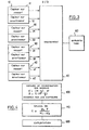
- the signals generated by the sensors 11, 12, 21, 22, 31, 32, 41, 42 are applied to processing means 50 which themselves control operating means, for example display means 60.
- the first sensor 11 is then chosen to generate a signal a representative of the elongation of the spring 2, while the second sensor 12 is chosen to generate a signal B representative of the speed of movement of the rod of the damper 3 .
- These sensors can be formed for example from strain gauges or potentiometric sensors.
- the processing means 50 are then adapted to store two discrete values of the signal from each sensor 11,21,31,41 associated with the spring, and spaced by a time interval T.
- the processing means 50 are adapted to store two discrete values ⁇ 0 , a 1 representative of the elongation of the spring 2, at two instants spaced apart from the duration T.
- the processing means 50 are also adapted to store a discrete value ⁇ of the signal from each of the sensors 12,22,32,42 associated with the damper, simultaneously with the storage of one of the information items from the sensors 11, 21,31,41.
- the second step of the control method according to the present invention referenced 110 in FIG. 4 then consists in calculating the value of c, that is to say of the viscous coefficient of friction of the damper on the basis of the relationship (1) above.
- control method according to the present invention ends with an operating step, for example an operating display referenced schematically 120 in FIG. 4.
- This display step 120 can be the subject of various variants.
- the operating step 120 consists in comparing the value of the coefficient of friction c calculated using the formula (1) with a threshold value and in displaying an alarm when the calculated value of the friction coefficient falls below the threshold value.
- threshold values are used for this, corresponding respectively to the characteristic zones of the force / speed curve of the damper, for example 4 threshold values.
- chaaue part of the curve force applied to the rod / speed of the rod, corresponding respectively to the relaxation and compression of the he shock absorber has two zones, one linear, the other of the parabolic type.
- the operating step 120 consists in using directly, for example by visualization, analog information representative of the coefficient of friction c.
- the first sensor 11 is then a sensor generating a signal y representative of the rate of deformation of the spring 2, while the second sensor 12 is a sensor generating a signal representative of the acceleration of the damper rod.
- These two sensors can be formed for example of inductive or capacitive sensors.
- a derivation of the analog signal Y from the first sensor 11 associated with the spring makes it possible to obtain a signal y of the form:
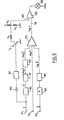
- This circuit comprises three inputs 1 1 , 1 2 and 1 3 which respectively receive the signals y, log K and ⁇ -The analog signal Y is first of all applied to an operator 150 which determines the first derivative of this signal, ie ⁇ ; then to an operator 151 which determines the logarithm of the signal to be log ⁇ ; and finally, to an operator 152 which reverses the signal and delivers a signal of the form - loa ⁇ .
- the analodic signal ⁇ is first of all applied to an operator 160 which operates on the signal ⁇ a phase shift identical to that imposed on the signal y by the operators 150,152; then to an operator 161 which determines the logarithm of the signal to be log ⁇ .
- the three signals (-log ⁇ ), (log K) and (log ⁇ ) are applied to the respective inputs of a summator 170 with three inputs which delivers at its output a signal of the log c type corresponding to the relation (11).
- the signal log c can be used to directly display analog information representative of the coefficient of friction c.
- the value of the coefficient c thus calculated can be compared with a threshold value, with alarm display when the calculated value of the coefficient of friction c falls below the threshold value.
- FIG. 5 shows schematically an example of means making it possible to thus define two comparison thresholds, one serving as a threshold during a phase of compression of the shock absorber, the other serving as a threshold during a phase of the shock absorber.
- the log signal c is applied to the first input 191 of a comparator 190.
- This comparator 190 receives on its second input 192 the comparison threshold signal.
- comparator 190 attacks a display indicator 195.
- the comparison threshold is defined by the potential present at the midpoint of a resistive bridge R 2- R 3 connected to the input 192.
- the comparison threshold is defined by the potential present at the midpoint of the resistive bridge comprising on the one hand the resistance R 2 , on the other hand share and in parallel the resistors R 1 and R 3 .
- the grounding of the resistance R 1 is controlled by the transistor T 1 type NPN whose emitter is connected to the ground and the collector to the resistance R 1 .
- the base of transistor T is controlled by a diode 180 and a follower amplifier 181.
- the diode 180 receives the signal Y on its anode.
- the diode 180 is conducting in the compression phase and on the other hand blocked in the expansion phase due to the reversal of direction of the electrical signal generated Y.
- the cathode of the diode 180 drives the follower amplifier 181, the output of which saturates the base of the transistor T 1 , in the compression phase to make the latter passing.
- the present invention can in particular be applied for the control of servo-controlled suspensions, for example to control the hardness of the suspension, or even to operate a trim of the vehicle.
- the control device may also include an output for diagnostic station making it possible to trace the characteristic curve of the coefficient of friction c.
- the present invention finds application both in the case of independent wheel suspensions and in the case of rigid bridge suspensions.
- the display means 60 are adapted to deliver specific information for each of the suspensions, either in the form of an alarm indicator in the case of a comparison with a threshold value as previously mentioned, or in the form of a analog display of each of the measured coefficients c.
Landscapes
- Engineering & Computer Science (AREA)
- Mechanical Engineering (AREA)
- General Engineering & Computer Science (AREA)
- Physics & Mathematics (AREA)
- General Physics & Mathematics (AREA)
- Human Computer Interaction (AREA)
- Vehicle Body Suspensions (AREA)
Applications Claiming Priority (2)
| Application Number | Priority Date | Filing Date | Title |
|---|---|---|---|
| FR8515082A FR2588659B1 (fr) | 1985-10-11 | 1985-10-11 | Procede et dispositif de controle d'une suspension de vehicule par mesure du coefficient de frottement de l'amortisseur |
| FR8515082 | 1985-10-11 |
Publications (2)
| Publication Number | Publication Date |
|---|---|
| EP0220116A1 true EP0220116A1 (de) | 1987-04-29 |
| EP0220116B1 EP0220116B1 (de) | 1990-03-28 |
Family
ID=9323738
Family Applications (1)
| Application Number | Title | Priority Date | Filing Date |
|---|---|---|---|
| EP19860402255 Expired - Lifetime EP0220116B1 (de) | 1985-10-11 | 1986-10-10 | Verfahren und Vorrichtung zum Überwachen einer Fahrzeugaufhängung mittels Messung des Reibungskoeffizienten des Dämpfers |
Country Status (3)
| Country | Link |
|---|---|
| EP (1) | EP0220116B1 (de) |
| DE (1) | DE3669921D1 (de) |
| FR (1) | FR2588659B1 (de) |
Cited By (4)
| Publication number | Priority date | Publication date | Assignee | Title |
|---|---|---|---|---|
| FR2834338A1 (fr) * | 2001-12-28 | 2003-07-04 | Peugeot Citroen Automobiles Sa | Procede et dispositif de diagnostic d'amortisseurs de vehicule |
| WO2013044508A1 (zh) * | 2011-09-30 | 2013-04-04 | 中联重工科技发展股份有限公司 | 一种运行设备的故障预警提示系统 |
| CN107253468A (zh) * | 2016-03-01 | 2017-10-17 | 诸建芬 | 一种用于汽车减震器的失效检测及报警系统 |
| CN109564091A (zh) * | 2016-08-02 | 2019-04-02 | 日立汽车系统株式会社 | 立体相机 |
Families Citing this family (1)
| Publication number | Priority date | Publication date | Assignee | Title |
|---|---|---|---|---|
| RU2152016C1 (ru) * | 1996-02-06 | 2000-06-27 | Научно-производственное объединение прикладной механики | Способ определения демпфирующих свойств амортизаторов из композиционных материалов при ударных воздействиях |
Citations (4)
| Publication number | Priority date | Publication date | Assignee | Title |
|---|---|---|---|---|
| DE2043526A1 (de) * | 1970-09-02 | 1972-03-09 | Daimler-Benz Ag, 7000 Stuttgart | Hydropneumatische Federung |
| GB2093946A (en) * | 1981-02-26 | 1982-09-08 | Itt Ind Ltd | Monitoring shock absorbers |
| US4458234A (en) * | 1981-05-14 | 1984-07-03 | Brisard Gerard J | On-board apparatus for monitoring the condition of shock absorbers |
| DE3316011A1 (de) * | 1983-05-03 | 1984-11-08 | Volkswagenwerk Ag | Anordnung zur ueberwachung des betriebszustands eines schwingungsdaempfers in einer radaufhaengung |
-
1985
- 1985-10-11 FR FR8515082A patent/FR2588659B1/fr not_active Expired
-
1986
- 1986-10-10 EP EP19860402255 patent/EP0220116B1/de not_active Expired - Lifetime
- 1986-10-10 DE DE8686402255T patent/DE3669921D1/de not_active Expired - Lifetime
Patent Citations (4)
| Publication number | Priority date | Publication date | Assignee | Title |
|---|---|---|---|---|
| DE2043526A1 (de) * | 1970-09-02 | 1972-03-09 | Daimler-Benz Ag, 7000 Stuttgart | Hydropneumatische Federung |
| GB2093946A (en) * | 1981-02-26 | 1982-09-08 | Itt Ind Ltd | Monitoring shock absorbers |
| US4458234A (en) * | 1981-05-14 | 1984-07-03 | Brisard Gerard J | On-board apparatus for monitoring the condition of shock absorbers |
| DE3316011A1 (de) * | 1983-05-03 | 1984-11-08 | Volkswagenwerk Ag | Anordnung zur ueberwachung des betriebszustands eines schwingungsdaempfers in einer radaufhaengung |
Cited By (8)
| Publication number | Priority date | Publication date | Assignee | Title |
|---|---|---|---|---|
| FR2834338A1 (fr) * | 2001-12-28 | 2003-07-04 | Peugeot Citroen Automobiles Sa | Procede et dispositif de diagnostic d'amortisseurs de vehicule |
| WO2013044508A1 (zh) * | 2011-09-30 | 2013-04-04 | 中联重工科技发展股份有限公司 | 一种运行设备的故障预警提示系统 |
| CN107253468A (zh) * | 2016-03-01 | 2017-10-17 | 诸建芬 | 一种用于汽车减震器的失效检测及报警系统 |
| CN107264213A (zh) * | 2016-03-01 | 2017-10-20 | 诸建芬 | 一种汽车减震器失效检测及报警系统 |
| CN107264213B (zh) * | 2016-03-01 | 2019-10-08 | 浙江庄普模具有限公司 | 一种汽车减震器失效检测及报警系统 |
| CN107253468B (zh) * | 2016-03-01 | 2019-10-11 | 明光市龙腾科技工贸有限公司 | 一种用于汽车减震器的失效检测及报警系统 |
| CN109564091A (zh) * | 2016-08-02 | 2019-04-02 | 日立汽车系统株式会社 | 立体相机 |
| CN109564091B (zh) * | 2016-08-02 | 2021-04-02 | 日立汽车系统株式会社 | 立体相机 |
Also Published As
| Publication number | Publication date |
|---|---|
| EP0220116B1 (de) | 1990-03-28 |
| FR2588659A1 (fr) | 1987-04-17 |
| FR2588659B1 (fr) | 1989-09-22 |
| DE3669921D1 (de) | 1990-05-03 |
Similar Documents
| Publication | Publication Date | Title |
|---|---|---|
| EP0220115B1 (de) | Verfahren und Vorrichtung zur Überwachung einer Fahrzeugaufhängung mittels Messung des Reibungskoeffizienten des Stossdämpfers | |
| US6701235B2 (en) | Suspension control system | |
| US5859692A (en) | Height sensor and air spring apparatus incorporating the same in the air chamber | |
| US4830399A (en) | Elastic connection between at least two rigid parts | |
| US4770438A (en) | Automotive suspension control system with road-condition-dependent damping characteristics | |
| EP0401111A1 (de) | Vorrichtung zur Niveau- und/oder Volumenmessung einer Flüssigkeit mit einer kapazitiven Sonde | |
| EP0474826A1 (de) | Schwingungsdämpfer mit doppler-aufnehmer für die flüssigkeitsgeschwindigkeit. | |
| FR2506014A1 (fr) | Appareil de bord pour controler les amortisseurs de suspension | |
| FR2719000A1 (fr) | Système de suspension actif, en particulier pour automobiles. | |
| FR2794067A1 (fr) | Dispositif d'estimation de la quantite d'etat cinetique pour un vehicule a moteur et methode de mise en oeuvre | |
| KR940005430A (ko) | 차륜상에서의 차량변위의 판정장치와 그 장치를 포함하는 운전시스템 및 차량 | |
| CN101583507A (zh) | 用于确定路面状况的方法和生成车辆使用日志的方法 | |
| EP0220116A1 (de) | Verfahren und Vorrichtung zum Überwachen einer Fahrzeugaufhängung mittels Messung des Reibungskoeffizienten des Dämpfers | |
| EP0220985B1 (de) | Verfahren und Vorrichtung zur Überwachung einer Fahrzeugaufhängung mittels Messung des Dämpfungsfaktors einer Schwingung der Aufhängung | |
| FR2520870A1 (fr) | Dispositif permettant de mesurer la charge repartie sur les moyens de roulement d'un train d'atterrissage d'un aeronef | |
| FR2867152A1 (fr) | Procede de controle de l'amortissement de vibrations d'un helicoptere et dispositif mettant en oeuvre le procede | |
| EP0466604B1 (de) | Vorrichtung zur Messung der relativen Lage von 2 zueinander beweglichen Teilen, die durch wenigstens einen teleskopischen Stossdämpfer verbunden sind | |
| EP0223653B1 (de) | Verfahren und Vorrichtung zur Überwachung einer Fahrzeugaufhängung mittels Überwachung der Strassenhaftung | |
| FR2668600A1 (fr) | Procede et dispositif de verification de l'efficacite d'une suspension de vehicule par mesure du dephasage entre un mouvement imprime a la roue et la trajectoire de cette meme roue. | |
| EP0439401A1 (de) | Scherenstromabnehmer mit gedämpfter Kopfaufhängung | |
| EP0504478A1 (de) | Ladegewicht-Anzeigevorrichtung für Fahrzeuge | |
| FR2925680A1 (fr) | Procede pour detecter l'etat d'usure d'un amortisseur d'un vehicule automobile. | |
| FR2693273A1 (fr) | Procédé et dispositif pour la détermination de l'accélération d'une superstructure de véhicule. | |
| FR2834338A1 (fr) | Procede et dispositif de diagnostic d'amortisseurs de vehicule | |
| CA1289221C (en) | Elastic connection between at least two rigid parts |
Legal Events
| Date | Code | Title | Description |
|---|---|---|---|
| PUAI | Public reference made under article 153(3) epc to a published international application that has entered the european phase |
Free format text: ORIGINAL CODE: 0009012 |
|
| AK | Designated contracting states |
Kind code of ref document: A1 Designated state(s): DE GB IT |
|
| 17P | Request for examination filed |
Effective date: 19870921 |
|
| 17Q | First examination report despatched |
Effective date: 19881110 |
|
| GRAA | (expected) grant |
Free format text: ORIGINAL CODE: 0009210 |
|
| AK | Designated contracting states |
Kind code of ref document: B1 Designated state(s): DE GB IT |
|
| PG25 | Lapsed in a contracting state [announced via postgrant information from national office to epo] |
Ref country code: IT Free format text: LAPSE BECAUSE OF FAILURE TO SUBMIT A TRANSLATION OF THE DESCRIPTION OR TO PAY THE FEE WITHIN THE PRESCRIBED TIME-LIMIT;WARNING: LAPSES OF ITALIAN PATENTS WITH EFFECTIVE DATE BEFORE 2007 MAY HAVE OCCURRED AT ANY TIME BEFORE 2007. THE CORRECT EFFECTIVE DATE MAY BE DIFFERENT FROM THE ONE RECORDED. Effective date: 19900328 Ref country code: GB Effective date: 19900328 |
|
| REF | Corresponds to: |
Ref document number: 3669921 Country of ref document: DE Date of ref document: 19900503 |
|
| GBV | Gb: ep patent (uk) treated as always having been void in accordance with gb section 77(7)/1977 [no translation filed] | ||
| PLBE | No opposition filed within time limit |
Free format text: ORIGINAL CODE: 0009261 |
|
| STAA | Information on the status of an ep patent application or granted ep patent |
Free format text: STATUS: NO OPPOSITION FILED WITHIN TIME LIMIT |
|
| 26N | No opposition filed | ||
| PGFP | Annual fee paid to national office [announced via postgrant information from national office to epo] |
Ref country code: DE Payment date: 19921121 Year of fee payment: 7 |
|
| PG25 | Lapsed in a contracting state [announced via postgrant information from national office to epo] |
Ref country code: DE Effective date: 19940701 |