EP0223653B1 - Verfahren und Vorrichtung zur Überwachung einer Fahrzeugaufhängung mittels Überwachung der Strassenhaftung - Google Patents
Verfahren und Vorrichtung zur Überwachung einer Fahrzeugaufhängung mittels Überwachung der Strassenhaftung Download PDFInfo
- Publication number
- EP0223653B1 EP0223653B1 EP86402252A EP86402252A EP0223653B1 EP 0223653 B1 EP0223653 B1 EP 0223653B1 EP 86402252 A EP86402252 A EP 86402252A EP 86402252 A EP86402252 A EP 86402252A EP 0223653 B1 EP0223653 B1 EP 0223653B1
- Authority
- EP
- European Patent Office
- Prior art keywords
- fact
- suspension
- sensor
- oscillations
- filtered signal
- Prior art date
- Legal status (The legal status is an assumption and is not a legal conclusion. Google has not performed a legal analysis and makes no representation as to the accuracy of the status listed.)
- Expired - Lifetime
Links
Images


Classifications
-
- B—PERFORMING OPERATIONS; TRANSPORTING
- B60—VEHICLES IN GENERAL
- B60Q—ARRANGEMENT OF SIGNALLING OR LIGHTING DEVICES, THE MOUNTING OR SUPPORTING THEREOF OR CIRCUITS THEREFOR, FOR VEHICLES IN GENERAL
- B60Q9/00—Arrangement or adaptation of signal devices not provided for in one of main groups B60Q1/00 - B60Q7/00, e.g. haptic signalling
-
- F—MECHANICAL ENGINEERING; LIGHTING; HEATING; WEAPONS; BLASTING
- F16—ENGINEERING ELEMENTS AND UNITS; GENERAL MEASURES FOR PRODUCING AND MAINTAINING EFFECTIVE FUNCTIONING OF MACHINES OR INSTALLATIONS; THERMAL INSULATION IN GENERAL
- F16F—SPRINGS; SHOCK-ABSORBERS; MEANS FOR DAMPING VIBRATION
- F16F9/00—Springs, vibration-dampers, shock-absorbers, or similarly-constructed movement-dampers using a fluid or the equivalent as damping medium
- F16F9/32—Details
- F16F9/3264—Arrangements for indicating, e.g. fluid level; Arrangements for checking dampers
-
- G—PHYSICS
- G01—MEASURING; TESTING
- G01M—TESTING STATIC OR DYNAMIC BALANCE OF MACHINES OR STRUCTURES; TESTING OF STRUCTURES OR APPARATUS, NOT OTHERWISE PROVIDED FOR
- G01M17/00—Testing of vehicles
- G01M17/007—Wheeled or endless-tracked vehicles
- G01M17/04—Suspension or damping
-
- G—PHYSICS
- G07—CHECKING-DEVICES
- G07C—TIME OR ATTENDANCE REGISTERS; REGISTERING OR INDICATING THE WORKING OF MACHINES; GENERATING RANDOM NUMBERS; VOTING OR LOTTERY APPARATUS; ARRANGEMENTS, SYSTEMS OR APPARATUS FOR CHECKING NOT PROVIDED FOR ELSEWHERE
- G07C5/00—Registering or indicating the working of vehicles
- G07C5/08—Registering or indicating performance data other than driving, working, idle, or waiting time, with or without registering driving, working, idle or waiting time
Definitions
- the present invention relates to the control of the suspension of motor vehicles.
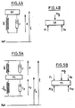
- suspensions of motor vehicles are generally composed, for each of the wheels, of an assembly, formed of a damper connected in parallel to a spring, disposed between the suspended masses and the unsprung masses of the vehicle.
- “Suspended masses” means all of the parts of the vehicle body which rest on the suspension; while non-suspended masses are understood to be all of the masses that are movable relative to the body, and in particular the wheels and suspension triangles. Where appropriate, the unsprung masses also include the brakes and part of the shock absorbers.
- the primary function of the suspension spring is to limit the spread of vertical wheel movements to the vehicle body, in order to increase road comfort.
- the spring does not quickly return to its stable equilibrium position.
- the energy which it has stored tends to induce oscillations of the body as well as shocks and rebounds of the wheel on the ground during which this energy dissipates in heat.
- shock absorber consists of a body rigidly connected to the unsprung masses, which defines a main chamber filled with hydraulic fluid, a sliding rod, rigidly linked to the body of the vehicle and to a pierced piston. calibrated holes fitted with valves, which moves in the main chamber, and a secondary chamber, called a compensation chamber, partially filled with gas and hydraulic fluid, which communicates with the main chamber via valves.
- shock absorbers for vehicle suspension have been proposed.
- the present invention is not limited to a particular type of shock absorber.
- the function of the shock absorber is therefore to transform the mechanical energy of movement of its rod into heat.
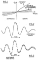
- the shock absorber opposes the movement of its rod a force substantially proportional to the speed of the latter.
- the linear curve area corresponds to the operating conditions where the hydraulic fluid circulates through the valves.
- strain gauges to measure the forces exerted at various points of the suspension.
- Such devices are for example described in patents US-A 4,458,234, DE-A 2,351,862 and DE-A 2,341,423.
- These documents are content to evoke, for the exploitation of the electrical signals delivered by the gauges, the arrangement of these bridge gauges or even the measurement of variations in amplitude, positive or negative, of the forces exerted on the damper and / or the spring.
- These provisions only provide overall information on the operation of the suspension and do not make it possible to deliver precise and reliable information on the state of the suspension useful to the driver.
- the problem posed is to design a measurement technique making it possible to detect reliably, economically and continuously, using boatable means, the state of the suspension.
- One of the main goals of. the present invention is to design economic measurement means, suitable for being installed in series on motor vehicles without significantly increasing the cost price thereof.
- step ii) of filtering can be carried out by the sensor itself working in a narrow frequency range centered on the frequency of the oscillations generated by the unsprung masses and the spring effect of the tire.
- This process makes it possible to detect a lack of grip due to excessive wear of one of the suspension components, this regardless of the road profile and the type of suspension.
- a damper in good condition suitably attenuates parasitic oscillations due to the unsprung masses of the vehicle and to the spring effect of the tire.
- a shock absorber exhibiting wear does not correctly attenuate these parasitic oscillations, and consequently does not avoid the rebounds responsible for the detachment of the wheel relative to the ground, and therefore does not ensure correct handling. .
- the method also includes the intermediate step of rectifying the filtered signal before processing.
- the present invention also relates to a device for controlling the suspension of a vehicle for implementing the aforementioned method,
- the formulas (13) and (14) therefore give the changes in the movement of the body (X) and the movement of the wheel (X 2 ) with respect to an absolute reference and as a function of the profile of the road (X 1 ).
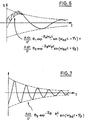
- the cut-off frequency of 1 Hz is created by the suspended masses of the vehicle and the suspension spring.
- the cutoff frequency of 12 Hz is generated by the unsprung masses of the vehicle and the spring effect of the tire.
- the signals s (t) and s 2 (t) are shown diagrammatically in FIGS. 6 and 7.
- the parameters W A , W B , Z A and Ze are represented in FIG. 8 as a function of the viscous coefficient of friction.
- This sensor 10 can be a sensor sensitive to the relative displacement of suspended masses / unsprung masses.
- the sensor 10 can be arranged between two turns of the suspension spring, in the case of a coil spring.
- This sensor 10 can also be formed by a force sensor interposed between the suspension spring and the suspended masses or the unsprung masses.
- the sensor 10 can for example be formed from a piezoelectric cell.
- the electrical signal generated at the output of the sensor 10 is applied to a bandpass filter 20 which has for function of retaining the oscillations of a frequency of the order of 12 Hz generated by the unsprung masses of the vehicle and the spring effect of the tire and of eliminating the low frequency oscillations of 1 Hz created by the suspended masses of the vehicle and the suspension spring as well as the frequencies higher than the frequencies generated by the unsprung masses and the spring effect of the tire.
- the filter 20 can for example have a pass band ranging from 9 Hz to 15 Hz.
- the filtered electrical signal from filter 20 is then directed to a rectification cell 30.
- the rectified filtered signal from cell 30 is then applied to the first input 52 of a comparator 50.
- the latter receives on its second input 51 an electrical signal coming from the output 46 of a reference generator 45.
- the electrical signal generated at the output 46 of the generator 45 corresponds to the amplitude threshold with respect to which it is desired to compare the electrical signal generated by the sensor 10.
- the output 71 of this main timer 70 increases linearly as a function of time.
- the secondary timer 60 has a time setpoint slightly greater than the period of the oscillations generated by the unsprung masses and the spring effect of the tire.
- the main timer 70 is reset.
- the output 71 of the main timer 70 is connected to the first input 82 of a second comparator 80.
- the second input 81 of the comparator 80 is also connected to an output 47 of the reference generator 45.
- the signal from the output 47 of the generator 45 corresponds to the time setpoint of the main timer 70, that is to say the time necessary for the linear signal at the output of the timer 70 to reach the value of this signal.
- comparator 80 which switches if the main delay setpoint is reached, that is to say if the signal at the output of timer 70 reaches the value of the setpoint signal 47, is connected to an amplifier 90 which attacks an operating system, for example a display system 95 making it possible to display an alarm when the comparators 50 and 80 have detected the exceeding of said threshold value 46 by the peaks of the electrical signal coming from the sensor 10, and the maintenance of this signal above said threshold throughout the duration of the main delay 70 defined by setpoint 47.
- an operating system for example a display system 95 making it possible to display an alarm when the comparators 50 and 80 have detected the exceeding of said threshold value 46 by the peaks of the electrical signal coming from the sensor 10, and the maintenance of this signal above said threshold throughout the duration of the main delay 70 defined by setpoint 47.
- FIG. 10 can be the subject of numerous variant embodiments.
- the first step 100 of the method according to the present invention consists in detecting the electrical signal coming from the sensor sensitive to the oscillations of the suspension.
- This electrical signal is then filtered in step 110 and then rectified in step 120.
- the subsequent step is a test step 130 consisting in detecting whether the filtered and rectified signal exceeds a threshold A.
- step 130 is repeated.
- the main timer T i is initialized in step 140 and the secondary timer T 2 is initialized in step 150.
- a new test step 160 checks whether the electrical signal still exceeds the predetermined threshold A.
- test step 180 which detects whether the setpoint of the main time delay Ti is reached.
- measurement and display means are associated with each suspension.
- FIG. 10 three measurement chains 11, 12, 13 associated with respective suspensions, identical to the means described above, and comprising the elements 10, 20, 30, 50, 60, 70, 80, 90.
- the elements 20, 30, 50, 60, 80 and 90 may be common to the various measurement chains, the signals from the various sensors being processed in sequence by multiplexing.
- This device comprises two input terminals referenced e 1 and e 2 on the left of FIG. 12, to which is intended to be connected the aforementioned sensor 10.
- the senor 10 is connected to the input terminals e 1 , e 2 via an impedance matching stage, constituted for example by 'a follower amplifier.
- the sensor 10 thus attacks a filter 20 comprising a capacitor C 1 and a resistor R 1 connected in series to the terminals e 1 and e 2 , the resistor R 1 being placed on the ground side of the assembly.
- the output of the filter 20 is defined by the terminal common to the capacitor C 1 and the resistor R i .
- filter 20 is not limiting. This filter could for example be replaced by an active filter having an attenuation slope of at least - 3 dB.
- This output of the filter 20 is connected to the input of a rectification cell 30 and more precisely to the anode of a diode D 1 whose cathode is connected to the input of an RC cell in T referenced schematically 60 , forming secondary timer.
- This cell 60 comprises a resistor R 2 and a capacitor C 2 connected in series between the cathode of the diode D 1 and the earth of the assembly, the capacitor C 2 being placed on the earth side of the assembly, as well as a resistor R 3 connected to the common terminal to the resistor R 2 and to the capacitor C 2 .
- An assembly comprising in series an adjustable resistor R 14 and a diode Ds is connected in parallel with the series assembly comprising the resistor R 2 and the diode D 1 , the cathode of the diode D 5 being connected to the anode of the diode Sun.
- the output of the RC cell 60 is taken on the second terminal of the resistor Rs.
- This second terminal of the resistor R 3 is connected to the inverting input of an operational amplifier OP 1 playing the role of the aforementioned comparator 50.
- This operational amplifier OP 1 is connected to the midpoint of a divider bridge comprising a fixed resistor R 4 and a variable resistor R s connected in series between the ground of the assembly and a positive supply terminal + Vcc .
- the output of the operational amplifier OP 1 drives an RC cell forming the main timer 70.
- the output of the operational amplifier OP 1 is connected to the positive supply terminal + V cc via a resistor Rs.
- the output of the operational amplifier OP 1 is also connected to the first terminal of a resistor R 7 and to the first terminal of a resistor R 8 .
- the second terminal of the resistor R 7 is connected to the anode of a diode D 2 , the cathode of which is connected to the input of the RC cell 70.
- the second terminal of the adjustable resistance Ra is connected to the cathode of a diode D 3 , the anode of which is connected to the aforementioned input of the RC cell 70.
- This RC 70 cell comprises a capacitor C 3 connected between on the one hand the point common to the cathode of the diode D 2 and the anode of the diode D 3 and on the other hand the ground of the assembly, as well as a resistance R 9 , a first terminal of which is connected to the same common point.
- the second terminal of the resistor R 9 constitutes the output of the timing cell RC 70.
- This second terminal of the resistor R 9 is connected to the inverting input of an operational amplifier OP 2 playing the role of the aforementioned comparator 80.
- This operational amplifier OP 2 is connected to the midpoint of a resistive bridge comprising a fixed resistor R 10 and a variable resistor R 11 connected in series between the ground of the assembly and the positive supply terminal + V cc .
- the output of the amplifier OP 2 is connected to the base of an NPNT transistor 1 , the emitter of which is connected to the ground of the assembly.
- the base of the transistor T 1 is also connected to the midpoint of a bias bridge comprising a resistor R 13 and a resistor R 12 connected in series between the ground of the assembly and the positive supply terminal + Vcc.
- the collector of transistor T i is connected to an operating device, for example a display indicator L.
- the collector of transistor T 1 is connected to the cathode of a diode D 4 , the anode of which is connected to a first terminal of the display indicator L
- the second terminal of the display indicator L is connected to a positive supply terminal V.
- the potential generated at the midpoint of the resistive bridge R 4 - R s , which is applied to the non-inverting input of the comparator OP 1 defines the amplitude threshold A to which we want to compare the detected signal.
- the potential defined at the midpoint of the resistive bridge R 10 -R 11 and applied to the non-inverting input of the comparator OP 2 defines the set value of the main timer 70.
- the output of the operational amplifier OP 1 remains at the high level.
- the capacitor C 3 is charged via the diode D 2 and the comparator 80 which receives on its inverting input a high potential sees its output at the low level.
- the transistor T 1 is therefore blocked and the display indicator 95 is not supplied.
- the diode D 2 is then blocked and the capacitor C 3 begins to discharge via the diode Ds.
- the output of the amplifier OP1 goes back to the high level to quickly recharge the capacitor C 3 via the diode D 2 and reset the main timer 70.
- the switching of the output of the comparator 80 to the high level in fact means that the peaks of the signal delivered by the sensor 10 have exceeded the amplitude threshold defined at the midpoint of the resistive bridge R 4 -R s during the setpoint duration defined by the potential present at the midpoint of the resistive bridge R i oR n .
- the display means 95 are adapted to issue a specific alarm for each of the suspensions.
- the present invention finds application both in the case of independent wheel suspensions and in the case of rigid bridge suspensions.
Landscapes
- Engineering & Computer Science (AREA)
- Mechanical Engineering (AREA)
- General Engineering & Computer Science (AREA)
- Physics & Mathematics (AREA)
- General Physics & Mathematics (AREA)
- Human Computer Interaction (AREA)
- Vehicle Body Suspensions (AREA)
Claims (10)
Applications Claiming Priority (2)
| Application Number | Priority Date | Filing Date | Title |
|---|---|---|---|
| FR8515081 | 1985-10-11 | ||
| FR8515081A FR2588658B1 (fr) | 1985-10-11 | 1985-10-11 | Procede et dispositif de controle d'une suspension de vehicule par controle de l'adherence |
Publications (2)
| Publication Number | Publication Date |
|---|---|
| EP0223653A1 EP0223653A1 (de) | 1987-05-27 |
| EP0223653B1 true EP0223653B1 (de) | 1990-03-28 |
Family
ID=9323737
Family Applications (1)
| Application Number | Title | Priority Date | Filing Date |
|---|---|---|---|
| EP86402252A Expired - Lifetime EP0223653B1 (de) | 1985-10-11 | 1986-10-10 | Verfahren und Vorrichtung zur Überwachung einer Fahrzeugaufhängung mittels Überwachung der Strassenhaftung |
Country Status (3)
| Country | Link |
|---|---|
| EP (1) | EP0223653B1 (de) |
| DE (1) | DE3669923D1 (de) |
| FR (1) | FR2588658B1 (de) |
Families Citing this family (3)
| Publication number | Priority date | Publication date | Assignee | Title |
|---|---|---|---|---|
| RU2164675C2 (ru) * | 1999-04-23 | 2001-03-27 | Московский государственный автомобильно-дорожный институт (Технический университет) | Способ диагностики управляющих устройств и систем автотранспортных средств |
| SE0203382L (sv) | 2002-11-15 | 2004-05-16 | Volvo Lastvagnar Ab | System och metod för att diagnostisera stötdämpare |
| US11433731B2 (en) | 2017-11-28 | 2022-09-06 | Volvo Truck Corporation | Method for determining a functional status of a vehicle shock absorber arrangement |
Citations (1)
| Publication number | Priority date | Publication date | Assignee | Title |
|---|---|---|---|---|
| DE2362661A1 (de) * | 1973-07-09 | 1975-06-26 | Volkswagenwerk Ag | Verfahren zur pruefung der funktionsfaehigkeit von stossdaempfern |
Family Cites Families (6)
| Publication number | Priority date | Publication date | Assignee | Title |
|---|---|---|---|---|
| DE2905931C2 (de) * | 1979-02-16 | 1985-12-19 | Daimler-Benz Ag, 7000 Stuttgart | Vorrichtung zur Überwachung von Stoßdämpfern und Reifenluftdruck von Fahrzeugrädern |
| GB2093946B (en) * | 1981-02-26 | 1984-05-23 | Itt Ind Ltd | Monitoring shock absorbers |
| FR2506014B1 (fr) * | 1981-05-14 | 1987-08-21 | Brisard Gerard | Appareil de bord pour controler les amortisseurs de suspension |
| DE3316011A1 (de) * | 1983-05-03 | 1984-11-08 | Volkswagenwerk Ag | Anordnung zur ueberwachung des betriebszustands eines schwingungsdaempfers in einer radaufhaengung |
| US4770438A (en) * | 1984-01-20 | 1988-09-13 | Nissan Motor Co., Ltd. | Automotive suspension control system with road-condition-dependent damping characteristics |
| IT1196700B (it) * | 1984-05-11 | 1988-11-25 | Fiat Auto Spa | Dispositivo per il controllo degli ammortizzatori delle sospensioni particolarmente per autovetture |
-
1985
- 1985-10-11 FR FR8515081A patent/FR2588658B1/fr not_active Expired - Lifetime
-
1986
- 1986-10-10 EP EP86402252A patent/EP0223653B1/de not_active Expired - Lifetime
- 1986-10-10 DE DE8686402252T patent/DE3669923D1/de not_active Expired - Lifetime
Patent Citations (1)
| Publication number | Priority date | Publication date | Assignee | Title |
|---|---|---|---|---|
| DE2362661A1 (de) * | 1973-07-09 | 1975-06-26 | Volkswagenwerk Ag | Verfahren zur pruefung der funktionsfaehigkeit von stossdaempfern |
Also Published As
| Publication number | Publication date |
|---|---|
| EP0223653A1 (de) | 1987-05-27 |
| DE3669923D1 (de) | 1990-05-03 |
| FR2588658A1 (fr) | 1987-04-17 |
| FR2588658B1 (fr) | 1990-03-09 |
Similar Documents
| Publication | Publication Date | Title |
|---|---|---|
| EP0220115B1 (de) | Verfahren und Vorrichtung zur Überwachung einer Fahrzeugaufhängung mittels Messung des Reibungskoeffizienten des Stossdämpfers | |
| CH647596A5 (fr) | Procede pour determiner le volume de liquide contenu dans un recipient ferme et dispositif pour la mise en oeuvre de ce procede. | |
| FR2559864A1 (fr) | Isolateur de vibrations | |
| FR2584344A1 (fr) | Circuit de codage de la valeur de deux grandeurs mesurees dans un pneumatique et dispositif de surveillance des pneumatiques utilisant un tel circuit | |
| FR3030373A1 (fr) | Procede d'estimation de la fiabilite de mesures de capteurs de roue d'un vehicule et systeme de mise en oeuvre | |
| EP0223653B1 (de) | Verfahren und Vorrichtung zur Überwachung einer Fahrzeugaufhängung mittels Überwachung der Strassenhaftung | |
| FR2874205A1 (fr) | Procede et dispositif de suspension active d'un aeronef a voilure tournante | |
| US3939692A (en) | Assembly for testing shock absorbers incorporated in vehicles | |
| EP0220985B1 (de) | Verfahren und Vorrichtung zur Überwachung einer Fahrzeugaufhängung mittels Messung des Dämpfungsfaktors einer Schwingung der Aufhängung | |
| FR2556471A1 (fr) | Dispositif de detection de bulles d'air | |
| CA2283136A1 (fr) | Insert de securite generant un signal vibratoire transversal et dispositif de detection de la mise en appui d'un pneumatique sur un insert | |
| EP0220116B1 (de) | Verfahren und Vorrichtung zum Überwachen einer Fahrzeugaufhängung mittels Messung des Reibungskoeffizienten des Dämpfers | |
| FR2520870A1 (fr) | Dispositif permettant de mesurer la charge repartie sur les moyens de roulement d'un train d'atterrissage d'un aeronef | |
| FR2918172A1 (fr) | Dispositif et procede de surveillance de l'etat vibratoire d'une machine tournante. | |
| EP1571517A1 (de) | Steuerungsverfahren und Vorrichtung für die Dämpfung der Schwingungen eines Hubschraubers | |
| FR2676400A1 (fr) | Amortisseur de vehicule a coefficient reglable d'amortissement et procede de reglage. | |
| EP0736781A1 (de) | Niederfrequenz-seismischer Fühler | |
| EP1766338B1 (de) | Verfahren zum testen einer messvorrichtung mit variabler kapazität | |
| FR2694398A1 (fr) | Procédé et dispositifs de détection de la mise en appui d'un pneumatique sur un appui de sécurité. | |
| FR2664538A1 (fr) | Dispositif de determination de la position relative de deux pieces montees mobiles l'une par rapport a l'autre, et reliees par au moins un amortisseur telescopique. | |
| FR2796744A1 (fr) | Systeme de transmission de valeurs de mesure | |
| EP0483016A1 (de) | Verfahren und Vorrichtung zur Kontrolle des Wirkungsgrades einer Aufhängung in situ | |
| EP3470884B1 (de) | Filterverfahren eines antwortsignals eines geophons, und entsprechender sensor | |
| EP0605298B1 (de) | Verfahren und Sensor zur Erfassung der Dichte einer Flüssigkeit und Gerät zur Massenbestimmung unter Verwendung eines solchen Sensors | |
| US4254970A (en) | Vehicle suspension using pressurized Bourdon tubes |
Legal Events
| Date | Code | Title | Description |
|---|---|---|---|
| PUAI | Public reference made under article 153(3) epc to a published international application that has entered the european phase |
Free format text: ORIGINAL CODE: 0009012 |
|
| AK | Designated contracting states |
Kind code of ref document: A1 Designated state(s): DE GB IT |
|
| 17P | Request for examination filed |
Effective date: 19870921 |
|
| 17Q | First examination report despatched |
Effective date: 19881110 |
|
| GRAA | (expected) grant |
Free format text: ORIGINAL CODE: 0009210 |
|
| AK | Designated contracting states |
Kind code of ref document: B1 Designated state(s): DE GB IT |
|
| PG25 | Lapsed in a contracting state [announced via postgrant information from national office to epo] |
Ref country code: IT Free format text: LAPSE BECAUSE OF FAILURE TO SUBMIT A TRANSLATION OF THE DESCRIPTION OR TO PAY THE FEE WITHIN THE PRESCRIBED TIME-LIMIT;WARNING: LAPSES OF ITALIAN PATENTS WITH EFFECTIVE DATE BEFORE 2007 MAY HAVE OCCURRED AT ANY TIME BEFORE 2007. THE CORRECT EFFECTIVE DATE MAY BE DIFFERENT FROM THE ONE RECORDED. Effective date: 19900328 Ref country code: GB Effective date: 19900328 |
|
| REF | Corresponds to: |
Ref document number: 3669923 Country of ref document: DE Date of ref document: 19900503 |
|
| GBV | Gb: ep patent (uk) treated as always having been void in accordance with gb section 77(7)/1977 [no translation filed] | ||
| PLBE | No opposition filed within time limit |
Free format text: ORIGINAL CODE: 0009261 |
|
| STAA | Information on the status of an ep patent application or granted ep patent |
Free format text: STATUS: NO OPPOSITION FILED WITHIN TIME LIMIT |
|
| 26N | No opposition filed | ||
| PGFP | Annual fee paid to national office [announced via postgrant information from national office to epo] |
Ref country code: DE Payment date: 19921121 Year of fee payment: 7 |
|
| PG25 | Lapsed in a contracting state [announced via postgrant information from national office to epo] |
Ref country code: DE Effective date: 19940701 |