EP0220347A1 - Dispositif de nettoyage de la paroi interieure d'un tube - Google Patents
Dispositif de nettoyage de la paroi interieure d'un tube Download PDFInfo
- Publication number
- EP0220347A1 EP0220347A1 EP85307586A EP85307586A EP0220347A1 EP 0220347 A1 EP0220347 A1 EP 0220347A1 EP 85307586 A EP85307586 A EP 85307586A EP 85307586 A EP85307586 A EP 85307586A EP 0220347 A1 EP0220347 A1 EP 0220347A1
- Authority
- EP
- European Patent Office
- Prior art keywords
- tube
- cleaners
- buoyancy
- cleaning
- flow
- Prior art date
- Legal status (The legal status is an assumption and is not a legal conclusion. Google has not performed a legal analysis and makes no representation as to the accuracy of the status listed.)
- Granted
Links
- 238000004140 cleaning Methods 0.000 title claims abstract description 120
- 230000007935 neutral effect Effects 0.000 claims abstract description 26
- 229920001971 elastomer Polymers 0.000 claims abstract description 21
- 230000003134 recirculating effect Effects 0.000 claims abstract description 14
- 239000000806 elastomer Substances 0.000 claims abstract description 9
- 230000004087 circulation Effects 0.000 claims abstract description 6
- 230000004044 response Effects 0.000 claims abstract description 5
- 238000005188 flotation Methods 0.000 claims description 27
- 230000004888 barrier function Effects 0.000 claims description 24
- XLYOFNOQVPJJNP-UHFFFAOYSA-N water Substances O XLYOFNOQVPJJNP-UHFFFAOYSA-N 0.000 claims description 21
- 238000000034 method Methods 0.000 claims description 13
- 239000012528 membrane Substances 0.000 claims description 10
- 230000007423 decrease Effects 0.000 claims description 7
- 239000012530 fluid Substances 0.000 claims description 7
- 239000007787 solid Substances 0.000 claims description 6
- 230000006835 compression Effects 0.000 claims description 5
- 238000007906 compression Methods 0.000 claims description 5
- 238000002347 injection Methods 0.000 claims description 5
- 239000007924 injection Substances 0.000 claims description 5
- 230000002093 peripheral effect Effects 0.000 claims description 2
- 239000000306 component Substances 0.000 claims 3
- 239000006260 foam Substances 0.000 claims 2
- 210000004379 membrane Anatomy 0.000 claims 2
- 229910052729 chemical element Inorganic materials 0.000 claims 1
- 238000007789 sealing Methods 0.000 claims 1
- 238000009826 distribution Methods 0.000 abstract description 15
- FBWNMEQMRUMQSO-UHFFFAOYSA-N tergitol NP-9 Chemical compound CCCCCCCCCC1=CC=C(OCCOCCOCCOCCOCCOCCOCCOCCOCCO)C=C1 FBWNMEQMRUMQSO-UHFFFAOYSA-N 0.000 abstract 1
- 239000000463 material Substances 0.000 description 13
- 241001131696 Eurystomus Species 0.000 description 9
- 239000000498 cooling water Substances 0.000 description 8
- 238000010276 construction Methods 0.000 description 7
- 239000007788 liquid Substances 0.000 description 6
- 238000004519 manufacturing process Methods 0.000 description 5
- 230000000694 effects Effects 0.000 description 4
- 238000000926 separation method Methods 0.000 description 4
- 229920005830 Polyurethane Foam Polymers 0.000 description 3
- 208000036366 Sensation of pressure Diseases 0.000 description 3
- 230000009471 action Effects 0.000 description 3
- 239000007789 gas Substances 0.000 description 3
- 239000011496 polyurethane foam Substances 0.000 description 3
- 230000008901 benefit Effects 0.000 description 2
- 239000004215 Carbon black (E152) Substances 0.000 description 1
- 229910000831 Steel Inorganic materials 0.000 description 1
- 238000005299 abrasion Methods 0.000 description 1
- 239000002253 acid Substances 0.000 description 1
- 230000003466 anti-cipated effect Effects 0.000 description 1
- 230000009286 beneficial effect Effects 0.000 description 1
- 230000005540 biological transmission Effects 0.000 description 1
- 229940105289 carbon black Drugs 0.000 description 1
- 235000019241 carbon black Nutrition 0.000 description 1
- 239000006229 carbon black Substances 0.000 description 1
- 230000001413 cellular effect Effects 0.000 description 1
- 239000011538 cleaning material Substances 0.000 description 1
- 238000000576 coating method Methods 0.000 description 1
- 238000002485 combustion reaction Methods 0.000 description 1
- 239000000356 contaminant Substances 0.000 description 1
- 230000008602 contraction Effects 0.000 description 1
- 238000001816 cooling Methods 0.000 description 1
- 239000012809 cooling fluid Substances 0.000 description 1
- 238000005260 corrosion Methods 0.000 description 1
- 230000007797 corrosion Effects 0.000 description 1
- 230000006378 damage Effects 0.000 description 1
- 230000003247 decreasing effect Effects 0.000 description 1
- 230000001419 dependent effect Effects 0.000 description 1
- 230000008021 deposition Effects 0.000 description 1
- 239000006185 dispersion Substances 0.000 description 1
- 239000013536 elastomeric material Substances 0.000 description 1
- 230000008030 elimination Effects 0.000 description 1
- 238000003379 elimination reaction Methods 0.000 description 1
- 239000006261 foam material Substances 0.000 description 1
- 230000005484 gravity Effects 0.000 description 1
- 229930195733 hydrocarbon Natural products 0.000 description 1
- 150000002430 hydrocarbons Chemical class 0.000 description 1
- 239000011261 inert gas Substances 0.000 description 1
- 238000009413 insulation Methods 0.000 description 1
- 230000013011 mating Effects 0.000 description 1
- 230000008520 organization Effects 0.000 description 1
- 239000004814 polyurethane Substances 0.000 description 1
- 230000002250 progressing effect Effects 0.000 description 1
- 238000005086 pumping Methods 0.000 description 1
- 238000005096 rolling process Methods 0.000 description 1
- 239000004576 sand Substances 0.000 description 1
- 229920006395 saturated elastomer Polymers 0.000 description 1
- 239000010959 steel Substances 0.000 description 1
- 230000032258 transport Effects 0.000 description 1
- 238000009827 uniform distribution Methods 0.000 description 1
Images


Classifications
-
- F—MECHANICAL ENGINEERING; LIGHTING; HEATING; WEAPONS; BLASTING
- F28—HEAT EXCHANGE IN GENERAL
- F28G—CLEANING OF INTERNAL OR EXTERNAL SURFACES OF HEAT-EXCHANGE OR HEAT-TRANSFER CONDUITS, e.g. WATER TUBES OR BOILERS
- F28G1/00—Non-rotary, e.g. reciprocated, appliances
- F28G1/12—Fluid-propelled scrapers, bullets, or like solid bodies
-
- B—PERFORMING OPERATIONS; TRANSPORTING
- B08—CLEANING
- B08B—CLEANING IN GENERAL; PREVENTION OF FOULING IN GENERAL
- B08B9/00—Cleaning hollow articles by methods or apparatus specially adapted thereto
- B08B9/02—Cleaning pipes or tubes or systems of pipes or tubes
- B08B9/027—Cleaning the internal surfaces; Removal of blockages
- B08B9/04—Cleaning the internal surfaces; Removal of blockages using cleaning devices introduced into and moved along the pipes
- B08B9/053—Cleaning the internal surfaces; Removal of blockages using cleaning devices introduced into and moved along the pipes moved along the pipes by a fluid, e.g. by fluid pressure or by suction
- B08B9/055—Cleaning the internal surfaces; Removal of blockages using cleaning devices introduced into and moved along the pipes moved along the pipes by a fluid, e.g. by fluid pressure or by suction the cleaning devices conforming to, or being conformable to, substantially the same cross-section of the pipes, e.g. pigs or moles
-
- B—PERFORMING OPERATIONS; TRANSPORTING
- B08—CLEANING
- B08B—CLEANING IN GENERAL; PREVENTION OF FOULING IN GENERAL
- B08B9/00—Cleaning hollow articles by methods or apparatus specially adapted thereto
- B08B9/02—Cleaning pipes or tubes or systems of pipes or tubes
- B08B9/027—Cleaning the internal surfaces; Removal of blockages
- B08B9/04—Cleaning the internal surfaces; Removal of blockages using cleaning devices introduced into and moved along the pipes
- B08B9/053—Cleaning the internal surfaces; Removal of blockages using cleaning devices introduced into and moved along the pipes moved along the pipes by a fluid, e.g. by fluid pressure or by suction
- B08B9/057—Cleaning the internal surfaces; Removal of blockages using cleaning devices introduced into and moved along the pipes moved along the pipes by a fluid, e.g. by fluid pressure or by suction the cleaning devices being entrained discrete elements, e.g. balls, grinding elements, brushes
Definitions
- the present invention relates to a system for cleaning the inside diameters in a bank of tubes in a heat exchanger system, tube cleaners for use therein and methods for their use.
- Heat exchangers of the type contemplated by the presented invention comprise condensers utilized in applications such as steam generating power plants.
- a condenser includes tubes arranged in a tube bundle. Water flowing through the condenser tube bundle picks up heat from condensing steam on a shell side or outside diameters of the tubes.
- a plurality of condensers may be installed in one power plant, each condenser having a large number of tubes.
- the selection of number of tubes and number of condensers is a function of the design parameters for each system. These design parameters include the amount of water to be pumped through the tubes, the temperature of steam contacting the tubes and various flow rates. According to R. J. Stoker and E. F.
- a nominal flow through the condensers could be 300,000 gallons per minute.
- 300,000 square feet of surface area in the one condenser are required for cooling. In a nominal design, this surface is provided using tubes 50 feet long and having an outside diameter of one inch. Since maximum surface area is provided by long, small diameter tubes, it is easy to see that individual condensers having 40,000 tubes in a bundle would not be uncommon.
- An established method of cleaning consists of circulating sponge rubber balls through the heat exchange unit.
- the balls are forced by pressure to traverse the tubes and each wipe the inside of the tube. While a sponge rubber ball will have only a minor effect on one pass, the balls are commonly maintained in circulation through several hundred or several thousand passes with the objective of cleaning the interior diameter of the tubes.
- Apparatus must be provided for collection the sponge rubber balls after they exit from the tubes, conducting them through a recirculation path and reinjecting them into a liquid stream for reintroduction into the tubes. Therefore, the art has developed various forms of cleaners and systems for circulating them repeatedly through tube bundles.
- the present invention seeks to provide advantages not found in the prior art and elimination of disadvantages as are included in the prior art further discussed here.
- the suitable device is a sieve means which may be formed as a "V" to intercept the outlet flow from the condenser when the system operates in a mode for recirculating the cleaning means.
- each leg of the "V" may be rotated so that the two legs are parallel and flow without intercepting the outlet from a condenser when a cleaning opeation is not being performed.
- Many other arrangements are provided in which a means intercepting the entire outlet from the condenser is positioned to intercept the flow and in which the intercepting means may be "feathered" to permit the flow to pass without being screened.
- the screens themselves create a pressure drop. They may be subject to clogging, depending on the nature of contaminants found in the cooling water to exacerbate the magnitude of the pressure drop.
- the above-described construction requires the use of strong, durable screens to withstand the full flow issuing from the condenser.
- the price of a cleaning system is considerable. In an exemplary 800 megawatt steam generating station built around 1975, a nominal price for the equipment attributable to the system for recirculating cleaning elements, separate and apart from the condensers themselves, was one million dollars. It is desirable to provide a system in which simpler construction is possible and in which it is not necessary to intercept the entire flow issuing from the condenser station.
- the cleaning balls themselves, many forms have been provided commonly utilizing sponge rubber of a slightly larger dimension than the inner diameter of the tube to be cleaned. Over a large number of recirculating passes through the tubes, the sponge rubber balls tend to remove undesired buildups in the interior of heat exchanger tubes. After separation from the outlet stream from the condenser, the cleaning elements are recirculated. A means for separating worn out balls which are decreased in size prior to delivery to the inlet stream to the condenser may be provided.
- the cleaning elements are normally unevenly distributed through the tubes within the banks in a condenser since the cleaning elements are heavier than water when recirculated and returned for introduction into tubes in a condenser.
- Upper tubes may not be cleaned effectively and eventually must be mechanically and/or chemically cleaned. Acid cleaning is a known form of cleaning. There is the attendant expense of the cleaning operation and significant "downtime" for the condenser, which often results in the shutting down of the power plant itself.
- the geometry of the cleaning elements can provide for difficulty and expense in their construction. It is desired to provide for the option of simplifying construction.
- Prior art refers to means used for cleaning inner diameters by many differnt terms, e.g. plug, pig, ball, etc. Such names will be referred to herein as tube cleaners.
- tube cleaners of the type described comprising a combinationm of a first variable buoyancy member means and second member not of variable buoyancy but for facilitating cleaning, whereby the entire structure is of variable buoyancy.
- tube cleaners of the type comprising a buoyancy member and a cleaning member which may be formed to have substantially neutral buoyancy in the above-described application and in which the buoyancy of individual tube cleaners is fixed.
- open cell e.g. sponge rubber, tube cleaners as variable buoyancy members.
- a cleaning system for circulation tube cleaners through condenser tubes, tube cleaners and a method for cleaning tube inside diameters in apparatus such as heat exchangers.
- Vertically disposed means intercept a portion of the flow from an outlet manifold of a condenser and deflect cleaning elements therefrom to conduit means.
- the conduit means direct cleaning elements to recirculation means and reinjection means which provide the cleaning elements to an inlet manifold for circulation through heat exchange elements.
- the recirculation means may include separator means for separating worn cleaning elements and may further include a deaeration chamber.
- Entraining means draw the cleaning elements into a stream and subject them to pressure wherein they are compressed and entrained for entry into the cleaning stream.
- the tube cleaners are made to have a density such that they approach neutral density under conditions expected to be encountered at the entry to condenser tubes.
- cleaning elements comprise closed cell material.
- An example is polyurethane foam.
- the cleaning element increases in density and decreases in buoyancy.
- Variation in buoyancy of the tube cleaners may be limited.
- the cleaning elements are formed so as to float at atmospheric pressure and to reach neutral buoyancy when compressed at expected pressures at the entrance to the heat exchange tubes. These tube cleaners float upon exiting from the outlet manifold.
- buoyancy of the cleaning elements is varied during the course of recirculation as described above. Further, cleaning elements having a diameter smaller than the inside diameter of the tubes may be inserted intentionally into the flow path of the cleaning purposes.
- Figure 1 is an elevation in schematic and partially in cross-sectional form of a system 1 in which tube cleaners elements 2 are circulated to clean inside diameters of tubes 3 in a condenser 4.
- a recirculation system 6 is operable to selectively return tube cleaners 2 which exit from the condenser 4 to the inlet thereof.
- the supply of cooling water is provided from an inlet conduit 10.
- the inlet conduit 10 can supply cooling water from a river, lake or other source. It should be realized that cooling water is an example of one suitable form of cooling fluid medium which can be circulated through the present system. Other media may be utilized. However, water will most commonly be provided in embodiments in which the condenser 4 is included in a steam power generating plant. Cooling water enters an inlet distribution head 12 communicating with the entry to each tube 3.
- An outlet conduit 11 receives cooling water from an outlet collection head 13 communicating with the tubes 3 and discharges the cooling water.
- the outlet conduit 11 also communicates with the recirculation system 6.
- the outlet conduit 11 may comprise a pipe, tunnel or an open trough or flume.
- the illustration in Figure 1 is intended to be representative of either.
- the cross-section of the outlet conduit 11 at Figure 1 may be either square or circular. Commonly, an open trough or tunnel will have a rectangular cross-section, and a pipe will have a circular cross-section.
- FIGS 2 and 3 which are partial cross-sectional illustrations of an elevation and a plan respectively along Lines 2-2 and 3-3 of Figure 1 illustrate one form of the interface between the outlet conduit 11 and the recirculation system 6.
- the interface means 20 comprises a barrier 25 for intercepting flow in the outlet conduit 11 in a manner described in further detail below and directing a portion thereof to a conduit 30 having an outlet 31 terminating in a deaeration tank 34.
- the deaeration tank 34 is of conventional construction including a liquid level controller 36 for controlling water level in the tank 34 by controlling valve means 37 operating pressure means 38.
- the deaerating tank 34 is operated in a conventional manner.
- the pressure means 38 is operated in a conventional manner.
- the pressure means 38 which may supply negative pressures such as a vacuum is operated to draw air off from the tank 34. In this manner, air is removed from the flow that is to be returned through the remainder of the recirculation system 6.
- aerating tank 34 Within the aerating tank 34 is an inlet 40 to a conduit 41 which conducts water and material entrained therein (such as tube cleaners 2) from the deaerating tank 34 pumped by a pump 43 to a conduit 44.
- a source 42 of make-up water is provided to provide a sufficient stream into which to entrain, pressurize and reinject the tube cleaners 2.
- the conduit 44 has an outlet 45 for injecting tube cleaners 2 in the flow path to the inlet 10 of the heat exchanger 1.
- variable buoyancy tube cleaners 2 are utilized which will have positive buoyancy upon reaching the outlet manifold 4 and outlet 11.
- the barrier 25 is formed to provide skimmer means positioned for intercepting a vertical extreme portion of flow in a hori zontal component of the flow direction from the outlet collection head 13.
- the barrier 25 is preferably a straight, rectangularly shaped wall member.
- the barrier 25 may be a V-shaped barrier when viewed in a direction normal to outlet flow and comprising first and second radial flanges.
- the barrier 25 is positioned extending across a top portion of the outlet 11.
- top portion contemplates a depth which corresponds to the expected depth to which tube cleaners are expected to be encountered.
- the barrier 25 is preferably positioned a distance from the outlet collection head 13 such that tube cleaners 2 will have an opportunity to float to the top of the water flow. It is significant that the barrier 25 and outlet conduit 30 may be formed to provide a minor portion, for example, as little as one or two percent of the outlet flow in the outlet 11 to the recirculation system 6.
- the barrier 25 may be of solid construction, such as a solid piece of steel.
- the barrier may be made at minimum cost to provide maximum strength. This is to be contrasted with extremely expensive and complex screen systems of the prior art.
- a screen system is of necessity difficult to provide in that a screen must be open enough to permit flow therethrough and yet must be strong enough to withstand the differential pressure thereacross.
- a screen also necessarily creates a back-pressure. Such a back-pressure is not produced by the present barrier system in an open flume.
- the back-pressure produced in a closed pipe embodiment is not significant since only a minority of the area of the cross-section of the pipe need be blocked this is extremely significant since in a nominal embodiment in an 800 megawatt power plant, for example, outlet flow in a nominal outlet pipe 11 may be 140,000 gallons per minute.
- the barrier 25 preferably extends to a point at which the conduit 30 intersects the outlet 11. From that point, the barrier 25 is angled with respect to the horizontal component of flow in the pipe 11. As the tube cleaners 2 are carried along in the flow and impact the barrier 25, the tube cleaners 2 are directed to the conduit 30.
- the angle at which the barrier 25 is placed with respect to the flow may be, for example, 45°.
- An optimal angle may be selec ted as a function of the geometry or geometries of the tube cleaners 2.
- the tube cleaners may not necessarily all be spherical. Further, different geometries of tube cleaners may be combined in the flow.
- the optimum angle is a function of the combination of tube cleaners 2 provided in the flow.
- One skilled in the art will know when the optimum angle is achieved in that the maximum number of tube cleaners reach the conduit 30 after striking the barrier 25 in a minimum time.
- the conduit 30 receives a flow of water and tube cleaners 2 and provides the flow to the deaeration tank 34.
- the pump 43 pumps flow therefrom.
- the tube cleaners 2 as entrained in the flow are then injected from the outlet 45 into the stream entering the inlet 10.
- Tube cleaners 2 are then dispersed throughout the inlet distribution head 12.
- the pressurization of the tube cleaners 2 to substantial neutral buoyancy is highly useful in that it helps assure a substantially even distribution of tube cleaners to all the tubes 3 in the heat exchanger 4. Turbulence in the inlet distribution head 12 further disperses the tube cleaners 2.
- the inlet distribution head 12 may be as high as 20 feet to accommodate all 40,000 tubes. This has resulted in prior art, conventional tube cleaning operations being relatively ineffective as applied to the upper tubes.
- the tubes cleaners 2 are forced under pressure through the tubes 3.
- the tube cleaners rub thereagainst. Only a minimum amount of cleaning takes place on one pass. It is contemplated that the tube cleaners 2 will be recirculated continuously through the heat exchanger except during cleaning system outages.
- each tube cleaner comprises a closed cell or closed cell material.
- the closed cell material is preferably an elastomer.
- An example of a closed cell material is polyurethane foam. This is to be contrasted with the common, open cell, sponge rubber tube cleaner of the prior art.
- the optimal density of foam material will be dictated by the expected application. For example, in the preferred embodiment, it is desired that a materials is selected that is pressurized to neutral buoyancy at the average pressure expected to be encountered at the entries to the tubes 3.
- Neutral, or zero, buoyancy here is used to indicate a nominal, preselected degree of buoyancy which in some embodiments will actually equal neutral buoyancy and in other embodiments will closely approximate this value.
- Neutral buoyancy is achieved when density of a tube cleaner 2 equals density of the surrounding water.
- the tube cleaners 2 are designed to have a given density at a given pressure. This density is the density of water expected to be encountered at entries to tubes 3. The water density will vary, however, with temperature. Water is densest at 39.2°F (4°C). Also, densities of individual tubes cleaners will vary within a group due to manufacturing tolerances.
- neutral density may therefore also refer herein to a tube cleaner 2 being in a group of tube cleaners whose average density will provide for the nominal value of buoyancy referred to as neutral buoyancy.
- the range of values of densities in the group may be minimized through manufacturing controls. Alternatively, it may be desired to broaden the range of permissible densities.
- the objective sought is equal distribution of tube cleaners 2 through the tubes 3.
- the material is one that floats at the pressure expected in the outlet 11, e.g. at ambient pressure.
- the examples in Figures 4-15 are not exhaustive. They are only exemplary to teach those skilled in the art how to make many different forms of tube cleaners, many of which will be constructed in accordance with the present invention.
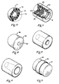
- Figures 4 and 5 illustrate closed cell elastomeric tube cleaners in a cubic and spherical configuration respectively.
- Figure 5 is partially broken away to illustrate interior structure.
- These tube cleaners may be made of rubber.
- the elastomer is of the closed cell type. This is to be constrasted with open cell sponge rubber. Further, for more severe cleaning requirements, as illustraed in Figure 5, carbon black or other abrasive may be dispersed throughout the tube cleaner.
- the tube cleaner may be cubic, as shown in Figure 4. It has been found that in multiple recirculations of a tube cleaner 2, points of the cube will be deformed to permit passage of a cubical tube cleaner through a heat exchanger tube. One edge of the cube is selected to be slightly larger than the inner diameter of a tube 3. Manufacture of cubical tube cleaners 2 is simplified and less expensive compared to manufacture of the traditional spherical tube cleaners, as shown in Figure 5 in cross-sectional form.
- Figure 6 is illustrative of a tube cleaner 2 in a cubical configuration incorporating flotation members 60, which may be, for example, polyurethane foam and an abrasive or cleaning member 62 comprising the remainder of the tube cleaner.
- a hollow tube could also be provided.
- Figure 8 illustrates another non-traditional shape for a tube cleaner, namely, a cylinder.
- elastomer is formed as a right circular cylinder. Again, the diameter of the right circular cylinder is selected to be slightly larger than the tube 3. The cylinders will tend to orient themselves within the inlet distribution head 12 at the point of entry to the tubes 3 for proper transport through the tubes.
- Figure 8a comprises a cylindrical flotation member 60 having a smaller diameter than the cylinder of Figure 8 and having cleaning members 62 mounted thereon. Cleaning members here and below may comprise medium durometer elastomer.
- Figure 9 is illustrative of a hollow spherical tube cleaner.
- the elastomeric material may comprise the closed cell, compressible material for providing variable buoyancy.
- the sphere itself may be compressed as a unit as opposed to collective compression of the individual closed cells therein.
- Figures 10 and 11 illustrate tube cleaners 2 having alternative methods to respond to increases in pressure to decrease the buoyancy thereof, namely provision for limited variable buoyancy.
- the tube cleaner 2 comprises a hollow, spherical body 70 having ports 71 communicating with an interior of the body 70.
- the ports 71 permit transmission of pressure from the exterior of the sphere 70 to the interior thereof.
- Mounted within the interior of the body 70 is a membrane 72 surrounding a core 73.
- the compressible fluid may comprise inert gas or condensible gas.
- the membrane 72 expands to a first diameter dependent on the size of the membrane itself and positively limited by the inner diameter of the hollow sphere 70.
- the diameter of the membrane 72 decreases.
- the maximum contraction is limited by the volume of the core 73.
- the core 73 must be porous so as to permit compression of the gas housed within the membrane 72 into the core 73.
- a limit on the compression of the membrane 72 is provided.
- a form of tube cleaner 2 is provided having limited variable buoyancy. Buoyancy of the tube cleaner 2 in this embodiment decreases as pressure thereon increases until the membrane 72 is compressed to the size of the core 73. Thereafter, increase in pressure does not decrease buoyancy.
- the tube cleaner 2 of the present embodiment can be constructed such that the tube cleaner 2 will have neutral buoyancy at any pressure over a selected threshold pressure, which threshold pressure can be one expected to be encountered in the inlet distribution head 12 to the heat exchanger 1.
- FIG. 11 is an isometric view of a right circular cylinder embodiment, partially broken away.
- a right circular cylinder 80 is provided having a port 81 communicating pressure to a piston 82 housed therein defining an enclosed portion 83 enclosing a compressible fluid as in the embodiment of Figure 10.
- a stop means 84 may be provided to limit travel of the piston 82 and compression of the fluid in the portion 83. Once again, a maximum density is provided for irrespective of pressure over a selected threshold level.
- FIG 12 is an isometric illustration of an embodiment in which a compressible flotation mem ber 88 and a relatively incompressible cleaning member 89 affixed thereto by fastening means 90 is provided.
- the flotation member 88 is shaped to fit for travel through a tube 3.
- the flotation member 88 comprises a truncated spheriod having the annular member 89 mating to the truncated portion thereof.
- the fastening means 90 extends through the center of the cleaning member 89 into the flotation member 88 along a diameter thereof. Edges of the outer diameter of either annulus 89 may be rounded. Alternatively, they may be initially left square for ease in manufacture and will be rounded upon progressing through repeated passes through the heat exchanger tubes 3.
- Figures 13 and 14 disclose alternative embodiments of the embodiment of Figure 8 in which a central opening is provided which decreases differential pressure across each cleaning element 2.
- the central opening may comprise a right circular cylinder, truncated cone or other convenient shape.
- Figure 15 further illustrates a central body 60 surrounded by an abrasive annular member 62.
- FIGs 16 and 17 represent a special case of the above embodiments in which the range of variability of buoyancy in response to pressure is zero.
- a flotation member 88 is provided which is substantially incompressible under expected pressures.
- the flotation member 88 and cleaning member 89 are proportioned to provide for neutral buoyancy.
- the cleaning member 89 is of an elastomer of high abrasion resistance and high flex failure resistance, e.g. polyurethane.
- the flotation member 88 may be bifurcated to abut opposite surfaces of the cleaning member 89 which is mounted in a plane on a diameter of the member 88, e.g.
- the flotation member 88 may have a groove formed in its circumference.
- the cleaning member 89 may be stretched over the flotation member 88 and snap into place in the groove.
- the cleaning member 89 is supported in the flotation member 88 and has only an annular peripheral portion projecting in a radial direction from the spheriod defined by the flotation member 88.
- the flotation member 88 is a sphere, and the cleaning member 89 is a deformable disc attached to and depending from the flotation member 88.
- the disc comprising the cleaning member 88 is deformable to form a convex surface in the direction of travel.
- Both embodiments are oriented in each tube 3 by hydraulic forces.
- Fastening means 92 maintain the members 88 and 89 in engagement.
- the fastening means 92 is engaged to the flotation member 88 sufficiently tightly to initiate the above-described cup-like deformation of the disc i.e., the cleaning member 89.
- the fastening means 92 need not be a screw; it could comprise a molded retaining means integral with the flotation member 88.
- the flotation member 88 has a longest dimension less than an inside diameter of a tube 3 through which it is intended to travel and the cleaning member 89 has a greater diameter.
- the cleaning member 89 is sufficiently elastomeric such that a side 91 seals thereof the inside diameter of a tube 3 and provides a wiping motion of its periphery against the inside diameter as the tube cleaner 2 moves in response to the pressure differential thereacross.
- the cleaning member 89 thus engages the tubes in a cleaning relationship.
- the side 91 may initially be squared and eventually become rounded due to wear.
- the diameter of the cleaning member 89 in the embodiment of Figure 16 is chosen so that the cleaning member 89 will be other than normal to an axis of a tube 3, illustrated as axis A in Figure 16, and will assume differing orientations in successive passes. Ideally, the tube cleaner 2 will rotate about the axis of the tube 3. In the embodiment of Figure 17, greater deformability of the cleaning member 89 is provided for, and the cleaning member 89 forms a cup upon entry into a tube 3. The material and the diameter of the cleaning member 89 are selected so that the cup "wobbles" in its travel through the tube 3 so that cleaning action is enhanced.
- Figure 18 is a mechanical schematic illustration partially illustrating a further embodiment of the system as illustrated in Figure 1. Elements in Figure 18 corresponding to elements in Figure 1 are denoted by similar reference numerals with a prime notation.
- tube cleaners 2 are intercepted by skimmer means in a horizontal component of direction of flow from an outlet and directed to recirculating means.
- skimming is most commonly utilized in connection with removal from the top of a liquid body. Here, it is used to indicate removal from a vertical extreme portion, which in the embodiment of Figure 18 happens to be a lower vertical extremity, namely the bottom.
- Another form of skimming means for cleaner retrieval from the bottom of the flow could comprise a settling basin.
- the tube cleaner 2 utilized is an open cell tube cleaner.
- the open cell tube cleaner 2 may be of known tube cleaning material such as sponge rubber or other suitable operation. Suitable operation is that which permits operation in accordance with the details described below.
- an interface 20 is provided at the outlet 11 which, once again, may be either an open flume or a closed pipe.
- use of open cell tube cleaners 2 is contemplated.
- the tube cleaners 2 contain air upon entry into tubes 3. Air is expelled from tube cleaners 2 by reintroduction of water into the cellular construction thereof under the differential pressure thereacross. Upon exiting from the heat exchanger 1, the tube cleaners will sink. The direction of travel will be in a horizontal direction and along the bottom of the outlet 11.
- a separator section 25 is formed such that tube cleaners 2 will be positioned for being intercepted in the horizontal direction of flow by a barrier means and diverted to a conduit 30 in a recirculation system 6.
- a barrier means 25 may comprise a vertical wall extending from a lower portion of the outlet 11.
- An inclined section 25a may be provided for permitting tube cleaners 2 to sink below the level of the lower wall of the outlet 22 so that continuing in their horizontal direction of travel they will impact the vertical wall portion 25.
- the tube cleaners 2 travel to a dewatering tank 34.
- the tube cleaners 2 are delivered to an inclined screen 93 for directing the tube cleaners 2 to dewatering rollers 94.
- the screen 93 as illustrated in Figure 18, could be either a conical screen having the rollers 94 positioned immediately below a central, circular opening thereof.
- the screen 93 could comprise the V-shaped intersection of planar surfaces within the contour of the tank 34, and the rollers 94 may be elongated, extending along a maximum dimension parallel to a diameter of the tank 34.
- the tube cleaners 2 exit via the conduit 41 for pumping by the pump 43 to the return conduit 44 and injection into the inlet stream as in the embodiment of Figure 1.
- the porous tube cleaners 2 are partially dewatered, i.e., water is removed to a preselected degree upon passage through the rollers 94.
- the tube cleaners 2 are not completely saturated upon their entry into the inlet distribution head 12.
- the degree to which the tube cleaners 2 are dewatered by the rollers 94 will be determinative of its buoyancy upon entry into the inlet distribution head 12. As in the embodiment of Figure 1, a neutral buoyancy is desired. This is because, in the presence of anticipated turbulence, a more uniform distribution of the vertical positions of tube cleaners 2 upon entry into the tube bundle 3 is achieved.
- rollers 94a may be provided in place of rollers 94 as shown in Figure 19.
- Two counter-rotating rollers are provided wherein the distance between the two surfaces is variable.
- the diameter of each roller 94a varies with distance along its axis of rotation. Consequently, the degree of dewatering of tube cleaners 2 will vary with the axial position with respect to the rollers 94 at which the tube cleaners 2 passed therethrough. Consequently, tube cleaners 2 will enter the inlet distribution head 12 having a distribution of buoyancies. This will aid the vertical distribution of tube cleaners 2 prior to entry into the tubes 3 and yield a more even dispersion.
- a nominal heat exchanger 1 may be 20 feet in height. In the common, prior art embodiment, better cleaning is achieved in the lower tubes and poor or no cleaning is achieved in the upper tubes.
- the tube cleaners 2 may be selected to have a longest dimension which is less than the inside diameter of a tube in the bundle 3. In the case of the spherical tube cleaner 2, this longest dimension would be a diameter of tube cleaner.
- diameter is used to mean the longest dimension of a tube cleaner 2, whether or not it is spherical.
- the present invention further comprises the method of injecting tube cleaners 2 for recirculation, which tube cleaners 2 have diameters smaller than the inner diameters of tubes in the bundle 3.
- an embodiment of the pressent invention contemplates cleaning due to impact of tube cleaners 2 against inner surfaces. It is contem plated that turbulence will propel tube cleaners 2 against the surfaces of the tubes in the bundle 3.
- Tube cleaners 2 such as in the embodiment of Figure 5 may be provided of sufficient compressibility to have variable density in accordance with the above teachings while having sufficient hardness to achieve a cleaning effect.
- novel tube cleaners of variable density or of limited variable density novel neutral buoyancy tube cleaners
- novel recirculation systems for utilizing either open cell or closed cell variable density tube cleaners and a system and method of utilizing tube cleaners in a novel system.
Landscapes
- Engineering & Computer Science (AREA)
- Mechanical Engineering (AREA)
- Physics & Mathematics (AREA)
- Fluid Mechanics (AREA)
- Chemical & Material Sciences (AREA)
- Combustion & Propulsion (AREA)
- General Engineering & Computer Science (AREA)
- Cleaning In General (AREA)
Priority Applications (3)
| Application Number | Priority Date | Filing Date | Title |
|---|---|---|---|
| US06/554,765 US4569097A (en) | 1983-11-23 | 1983-11-23 | Tube cleaners |
| AT85307586T ATE70907T1 (de) | 1985-10-21 | 1985-10-21 | Reinigungskoerper zum reinigen der innenwand eines rohres. |
| DE8585307586T DE3585032D1 (de) | 1985-10-21 | 1985-10-21 | Reinigungskoerper zum reinigen der innenwand eines rohres. |
Applications Claiming Priority (1)
| Application Number | Priority Date | Filing Date | Title |
|---|---|---|---|
| US06/554,765 US4569097A (en) | 1983-11-23 | 1983-11-23 | Tube cleaners |
Publications (2)
| Publication Number | Publication Date |
|---|---|
| EP0220347A1 true EP0220347A1 (fr) | 1987-05-06 |
| EP0220347B1 EP0220347B1 (fr) | 1991-12-27 |
Family
ID=24214629
Family Applications (1)
| Application Number | Title | Priority Date | Filing Date |
|---|---|---|---|
| EP85307586A Expired EP0220347B1 (fr) | 1983-11-23 | 1985-10-21 | Dispositif de nettoyage de la paroi interieure d'un tube |
Country Status (3)
| Country | Link |
|---|---|
| EP (1) | EP0220347B1 (fr) |
| FR (1) | FR2589090A1 (fr) |
| GB (1) | GB2181810B (fr) |
Cited By (10)
| Publication number | Priority date | Publication date | Assignee | Title |
|---|---|---|---|---|
| FR2618698A1 (fr) * | 1987-08-01 | 1989-02-03 | Sagawa Shizuo | Procede de nettoyage des canalisations |
| EP0487488A3 (en) * | 1990-10-19 | 1993-01-27 | Industrieanlagen-Planungs- Und Handelsgesellschaft M.B.H. | Method, cleaning agent, cleaning bodies and use of a cleaning agent for the cleaning of workpieces |
| EP0767010A1 (fr) * | 1995-10-05 | 1997-04-09 | Ryobi Ltd. | Procédé et système pour le nettoyage d'un passage de liquide au moyen de pression négative |
| WO2012044249A1 (fr) * | 2010-10-01 | 2012-04-05 | Hvs Engineering Pte Ltd | Système de nettoyage |
| WO2013006873A1 (fr) * | 2011-07-12 | 2013-01-17 | Johannes Paul Ennemoser | Dispositif de nettoyage pour échangeur de chaleur disposé verticalement |
| WO2015057163A1 (fr) * | 2013-10-14 | 2015-04-23 | Hvs Engineering Pte Ltd | Procédé de nettoyage d'un échangeur thermique |
| US9670586B1 (en) | 2008-04-09 | 2017-06-06 | Fcet, Inc. | Solid oxide fuel cells, electrolyzers, and sensors, and methods of making and using the same |
| CN111495894A (zh) * | 2020-05-29 | 2020-08-07 | 信达科创(唐山)石油设备有限公司 | 一种管线内部清洗系统及其清洗方法 |
| EP4549039A1 (fr) * | 2023-10-30 | 2025-05-07 | Tetra Laval Holdings & Finance S.A. | Nettoyage d'un condenseur dans un système de traitement thermique d'aliments liquides |
| WO2025104725A3 (fr) * | 2023-11-13 | 2025-06-26 | Cet Enviro Global Ltd. | Système de nettoyage pour échangeurs de chaleur à faisceau tubulaire |
Families Citing this family (5)
| Publication number | Priority date | Publication date | Assignee | Title |
|---|---|---|---|---|
| GB2258284A (en) * | 1991-07-22 | 1993-02-03 | Shell Int Research | A pipeline pig or tool |
| DE102006020079A1 (de) * | 2006-04-29 | 2007-11-08 | Wolf, Peter, Dr. | Vorrichtung zur gleichzeitiger parallelen Reinigung von Rohrleitungen |
| DE102007032232A1 (de) * | 2007-07-11 | 2009-01-15 | Ratner, Friedrich, Dr.-Ing. | Die Schwammgummikugeln |
| BRPI0911680A2 (pt) * | 2008-04-10 | 2019-05-07 | C 3 Int Llc | "pig" e método para aplicação de tratamento profiláticos de superfície |
| DE102011114326A1 (de) | 2011-09-24 | 2013-03-28 | Peter Wolf | Molchbarer, zerlegbarer Endloswärmetauscher |
Citations (14)
| Publication number | Priority date | Publication date | Assignee | Title |
|---|---|---|---|---|
| BE525076A (fr) * | ||||
| US1886419A (en) * | 1929-02-09 | 1932-11-08 | Franklin Dev Company | Slug for cleaning condenser tubes |
| FR1289600A (fr) * | 1961-02-22 | 1962-04-06 | Procédé de désincrustation automatique, et notamment de détartrage, de tubes à l'aide de billes abrasives, et dispositif correspondant | |
| FR2125684A5 (fr) * | 1971-02-16 | 1972-09-29 | Edf | |
| US3870373A (en) * | 1974-04-15 | 1975-03-11 | Continental Oil Co | Underground coal slurry concentrating sump |
| DE2541902A1 (de) * | 1974-09-20 | 1976-04-01 | Hitachi Ltd | Rotationskollektor |
| US4068327A (en) * | 1976-09-30 | 1978-01-17 | Joseph Heinlein | Swimming pool surface debris skimmer and method |
| EP0009137A1 (fr) * | 1978-09-23 | 1980-04-02 | Josef Koller | Dispositif de séparation de corps de nettoyage frottés |
| US4208220A (en) * | 1978-05-15 | 1980-06-17 | The Research Corporation Of The University Of Hawaii | Method and apparatus for cleaning heat exchanger tubes mounted transversely to vertical flow of seawater |
| EP0053355A1 (fr) * | 1980-12-01 | 1982-06-09 | ALSTHOM-ATLANTIQUE Société anonyme dite: | Elément de nettoyage et installation de nettoyage mettant en oeuvre cet élément |
| FR2527326A1 (fr) * | 1982-05-14 | 1983-11-25 | Taprogge Gmbh | Corps de nettoyage pour le nettoyage interne de tubes d'echangeurs de chaleur a tubes et leur procede de fabrication |
| DE3233941A1 (de) * | 1982-09-13 | 1984-03-15 | GEA-Energie-Systemtechnik GmbH & Co, 4690 Herne | Elastischer reibkoerper fuer das abreinigen der innenwandungen von rohren |
| DE3316022C1 (de) * | 1983-03-17 | 1984-08-30 | Taprogge GmbH, 4000 Düsseldorf | Verfahren und Anordnung zur UEberwachung der Betriebsfaehigkeit einer Einrichtung fuer die Reinigung der Roehren einer Kraftwerkskondensatoranlage o.dgl. |
| DE3325472C1 (de) * | 1983-07-14 | 1984-12-20 | Taprogge GmbH, 4000 Düsseldorf | Vorrichtung zur Einspeisung von Reinigungskörpern |
Family Cites Families (10)
| Publication number | Priority date | Publication date | Assignee | Title |
|---|---|---|---|---|
| GB293032A (en) * | 1927-06-30 | 1928-11-29 | Jakob Adolf | Improvements in bodies for cleaning pipe or hose lines and the like |
| GB700833A (en) * | 1951-11-12 | 1953-12-09 | Joseph Taprogge | Improvements in or relating to the automatic cleaning of cooling-water and like tubes |
| US3011197A (en) * | 1957-07-18 | 1961-12-05 | Mobay Chemical Corp | Pipeline cleaning devices |
| US3276061A (en) * | 1965-05-05 | 1966-10-04 | Williamson Inc T | Pipeline apparatus |
| US3707442A (en) * | 1970-02-27 | 1972-12-26 | Hitachi Ltd | Multistaged flash evaporator and a method of operating the same with sponge ball descaling treatment |
| JPS5111253B2 (fr) * | 1972-03-24 | 1976-04-09 | ||
| JPS534567B2 (fr) * | 1973-05-28 | 1978-02-18 | ||
| US3946455A (en) * | 1974-05-15 | 1976-03-30 | Marvin Echols | Cleaning device for tubes |
| US3983895A (en) * | 1975-04-17 | 1976-10-05 | Marathon Oil Company | Pump station bypass system |
| US4351387A (en) * | 1980-07-08 | 1982-09-28 | Louis Milia | Sieve assembly for cleaning bodies and heat exchanger system including same |
-
1985
- 1985-10-21 GB GB8525897A patent/GB2181810B/en not_active Expired - Lifetime
- 1985-10-21 EP EP85307586A patent/EP0220347B1/fr not_active Expired
- 1985-10-28 FR FR8515955A patent/FR2589090A1/fr active Pending
Patent Citations (14)
| Publication number | Priority date | Publication date | Assignee | Title |
|---|---|---|---|---|
| BE525076A (fr) * | ||||
| US1886419A (en) * | 1929-02-09 | 1932-11-08 | Franklin Dev Company | Slug for cleaning condenser tubes |
| FR1289600A (fr) * | 1961-02-22 | 1962-04-06 | Procédé de désincrustation automatique, et notamment de détartrage, de tubes à l'aide de billes abrasives, et dispositif correspondant | |
| FR2125684A5 (fr) * | 1971-02-16 | 1972-09-29 | Edf | |
| US3870373A (en) * | 1974-04-15 | 1975-03-11 | Continental Oil Co | Underground coal slurry concentrating sump |
| DE2541902A1 (de) * | 1974-09-20 | 1976-04-01 | Hitachi Ltd | Rotationskollektor |
| US4068327A (en) * | 1976-09-30 | 1978-01-17 | Joseph Heinlein | Swimming pool surface debris skimmer and method |
| US4208220A (en) * | 1978-05-15 | 1980-06-17 | The Research Corporation Of The University Of Hawaii | Method and apparatus for cleaning heat exchanger tubes mounted transversely to vertical flow of seawater |
| EP0009137A1 (fr) * | 1978-09-23 | 1980-04-02 | Josef Koller | Dispositif de séparation de corps de nettoyage frottés |
| EP0053355A1 (fr) * | 1980-12-01 | 1982-06-09 | ALSTHOM-ATLANTIQUE Société anonyme dite: | Elément de nettoyage et installation de nettoyage mettant en oeuvre cet élément |
| FR2527326A1 (fr) * | 1982-05-14 | 1983-11-25 | Taprogge Gmbh | Corps de nettoyage pour le nettoyage interne de tubes d'echangeurs de chaleur a tubes et leur procede de fabrication |
| DE3233941A1 (de) * | 1982-09-13 | 1984-03-15 | GEA-Energie-Systemtechnik GmbH & Co, 4690 Herne | Elastischer reibkoerper fuer das abreinigen der innenwandungen von rohren |
| DE3316022C1 (de) * | 1983-03-17 | 1984-08-30 | Taprogge GmbH, 4000 Düsseldorf | Verfahren und Anordnung zur UEberwachung der Betriebsfaehigkeit einer Einrichtung fuer die Reinigung der Roehren einer Kraftwerkskondensatoranlage o.dgl. |
| DE3325472C1 (de) * | 1983-07-14 | 1984-12-20 | Taprogge GmbH, 4000 Düsseldorf | Vorrichtung zur Einspeisung von Reinigungskörpern |
Cited By (18)
| Publication number | Priority date | Publication date | Assignee | Title |
|---|---|---|---|---|
| FR2618698A1 (fr) * | 1987-08-01 | 1989-02-03 | Sagawa Shizuo | Procede de nettoyage des canalisations |
| GB2207972A (en) * | 1987-08-01 | 1989-02-15 | Shizuo Sagawa | Cleaning pigs |
| DE3803045A1 (de) * | 1987-08-01 | 1989-02-16 | Shizuo Sagawa | Verfahren zum reinigen des inneren einer rohrleitung |
| GB2207972B (en) * | 1987-08-01 | 1991-10-16 | Shizuo Sagawa | Pipe cleaning method |
| EP0487488A3 (en) * | 1990-10-19 | 1993-01-27 | Industrieanlagen-Planungs- Und Handelsgesellschaft M.B.H. | Method, cleaning agent, cleaning bodies and use of a cleaning agent for the cleaning of workpieces |
| EP0767010A1 (fr) * | 1995-10-05 | 1997-04-09 | Ryobi Ltd. | Procédé et système pour le nettoyage d'un passage de liquide au moyen de pression négative |
| US9670586B1 (en) | 2008-04-09 | 2017-06-06 | Fcet, Inc. | Solid oxide fuel cells, electrolyzers, and sensors, and methods of making and using the same |
| CN103189709A (zh) * | 2010-10-01 | 2013-07-03 | Hvs工程私人有限公司 | 清洁系统 |
| CN103189709B (zh) * | 2010-10-01 | 2015-06-03 | Hvs工程私人有限公司 | 清洁系统 |
| US9182183B2 (en) | 2010-10-01 | 2015-11-10 | Hvs Engineering Pte Ltd | Cleaning system |
| WO2012044249A1 (fr) * | 2010-10-01 | 2012-04-05 | Hvs Engineering Pte Ltd | Système de nettoyage |
| WO2013006873A1 (fr) * | 2011-07-12 | 2013-01-17 | Johannes Paul Ennemoser | Dispositif de nettoyage pour échangeur de chaleur disposé verticalement |
| WO2015057163A1 (fr) * | 2013-10-14 | 2015-04-23 | Hvs Engineering Pte Ltd | Procédé de nettoyage d'un échangeur thermique |
| US10030920B2 (en) | 2013-10-14 | 2018-07-24 | Hvs Engineering Pte Ltd | Method of cleaning a heat exchanger |
| CN111495894A (zh) * | 2020-05-29 | 2020-08-07 | 信达科创(唐山)石油设备有限公司 | 一种管线内部清洗系统及其清洗方法 |
| EP4549039A1 (fr) * | 2023-10-30 | 2025-05-07 | Tetra Laval Holdings & Finance S.A. | Nettoyage d'un condenseur dans un système de traitement thermique d'aliments liquides |
| WO2025093269A1 (fr) * | 2023-10-30 | 2025-05-08 | Tetra Laval Holdings & Finance S.A. | Nettoyage d'un condenseur dans un système de traitement thermique d'aliments liquides |
| WO2025104725A3 (fr) * | 2023-11-13 | 2025-06-26 | Cet Enviro Global Ltd. | Système de nettoyage pour échangeurs de chaleur à faisceau tubulaire |
Also Published As
| Publication number | Publication date |
|---|---|
| GB2181810B (en) | 1990-06-13 |
| GB2181810A (en) | 1987-04-29 |
| EP0220347B1 (fr) | 1991-12-27 |
| GB8525897D0 (en) | 1985-11-27 |
| FR2589090A1 (fr) | 1987-04-30 |
Similar Documents
| Publication | Publication Date | Title |
|---|---|---|
| US4569097A (en) | Tube cleaners | |
| EP0220347A1 (fr) | Dispositif de nettoyage de la paroi interieure d'un tube | |
| JP3620670B2 (ja) | 下水管作業用循環排水装置 | |
| US5647428A (en) | Recovery of tube cleaners | |
| WO2000004974A8 (fr) | Filtre autonettoyant perfectionne | |
| US7282155B2 (en) | Device and a method for filtering a fluid | |
| US20120055858A1 (en) | Tertiary wastewater filtration using inclined filter media and internal reverse flow backwashing of filter disks | |
| CN114877086A (zh) | 一种高温高压输送管路用锻钢截止阀 | |
| US3911068A (en) | Pool chlorination diffuser | |
| CN112999704A (zh) | 一种污水沉淀处理装置 | |
| US3737039A (en) | Method of filtering | |
| CN101125708A (zh) | 斜微孔曝气软管 | |
| CA1313525C (fr) | Systeme de nettoyage de tubes par circulation interne, elements nettoyeurs et methode connexe | |
| CN218320914U (zh) | 一种河道污染浮油分离装置 | |
| CN85108447A (zh) | 管件内径清洁系统,清洁料和清洁方法 | |
| US5110463A (en) | Slurry filter apparatus with means to direct slurry to filter face at an angle | |
| JPS62102096A (ja) | チユ−ブ内径清掃システム、チユ−ブクリ−ナ、および方法 | |
| CN220047747U (zh) | 一种蚯蚓粪基质溶液的湍流汲取振搅激荡装置 | |
| DE19913969C1 (de) | Verfahren und Vorrichtung zur Erhöhung der Entgasungsleistung in hydraulischen Systemen | |
| CN2239591Y (zh) | 气水分离器 | |
| US5593469A (en) | Exhaust gas scrubber | |
| WO1995013124A1 (fr) | Filtre a sable dynamique | |
| CN220047343U (zh) | Y型过滤器滤网 | |
| CN219238009U (zh) | 一种内浮盘储罐浮动出油装置 | |
| GB2066407A (en) | Pig-trap |
Legal Events
| Date | Code | Title | Description |
|---|---|---|---|
| PUAI | Public reference made under article 153(3) epc to a published international application that has entered the european phase |
Free format text: ORIGINAL CODE: 0009012 |
|
| AK | Designated contracting states |
Kind code of ref document: A1 Designated state(s): AT CH DE LI NL SE |
|
| 17P | Request for examination filed |
Effective date: 19871104 |
|
| 17Q | First examination report despatched |
Effective date: 19880527 |
|
| GRAA | (expected) grant |
Free format text: ORIGINAL CODE: 0009210 |
|
| AK | Designated contracting states |
Kind code of ref document: B1 Designated state(s): AT CH DE LI NL SE |
|
| PG25 | Lapsed in a contracting state [announced via postgrant information from national office to epo] |
Ref country code: SE Effective date: 19911227 Ref country code: NL Effective date: 19911227 Ref country code: LI Effective date: 19911227 Ref country code: CH Effective date: 19911227 Ref country code: AT Effective date: 19911227 |
|
| REF | Corresponds to: |
Ref document number: 70907 Country of ref document: AT Date of ref document: 19920115 Kind code of ref document: T |
|
| REF | Corresponds to: |
Ref document number: 3585032 Country of ref document: DE Date of ref document: 19920206 |
|
| REG | Reference to a national code |
Ref country code: CH Ref legal event code: PL |
|
| NLV1 | Nl: lapsed or annulled due to failure to fulfill the requirements of art. 29p and 29m of the patents act | ||
| PLBE | No opposition filed within time limit |
Free format text: ORIGINAL CODE: 0009261 |
|
| STAA | Information on the status of an ep patent application or granted ep patent |
Free format text: STATUS: NO OPPOSITION FILED WITHIN TIME LIMIT |
|
| 26N | No opposition filed | ||
| PGFP | Annual fee paid to national office [announced via postgrant information from national office to epo] |
Ref country code: DE Payment date: 19941021 Year of fee payment: 10 |
|
| PG25 | Lapsed in a contracting state [announced via postgrant information from national office to epo] |
Ref country code: DE Effective date: 19960702 |