EP0220594A2 - Dispositif de garage pour voitures - Google Patents
Dispositif de garage pour voitures Download PDFInfo
- Publication number
- EP0220594A2 EP0220594A2 EP86114188A EP86114188A EP0220594A2 EP 0220594 A2 EP0220594 A2 EP 0220594A2 EP 86114188 A EP86114188 A EP 86114188A EP 86114188 A EP86114188 A EP 86114188A EP 0220594 A2 EP0220594 A2 EP 0220594A2
- Authority
- EP
- European Patent Office
- Prior art keywords
- platform
- parking device
- scissor
- sliding frame
- platforms
- Prior art date
- Legal status (The legal status is an assumption and is not a legal conclusion. Google has not performed a legal analysis and makes no representation as to the accuracy of the status listed.)
- Granted
Links
- 239000000969 carrier Substances 0.000 claims description 2
- 238000006073 displacement reaction Methods 0.000 claims description 2
- 238000010276 construction Methods 0.000 description 2
- 230000000694 effects Effects 0.000 description 1
- 230000002349 favourable effect Effects 0.000 description 1
Images

Classifications
-
- E—FIXED CONSTRUCTIONS
- E04—BUILDING
- E04H—BUILDINGS OR LIKE STRUCTURES FOR PARTICULAR PURPOSES; SWIMMING OR SPLASH BATHS OR POOLS; MASTS; FENCING; TENTS OR CANOPIES, IN GENERAL
- E04H6/00—Buildings for parking cars, rolling-stock, aircraft, vessels or like vehicles, e.g. garages
- E04H6/08—Garages for many vehicles
- E04H6/12—Garages for many vehicles with mechanical means for shifting or lifting vehicles
- E04H6/18—Garages for many vehicles with mechanical means for shifting or lifting vehicles with means for transport in vertical direction only or independently in vertical and horizontal directions
- E04H6/188—Garages for many vehicles with mechanical means for shifting or lifting vehicles with means for transport in vertical direction only or independently in vertical and horizontal directions using only vertical transport means
Definitions
- the invention relates to a parking device for motor vehicles with several superimposed, interconnected platforms for the motor vehicles, each of which can be raised together with a lifting drive or lowered into a pit in order to connect one of the platforms to a common driveway, and a plurality of such platform combinations in one Row are arranged side by side.
- DE-OS 31 45 370 describes a parking device of the type specified above, wherein several platform combinations are arranged side by side in a row.
- the upper and lower platforms of such a platform combination are rigidly connected to one another and can be raised or lowered by means of hydraulically driven lifting cylinders which are arranged on the side of the platform combination.
- the platforms are guided by rails or similar means.
- the guide is designed such that an inclination movement for the platforms is obtained simultaneously with the lifting and lowering movement.
- each platform combination has its own lifting drive, which is formed, for example, by hydraulic lifting cylinders which extend between the platform combinations and the bottom of the pit in which the parking device is arranged. It is well known to generate the pressure medium for several platform combinations by means of a common unit, but the individual lifting drive is assigned to the platform combination in each case. It is also known to combine three platforms with one another, for example. All parking devices of the type described are particularly intended to be installed in underground garages.
- the lower platform which is lowered into a pit, usually serves as a parking space for people working in the building, while the upper platform is intended for the rapidly changing public traffic. This type of use means that the lifting device itself is very rarely used.
- the invention is based on a parking device of the type described in the introduction and proposes that only one lifting drive is provided for a plurality of platform combinations and the lifting drive in the space below the lower platform, which is laterally displaceable and can be assigned to a platform combination, at right angles to the approach direction and the pit floor is arranged.
- the invention proposes a single lifting drive for several platform combinations.
- This lifting drive can be assigned to the platform combination that is to be lifted. It is clear that in the invention not several or all platform combinations of a parking device can be lifted at the same time. However, this is not a disadvantage when it comes to the use of such parking devices, since the necessity is only very rarely given lifting multiple platform combinations at the same time.
- a space is to be provided under the lower platform and the pit floor which is sufficient for the lifting drive in the lowered state. It has been found that even small heights are sufficient here, so that the additional space required in the invention remains small.
- the invention not only saves the large number of lifting cylinders on the side of the platform combinations of previous designs. The space requirement of these lifting cylinders can also be saved in the invention. The invention therefore requires less space in the horizontal direction than known parking devices, as a result of which the additional space requirement in the vertical direction is compensated for.
- the invention can be applied to platform combinations which are displaceable on rails and to those which can be pivoted about joints or other guide means during movement. Whether the platforms are only raised or inclined during the lifting movement is of secondary importance for the invention.
- a particularly advantageous effect of the invention is that no security devices are required for the platforms.
- the platform combinations are only in the raised position when the linear actuator is under the platform combination and is assigned to it.
- the linear actuator can only be moved laterally when the platform combination is in the lowered position.
- DE-OS 32 12 822 describes a parking device of another design, in which a laterally displaceable lifting device is provided, which can be assigned to several platforms arranged one above the other.
- this design does not have any platforms which are connected to one another to form platform combinations in the sense of the invention and also works with lifting devices which act on the platforms which can be lifted from above.
- Such a construction has the consequence that the hoist is at least partially arranged in the drivable space and that special means must always be provided to connect the hoist to the platforms.
- a particularly favorable embodiment of the proposal according to the invention is obtained when the lifting drive is formed by a scissor arrangement which is supported on a sliding frame and which acts on the lower platform of the platform combination from below with the elements which can be raised.
- a scissor arrangement requires little space when folded, and results in a sufficient lifting height.
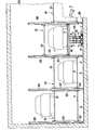
- a plurality of platform combinations 31 are arranged side by side in the underground garage 23.
- Each of the platform combinations consists of an upper platform 21 and a lower platform 4. Both platforms are connected to one another by struts 32.
- Each platform combination 31 is movable overall on the vertical guides 26. In the lowered state, each platform combination 31 rests on the supports 33, which are arranged at a height such that a space 2 remains under the lower platform 4 and the floor 3, which is sufficient to assign the lifting drive 1 to each of the platform combinations 31 in the folded state , ie to move laterally.
- each of the upper platforms 21 is in the lowered state at the level of the access 22 and can thus be driven on. Only when the platform combination 31 is raised by means of the lifting drive 1 can the respective lower platform be brought to the height of the access 22 as required.
- FIG. 2 shows a middle position, the one platform combination, the lower platform 4 of which accommodates a motor vehicle, being partially raised.
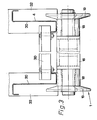
- the linear actuator 1 consists essentially of the sliding frame 5, which is laterally displaceable on the rails 28 by means of the rollers 27.
- the shift drive is not shown in detail.
- a motor can be mounted on the sliding frame, which drives the rollers 27.
- a stationary motor which is activated, for example, by a circulating rope.
- the displacement frame 5 carries a hydraulic pump unit 13 for driving the two hydraulic cylinders 11 of the scissors arrangement 34.
- the scissor assembly 34 consists essentially of the two scissor members 6 and 7, which are connected by the scissor joint 12.
- the lower end 8 of the link 6 is held on the sliding frame 5 by the joint 29, while the lower end 9 of the other scissor link 7 is movable in the guide 10. It is clear that when the cylinders 11 are acted upon, the scissors arrangement is erected and that the upper ends 14 and 15 will raise the respective platform combination 31.
- the upper ends 14 and 15 are provided with supports 16 and 17 which have a length which corresponds approximately to the width of the platforms 4. This makes it possible to make the scissors arrangement relatively narrow.
- the scissor arrangement does not have to be particularly stable against lateral forces, since the guides 26 guide the platform combinations sufficiently.
- the carriers 16 and 17 carry rollers 18 and flanges 19 at the ends.
- the rollers 18 support the support profiles of the platforms 4 from below and the flanges 19 provide sufficient lateral guidance. In spite of the large game, a sufficient mutual allocation is ensured.
- the support profiles 20 support the profiles 30 fastened thereon, which form the passable surface of the platforms 4. It is advantageous that the platforms 4 can have the same configuration as the upper platforms 21 with respect to the support profiles 20 and the profiles 30.
- this lifting drive 1 is moved under the platform combination to be lifted.
- the activated lifting drive raises the platform combination so that the lower platform 4 corresponds to the level of the access 22.
- the lifting drive is first lowered until the platform combination rests on the supports 33. As it further collapses, the lifting drive is released from the support profiles 20 and can be moved laterally on the rails 28 in space 2 in order to raise another platform combination.
- the scissor arrangement described is particularly suitable for those platform combinations in which the lower platform is only raised, but not inclined, during the lifting movement.
- the rollers 18 result in a total of four support points between the linear drive 1 and the platform combination.
- the arrangement can also be made such that the upper ends of the scissor members only engage the platform combination at one or two points if the platform combination has other suitable guides during the lifting movement. Such a construction is particularly suitable if the platform also executes an inclination movement during the lifting movement.
Landscapes
- Engineering & Computer Science (AREA)
- Architecture (AREA)
- Mechanical Engineering (AREA)
- Civil Engineering (AREA)
- Structural Engineering (AREA)
- Vehicle Cleaning, Maintenance, Repair, Refitting, And Outriggers (AREA)
- Warehouses Or Storage Devices (AREA)
- Vehicle Interior And Exterior Ornaments, Soundproofing, And Insulation (AREA)
- Auxiliary Methods And Devices For Loading And Unloading (AREA)
- Analysing Materials By The Use Of Radiation (AREA)
- Sampling And Sample Adjustment (AREA)
- Vehicle Step Arrangements And Article Storage (AREA)
- Electrical Discharge Machining, Electrochemical Machining, And Combined Machining (AREA)
Priority Applications (1)
| Application Number | Priority Date | Filing Date | Title |
|---|---|---|---|
| AT86114188T ATE76471T1 (de) | 1985-10-26 | 1986-10-14 | Parkvorrichtung fuer kraftfahrzeuge. |
Applications Claiming Priority (2)
| Application Number | Priority Date | Filing Date | Title |
|---|---|---|---|
| DE3538226 | 1985-10-26 | ||
| DE3538226A DE3538226C2 (de) | 1985-10-26 | 1985-10-26 | Parkvorrichtung für Kraftfahrzeuge |
Publications (3)
| Publication Number | Publication Date |
|---|---|
| EP0220594A2 true EP0220594A2 (fr) | 1987-05-06 |
| EP0220594A3 EP0220594A3 (en) | 1988-03-09 |
| EP0220594B1 EP0220594B1 (fr) | 1992-05-20 |
Family
ID=6284602
Family Applications (1)
| Application Number | Title | Priority Date | Filing Date |
|---|---|---|---|
| EP86114188A Expired - Lifetime EP0220594B1 (fr) | 1985-10-26 | 1986-10-14 | Dispositif de garage pour voitures |
Country Status (4)
| Country | Link |
|---|---|
| EP (1) | EP0220594B1 (fr) |
| JP (1) | JPH0733722B2 (fr) |
| AT (1) | ATE76471T1 (fr) |
| DE (2) | DE3538226C2 (fr) |
Cited By (2)
| Publication number | Priority date | Publication date | Assignee | Title |
|---|---|---|---|---|
| US7770695B2 (en) | 2007-08-22 | 2010-08-10 | Harding Steel, Inc. | Vehicle lift device including scissor lift and telescopic upper platform |
| CN112727180A (zh) * | 2020-12-29 | 2021-04-30 | 安徽春华智能科技有限公司 | 一种防摇摆的平面移动车库提升架 |
Families Citing this family (1)
| Publication number | Priority date | Publication date | Assignee | Title |
|---|---|---|---|---|
| CN114856274B (zh) * | 2022-03-11 | 2023-07-28 | 浙江镭蒙科技有限公司 | 一种立体车库用防坠落的固定举升机 |
Family Cites Families (8)
| Publication number | Priority date | Publication date | Assignee | Title |
|---|---|---|---|---|
| US1394999A (en) * | 1921-01-17 | 1921-10-25 | Frank Y Mckinstry | Overhead and underground storage for automobiles |
| DE1759343A1 (de) * | 1968-04-24 | 1971-06-16 | Kuester Hans Dieter | Garage fuer mehrere Kraftfahrzeuge |
| DE2415522C2 (de) * | 1974-03-30 | 1986-02-20 | Klaus, Kaspar, 8940 Memmingen | Garage zum Abstellen zweier Fahrzeuge übereinander |
| US4416578A (en) * | 1981-04-20 | 1983-11-22 | Behncke Hahns Juergen | Multi-story elevator-type garage |
| DE3145370A1 (de) * | 1981-11-14 | 1983-05-26 | Kaspar 8940 Memmingen Klaus | Vorrichtung fuer parkeinrichtungen |
| DE3212822C2 (de) * | 1982-04-06 | 1994-03-03 | Kaspar Klaus | Parkvorrichtung für Kraftfahrzeuge |
| JPS61242277A (ja) * | 1985-04-16 | 1986-10-28 | 日立造船株式会社 | 多列2段式駐車場 |
| DE3535682C2 (de) * | 1985-10-05 | 1993-11-18 | Kaspar Klaus | Parkvorrichtung für Kraftfahrzeuge |
-
1985
- 1985-10-26 DE DE3538226A patent/DE3538226C2/de not_active Expired - Fee Related
-
1986
- 1986-10-14 EP EP86114188A patent/EP0220594B1/fr not_active Expired - Lifetime
- 1986-10-14 AT AT86114188T patent/ATE76471T1/de not_active IP Right Cessation
- 1986-10-14 DE DE8686114188T patent/DE3685399D1/de not_active Expired - Lifetime
- 1986-10-21 JP JP61248557A patent/JPH0733722B2/ja not_active Expired - Lifetime
Cited By (3)
| Publication number | Priority date | Publication date | Assignee | Title |
|---|---|---|---|---|
| US7770695B2 (en) | 2007-08-22 | 2010-08-10 | Harding Steel, Inc. | Vehicle lift device including scissor lift and telescopic upper platform |
| CN112727180A (zh) * | 2020-12-29 | 2021-04-30 | 安徽春华智能科技有限公司 | 一种防摇摆的平面移动车库提升架 |
| CN112727180B (zh) * | 2020-12-29 | 2022-03-08 | 安徽春华智能科技有限公司 | 一种防摇摆的平面移动车库提升架 |
Also Published As
| Publication number | Publication date |
|---|---|
| DE3538226A1 (de) | 1987-04-30 |
| EP0220594A3 (en) | 1988-03-09 |
| ATE76471T1 (de) | 1992-06-15 |
| EP0220594B1 (fr) | 1992-05-20 |
| DE3538226C2 (de) | 1994-05-26 |
| DE3685399D1 (de) | 1992-06-25 |
| JPS62101761A (ja) | 1987-05-12 |
| JPH0733722B2 (ja) | 1995-04-12 |
Similar Documents
| Publication | Publication Date | Title |
|---|---|---|
| DE19723315C2 (de) | Durchlaßsperrvorrichtung | |
| EP3550095A1 (fr) | Système de stationnement | |
| DE3535682C2 (de) | Parkvorrichtung für Kraftfahrzeuge | |
| DE3212822C2 (de) | Parkvorrichtung für Kraftfahrzeuge | |
| DE2139743C2 (de) | Vorrichtung zum Parken mehrerer Fahrzeuge übereinander | |
| WO1992017668A1 (fr) | Parking a plusieurs etages | |
| DE3538226C2 (de) | Parkvorrichtung für Kraftfahrzeuge | |
| EP0731240B1 (fr) | Garage à plusieurs étages | |
| EP0456072B1 (fr) | Dispositif de parcage de véhicules automobiles sur des plates-formes | |
| EP1020591B1 (fr) | Système de garage | |
| DE4002665A1 (de) | Vertikale speichervorrichtung, insbesondere fuer kraftfahrzeuge | |
| DE2545074C3 (de) | Für Konzertsäle, Theater o.dgl. vorgesehene Tribüne mit mehreren höhenverstellbaren Plattformen | |
| EP0152789A2 (fr) | Dispositif pour garer des véhicules automobiles | |
| EP0979911A2 (fr) | Surface de sol ajustable en hauteur | |
| CH536919A (de) | Garage | |
| EP0060550B1 (fr) | Garage | |
| EP0353639A1 (fr) | Couverture de type volet roulant pour fosse de réparation et de montage | |
| DE1902556C3 (de) | Hebebühne für Kraftfahrzeuge, insbesondere für Personenwagen | |
| DE2913661A1 (de) | Abstellvorrichtung fuer kraftfahrzeuge | |
| EP0881343A1 (fr) | Appareil de parcage pour automobiles avec au moins deux places de parking superposées | |
| CH450288A (de) | Garage für Fahrzeuge, insbesondere Autos | |
| DE19905941A1 (de) | Parksystem | |
| DE29604213U1 (de) | Hebebühne | |
| DE2315417A1 (de) | Parkeinrichtung zum abstellen zweier fahrzeuge uebereinander | |
| DE2829791C2 (de) | Brunnenkopf |
Legal Events
| Date | Code | Title | Description |
|---|---|---|---|
| PUAI | Public reference made under article 153(3) epc to a published international application that has entered the european phase |
Free format text: ORIGINAL CODE: 0009012 |
|
| AK | Designated contracting states |
Kind code of ref document: A2 Designated state(s): AT CH DE GB IT LI |
|
| PUAL | Search report despatched |
Free format text: ORIGINAL CODE: 0009013 |
|
| AK | Designated contracting states |
Kind code of ref document: A3 Designated state(s): AT CH DE GB IT LI |
|
| 17P | Request for examination filed |
Effective date: 19880329 |
|
| 17Q | First examination report despatched |
Effective date: 19890425 |
|
| GRAA | (expected) grant |
Free format text: ORIGINAL CODE: 0009210 |
|
| AK | Designated contracting states |
Kind code of ref document: B1 Designated state(s): AT CH DE GB IT LI |
|
| REF | Corresponds to: |
Ref document number: 76471 Country of ref document: AT Date of ref document: 19920615 Kind code of ref document: T |
|
| ITF | It: translation for a ep patent filed | ||
| REF | Corresponds to: |
Ref document number: 3685399 Country of ref document: DE Date of ref document: 19920625 |
|
| GBT | Gb: translation of ep patent filed (gb section 77(6)(a)/1977) | ||
| PLBE | No opposition filed within time limit |
Free format text: ORIGINAL CODE: 0009261 |
|
| STAA | Information on the status of an ep patent application or granted ep patent |
Free format text: STATUS: NO OPPOSITION FILED WITHIN TIME LIMIT |
|
| 26N | No opposition filed | ||
| PGFP | Annual fee paid to national office [announced via postgrant information from national office to epo] |
Ref country code: AT Payment date: 19951013 Year of fee payment: 10 |
|
| PGFP | Annual fee paid to national office [announced via postgrant information from national office to epo] |
Ref country code: GB Payment date: 19951026 Year of fee payment: 10 |
|
| PGFP | Annual fee paid to national office [announced via postgrant information from national office to epo] |
Ref country code: CH Payment date: 19951124 Year of fee payment: 10 |
|
| PGFP | Annual fee paid to national office [announced via postgrant information from national office to epo] |
Ref country code: DE Payment date: 19951220 Year of fee payment: 10 |
|
| PG25 | Lapsed in a contracting state [announced via postgrant information from national office to epo] |
Ref country code: GB Effective date: 19961014 Ref country code: AT Effective date: 19961014 |
|
| PG25 | Lapsed in a contracting state [announced via postgrant information from national office to epo] |
Ref country code: LI Effective date: 19961031 Ref country code: CH Effective date: 19961031 |
|
| GBPC | Gb: european patent ceased through non-payment of renewal fee |
Effective date: 19961014 |
|
| REG | Reference to a national code |
Ref country code: CH Ref legal event code: PL |
|
| PG25 | Lapsed in a contracting state [announced via postgrant information from national office to epo] |
Ref country code: DE Effective date: 19970701 |
|
| PG25 | Lapsed in a contracting state [announced via postgrant information from national office to epo] |
Ref country code: IT Free format text: LAPSE BECAUSE OF NON-PAYMENT OF DUE FEES;WARNING: LAPSES OF ITALIAN PATENTS WITH EFFECTIVE DATE BEFORE 2007 MAY HAVE OCCURRED AT ANY TIME BEFORE 2007. THE CORRECT EFFECTIVE DATE MAY BE DIFFERENT FROM THE ONE RECORDED. Effective date: 20051014 |