EP0220627A2 - Véhicule de transport de chevaux, en particulier remorque - Google Patents
Véhicule de transport de chevaux, en particulier remorque Download PDFInfo
- Publication number
- EP0220627A2 EP0220627A2 EP86114400A EP86114400A EP0220627A2 EP 0220627 A2 EP0220627 A2 EP 0220627A2 EP 86114400 A EP86114400 A EP 86114400A EP 86114400 A EP86114400 A EP 86114400A EP 0220627 A2 EP0220627 A2 EP 0220627A2
- Authority
- EP
- European Patent Office
- Prior art keywords
- roof
- horse
- substructure
- wings
- drawn
- Prior art date
- Legal status (The legal status is an assumption and is not a legal conclusion. Google has not performed a legal analysis and makes no representation as to the accuracy of the status listed.)
- Withdrawn
Links
- 241000283086 Equidae Species 0.000 abstract description 8
- 101100498160 Mus musculus Dach1 gene Proteins 0.000 description 3
- 239000004033 plastic Substances 0.000 description 3
- 229910052782 aluminium Inorganic materials 0.000 description 2
- XAGFODPZIPBFFR-UHFFFAOYSA-N aluminium Chemical compound [Al] XAGFODPZIPBFFR-UHFFFAOYSA-N 0.000 description 2
- 230000006835 compression Effects 0.000 description 2
- 238000007906 compression Methods 0.000 description 2
- 229920001971 elastomer Polymers 0.000 description 2
- 230000001771 impaired effect Effects 0.000 description 2
- 229920000728 polyester Polymers 0.000 description 2
- 230000007704 transition Effects 0.000 description 2
- 229910000831 Steel Inorganic materials 0.000 description 1
- 239000006096 absorbing agent Substances 0.000 description 1
- 238000006243 chemical reaction Methods 0.000 description 1
- 238000004140 cleaning Methods 0.000 description 1
- 239000004744 fabric Substances 0.000 description 1
- 229920001821 foam rubber Polymers 0.000 description 1
- 230000005484 gravity Effects 0.000 description 1
- 229910052751 metal Inorganic materials 0.000 description 1
- 239000002184 metal Substances 0.000 description 1
- 230000002093 peripheral effect Effects 0.000 description 1
- 238000009420 retrofitting Methods 0.000 description 1
- 238000007789 sealing Methods 0.000 description 1
- 230000035939 shock Effects 0.000 description 1
- 239000007787 solid Substances 0.000 description 1
- 239000010959 steel Substances 0.000 description 1
- 230000001360 synchronised effect Effects 0.000 description 1
Images

Classifications
-
- B—PERFORMING OPERATIONS; TRANSPORTING
- B60—VEHICLES IN GENERAL
- B60P—VEHICLES ADAPTED FOR LOAD TRANSPORTATION OR TO TRANSPORT, TO CARRY, OR TO COMPRISE SPECIAL LOADS OR OBJECTS
- B60P3/00—Vehicles adapted to transport, to carry or to comprise special loads or objects
- B60P3/04—Vehicles adapted to transport, to carry or to comprise special loads or objects for transporting animals
Definitions
- the invention relates to a horse-drawn wagon, in particular trailer, with a trough-like, on a chassis mounted substructure, on the rear of which a door serving for entry and exit is provided and with a roof supported by the substructure.
- Horses are mostly transported on the road in horse-drawn trailers, with a passenger car serving as the towing vehicle in the majority of cases. Sometimes self-propelled horse transport vehicles are in use, but their use is more limited to the professional area.
- the invention relates primarily to road transport vehicles of this type without being restricted to this application.
- the term “horse transport wagon” is also understood to mean any type of transport box which is suitable for other means of transport, in particular for airplanes.
- Horses can often only be moved with great difficulty through the door into the interior of a horse transporter, many horses shy away from or when entering the darker interior of the horse transporter, which is closed in their direction of view. They are often only after a long time and with a lot of effort to get them into the To enter the dolly. The reason for this is, in particular, that the horse-drawn wagon should not exceed a certain height for traffic-related reasons.
- a high altitude also means a large surface for wind, for example cross winds.
- the roof in a horse-drawn wagon is much lower than, for example, in a box.
- transport wagons which not only have a door on their rear surface, like the horse transport wagon of the type mentioned, but are also equipped with a door on their front surface.
- This front door is opened when the horse is to get into the trolley and is closed as soon as the horse is in the trolley.
- a chest bar is provided so that the horse does not exit through the front door.
- this object is achieved by a lifting device arranged between the substructure and the roof for lifting the roof relative to the substructure.
- the roof can be lifted from a normal closed position to a raised position in which there is a space between the roof and the substructure.
- the horse By lifting the roof off the substructure, the horse has a clear view to the front and to the side when getting into the trolley, so that it does not initially recognize the narrowness of the trolley.
- the roof is in the raised position at a height that corresponds, for example, to the roof height in a horse box. Overall, it is achieved that sensitive horses can be moved much easier to get into the transport trolley than was the case with other, especially small (eg transport trolleys for two horses).
- the design of the lifting device is basically arbitrary, scissor systems, lifting systems with a rack or spindle or the like are suitable.
- the training is designed as a parallelogram system.
- This system has the particular advantages that, on the one hand, the movements of the lifting systems of the left and right sides can be synchronized with little effort, for example by connecting the front rockers to one another, while the available interior of the horse transport vehicle is left unchanged.
- the lifting device can be designed so that the roof lifts more in the front area than in the rear area, that is to say an inclined position is reached in the raised position. For the horse, this has the advantage that the view upwards is released to an improved degree.
- the lifting device is particularly suitable for horse transport vehicles with a single-shell plastic roof, for example made of polyester. Such roof shells are relatively dimensionally stable and therefore only require a small number of fixation points for the substructure.
- the lifting device can also be attached to other horse transport vehicles, for example with a fabric roof that is stiffened by a metal or plastic frame.
- the special advantage of the lifting device is that it can be operated practically in seconds and with little effort, the operation can be carried out from a conveniently accessible location.
- a largely rigid U-shaped bracket with its legs forms the front wings of a parallelogram, it is attached to the left and right side walls of the substructure in the region of the transition from its legs to the base steers, the hinge points are as far as possible in the front area of the substructure.
- the parallelogram is completed by two rear wings, which are shorter in their effective length than the one-piece front wings. The front wings attack approximately below the center of gravity of the roof, so that the rear, separate wings serve essentially only for guidance.
- the lifting device is assigned a telescopic tube with an energy store, for example compressed air or a coil spring.
- an energy store for example compressed air or a coil spring.
- the spreading force is such that the roof can be lifted and closed essentially without force. Only mechanical losses, friction losses and the like can then be overcome during operation.
- the lifting device can thus be constructed relatively simply; it is also suitable for retrofitting in existing transport trolleys. It can also be optically integrated into the overall picture of the transport vehicle. It can be carried out absolutely maintenance-free. When opening and closing there are no noises that could scare a horse.
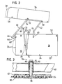
- the horse transport trailer shown in perspective in FIG. 1 has a trough-like substructure 22 which is mounted on a two-axle chassis 20 and which is constructed from a floor, a left side wall 24, a front wall 26 and a rear wall.
- a type of door - not shown in the figures - is provided, through which a horse can enter and exit the interior of the horse transport trailer.
- the side wall 24 consists of a longer rear side wall part 28 running in the direction of travel and a shorter front side wall part 30 which is inclined to the direction of travel and in which a small door 32 is provided. Except for this door 32, the horse transport trailer is folded symmetrically in the longitudinal direction.
- a trough-shaped roof 34 is attached to the closed peripheral upper edge of the substructure 22, which closes the substructure 22 in a rainproof manner at the top.
- the roof is unchanged compared to the previously known horse-drawn wagon, so that the design of the roof is not detailed must be gone.
- the roof is preferably a plastic shell, in particular a polyester shell, which is appropriately reinforced. Overall, the bowl-shaped roof 34 has a high inherent rigidity due to its trough shape.
- the front front wall 26 is flat, it is vertical and extends 90 ° to the direction of travel. In the case of other horse transport trailers, this front wall 26 is embodied in an arc shape, it nestles tangentially into the oblique course of the front side wall part 30. This also does not merge into the rear side wall part 28 in a kink, but into this in a curve. 2, the front edge has the reference number 36. The roof in its front area is matched to the curved shape of the front wall 26, this is indicated by the roof front edge 38 in FIG. 2.
- a lifting device is arranged between the substructure 22 and the roof 34, which is explained in more detail below:
- the roof 24 is articulated on the substructure 22 on both sides of the substructure 22 via a front rocker arm 40 and a rear rocker arm 42.
- the front rockers 40 on both sides are rigid and, as in the exemplary embodiment shown, are preferably connected to one another in one piece.
- the front rockers 40 each form the legs of a U-shaped bracket, the base 44 of which runs parallel to the front wall 26.
- each front rocker 40 or each leg of the U-bracket initially runs parallel to the associated oblique side wall part 24, that is to say diverging and then, in the area of the transition between the front side wall part 30 and the rear side wall part 28 parallel to the rear side wall part 28, in this area the corresponding parts of the front wings on both sides run parallel to one another.
- the front rockers 40 are not carried directly, but rather are supported by a short, vertically downward-pointing arm 46 on the substructure 26 in a joint 48.
- the location of this joint 48 should be as far forward as possible, from FIGS. 1 and 2 it can be seen that the joint is practically at the level of the flat front wall 26.
- the hinge 48 continues to lie around the length of the arm 46 below the upper edge 50 of the substructure 22.
- the connection area of the front rockers 40 with their respective arm 46 is approximately the same distance from the base 44 of the U-bracket as from the hinge 48. Due to the arrangement of the joint 48 at the lower end of the arm 46, the base 44 of the U-bracket maintains a sufficient distance from the front wall 26 when the front rockers 40 are pivoted up, as shown in FIG. 2.
- This has particular advantages for the horse transport trailer described above with a curved front wall 26, that is to say the front edge 36 shown in dashed lines. As FIG. 2 shows, there is also sufficient clearance between the front edge 36 and the base 44 of the U-bracket in this embodiment.
- an arm 46 could be dispensed with entirely and the joint 48 could be arranged directly on the front rocker 40 and, for example, in the current connection area of this front rocker 40 with the arm 46.
- the front rockers 40 are provided with a bevel 52, which will be discussed later, and in one area in the vicinity of this bevel 52 Joint 54 articulated on the roof 34.
- the hinge point 54 is located very close to the lower edge 56 of the roof 34 and approximately perpendicularly below the center of mass of the roof 34.
- the effective length of the two (equally long) front rockers 40, that is to say the distance between the hinge points 48, 54 corresponds approximately to the height of the substructure 22 .
- the effective length of the two rear wings, which are also of equal length, on both sides is approximately only 85 to 90 percent of the effective length of the front wings 40 mentioned, as a result of which the four-bar linkage forming the lifting device deviates slightly from a true parallelogram.
- the rear rockers 42 are connected (on both sides) to the roof 34 in a joint 58 and are carried in their other end region in a joint 60 on the substructure 22, specifically on the rear side wall part 28.
- the articulation points 48, 54, 58 and 60 form the described quadrilateral.
- the hinge point 60 is located slightly in front of half the total length of the substructure 22 and at the same height as the hinge 48 , 58 extends laterally. When the roof 34 is completely closed, it is practically completely covered by the wings 40, 42 in the side perspective.
- the rear rockers 42 have an angled portion 64 of approximately 30 ° in their lower third. As a result, its upper region runs practically parallel to the front rockers 40 in the raised position shown in FIG. 2, while the lower region runs almost vertically. Through the bend 64 it is achieved that the longer upper region in the closed position of the roof 34 (see FIG. 1) is parallel to edges 50, 56 and thus to the parting plane of roof 34 and substructure 22. The bevel 52 then runs parallel to the lower section of the rear rocker 42, leaving only a small gap. Visually, this gives the impression in the closed position that the upper parts of the rear wings 42 extend the front wings 40. As shown in FIG. 1, the U-bracket forming the front wings 40 also lies in the closed position above the parting plane between the roof 34 and Substructure 22 and covers the edges 50, 56.
- the roof 34 is strapped to the substructure 22 via a number of turnbuckles 66, for example four pieces.
- Other fasteners such as. B. the rubber pull tabs known from older motor vehicles are possible.
- a second arm 68 is attached to the front rocker 40 there in the vicinity of its angled portion, but in the region of the rear side wall part 28 running in the direction of travel, which, like the first arms, extends for a distance of approximately Protrudes 18 cm downwards at right angles.
- a joint 70 At its lower, free end, it is articulated in a joint 70 to a telescopic rod 72, which is carried in a joint 74 at its lower end region at the level of the base of the substructure 22 in the foremost, lowermost corner region of the front left side wall part 30.
- this telescopic rod 72 In the normal closed position, this telescopic rod 72 is vertical, at the same time the articulation points 48, 60 and 70 are at the same height.
- the telescopic rod 72 is constructed from two concentric tubes, an outer tube 76 and an inner tube 78, which are guided into one another and are biased towards one another in the pull-out direction by an internal helical compression spring (not shown).
- a clamping lever 80 is provided, as is also known for the extension of handles of window cleaning devices. It enables the outer tube 76 to be frictionally locked to the inner tube 78 in any position between the normal closed position and the maximum open position.
- a form-fitting locking device can also be used, for this purpose impressions must be provided at a certain distance in the inner tube 78, into which a locking part of the locking device can engage in a spring-loaded manner.
- Other training courses are possible.
- the described, relatively long helical compression spring accommodated in the telescopic rod 72 is dimensioned in terms of force such that it absorbs the weight of the entire roof including the proportionate weights of the movable parts of the lifting device. It is preferably even set a little more strongly than the stated value.
- any intermediate positions can be inserted between the maximum open position and the closed position be taken.
- This has the advantage, for example, that the roof 34 can be raised slightly when the horse transport trailer is not being moved and a horse is in it. This gives the horse fresh air.
- the telescopic rod 72 described is merely an exemplary embodiment for an advantageous (but not absolutely necessary) weight compensation of the horn device.
- a gas pressure spring, an oil pressure shock absorber with an energy store or the like can also be used.
- the location of the telescopic rod 72 is also basically arbitrary, for example a tension spring can also be arranged parallel to the front wall 26 between the base 44 and a lower region of the front wall 26.
- a joint 54 is explained in FIG. 3; the joints 58 are also designed analogously.
- the interior of the horse-drawn wagon is shown in Figure 3 below.
- a very flat inner stiffening strip 82 is provided, which essentially serves as a tear-proof hold for fastening means of the roof 34.
- these fastening means are designed as countersunk screws.
- the stiffening strip 62 already described, so that both stiffening strips 62, 82 clamp the roof 34 between them.
- the joint 48 itself is constructed as follows: a screw 84 engages through a hole in the stiffening strip 62, a nut 86 is screwed onto the inside of the roof 34. The screw tensions a sleeve 88 which pulls it against the stiffening strip 62. A bearing bush 90 is inserted (welded) into the front rocker 40, and a bearing braid is provided between it and the sleeve 88 in order to make the articulation points completely maintenance-free.
- the U-bracket forming the two front rockers 40 and the two rear rockers 42 are made of stable square tube made of aluminum or steel, for example an aluminum tube 40 x 60 x 2.5.
- an elastic rubber seal for example a lip seal known from the automotive field or a foam rubber seal, can be provided in order to improve the seal between the roof 34 and the substructure.
- the front edge of the roof 34 is located in front of the front wall 26.
- the roof 34 has a free space of approximately 80 cm.
Landscapes
- Engineering & Computer Science (AREA)
- Health & Medical Sciences (AREA)
- Public Health (AREA)
- Transportation (AREA)
- Mechanical Engineering (AREA)
- Fittings On The Vehicle Exterior For Carrying Loads, And Devices For Holding Or Mounting Articles (AREA)
- Body Structure For Vehicles (AREA)
- Handcart (AREA)
Applications Claiming Priority (2)
| Application Number | Priority Date | Filing Date | Title |
|---|---|---|---|
| DE3538196 | 1985-10-26 | ||
| DE19853538196 DE3538196A1 (de) | 1985-10-26 | 1985-10-26 | Pferdetransportwagen, insbesondere -anhaenger |
Publications (2)
| Publication Number | Publication Date |
|---|---|
| EP0220627A2 true EP0220627A2 (fr) | 1987-05-06 |
| EP0220627A3 EP0220627A3 (fr) | 1989-03-29 |
Family
ID=6284584
Family Applications (1)
| Application Number | Title | Priority Date | Filing Date |
|---|---|---|---|
| EP86114400A Withdrawn EP0220627A3 (fr) | 1985-10-26 | 1986-10-17 | Véhicule de transport de chevaux, en particulier remorque |
Country Status (3)
| Country | Link |
|---|---|
| US (1) | US4732419A (fr) |
| EP (1) | EP0220627A3 (fr) |
| DE (1) | DE3538196A1 (fr) |
Cited By (1)
| Publication number | Priority date | Publication date | Assignee | Title |
|---|---|---|---|---|
| FR2725682A1 (fr) * | 1994-10-17 | 1996-04-19 | Attard Jean Yves | Remorque perfectionnee |
Families Citing this family (6)
| Publication number | Priority date | Publication date | Assignee | Title |
|---|---|---|---|---|
| NZ246515A (en) * | 1992-01-07 | 1996-07-26 | Dualmist Pty Ltd Substituted F | Animal transporter; upper portions of side walls constrain sideways movement of animals upper body and the lower wall portions diverge from side wall upper portions |
| DE10052437B4 (de) * | 2000-10-23 | 2009-06-18 | Bpw Bergische Achsen Kg | Verstellbare Verstrebung |
| US6755155B2 (en) * | 2002-06-24 | 2004-06-29 | Nancy May | Horse trailer |
| GB0221128D0 (en) * | 2002-09-12 | 2002-10-23 | Francis Robert | Trailers |
| US7124711B1 (en) * | 2004-12-02 | 2006-10-24 | Bearden Paul D | Gate closing apparatus |
| US20080073937A1 (en) * | 2006-09-25 | 2008-03-27 | Loran A. Circle | Trailer with access hatch |
Family Cites Families (8)
| Publication number | Priority date | Publication date | Assignee | Title |
|---|---|---|---|---|
| GB474864A (en) * | 1936-12-02 | 1937-11-09 | J H Jennings & Son Ltd | Improvements in vehicles for the road transport of horses and other animals |
| US2531140A (en) * | 1948-02-13 | 1950-11-21 | Chance Co Ab | Trailer vehicle for hot line tools |
| US2963313A (en) * | 1959-05-22 | 1960-12-06 | James H Bennett | Travel trailer |
| US3053224A (en) * | 1960-04-19 | 1962-09-11 | Hartman Trailer Mfg Company In | Horse trailer |
| FR1479272A (fr) * | 1965-12-21 | 1967-05-05 | Remorque pour le transport routier d'un cheval | |
| CA1005096A (en) * | 1974-02-27 | 1977-02-08 | Michael Gogush | Elevating mechanism for the roofs or tops of vans and the like |
| DE7933410U1 (de) * | 1979-11-27 | 1980-06-04 | Arau, Jaime, Dipl.-Ing., 7054 Korb | Geschlossener Fahrzeug-Transportanhänger |
| US4613181A (en) * | 1985-11-25 | 1986-09-23 | Rafi Zadeh Hassan | Cover assembly for pickup truck bed |
-
1985
- 1985-10-26 DE DE19853538196 patent/DE3538196A1/de not_active Withdrawn
-
1986
- 1986-10-17 EP EP86114400A patent/EP0220627A3/fr not_active Withdrawn
- 1986-10-24 US US06/922,854 patent/US4732419A/en not_active Expired - Fee Related
Cited By (1)
| Publication number | Priority date | Publication date | Assignee | Title |
|---|---|---|---|---|
| FR2725682A1 (fr) * | 1994-10-17 | 1996-04-19 | Attard Jean Yves | Remorque perfectionnee |
Also Published As
| Publication number | Publication date |
|---|---|
| US4732419A (en) | 1988-03-22 |
| DE3538196A1 (de) | 1987-04-30 |
| EP0220627A3 (fr) | 1989-03-29 |
Similar Documents
| Publication | Publication Date | Title |
|---|---|---|
| DE2018319C3 (de) | HeckabschluB für die Laderaumöffnung eines Kombiwagens | |
| DE19513520C1 (de) | Kraftfahrzeug mit einer Heckklappe, insbesondere für Mehrzweck- oder Kombiwagen | |
| DE2624296A1 (de) | Schiebetuer fuer fahrzeuge, insbesondere kraftfahrzeuge | |
| DE3200792A1 (de) | "fahrzeug-anhaenger" | |
| DE68909281T2 (de) | Verstellbare Säule für ein Lastkraftfahrzeug mit verschiebbarer Abdeckung. | |
| DE102019107788A1 (de) | Öffnungsfähiger Aufbau für einen Unterbau | |
| DE19731324A1 (de) | Ausziehbarer Ladeboden für ein Fahrzeug | |
| DE4011315A1 (de) | Haltevorrichtung fuer fahrzeug-hecklasten | |
| CH670224A5 (fr) | ||
| DE69010656T2 (de) | Ausstellbare Hauben für Eisenbahnwagen. | |
| DE3531394A1 (de) | Wohnmobil mit ausziehbarer verlaengerungskoje | |
| EP0220627A2 (fr) | Véhicule de transport de chevaux, en particulier remorque | |
| DE3837252A1 (de) | Kraftfahrzeug, insbesondere personenkraftwagen, mit in seiner laenge veraenderbarem heckteil | |
| DE2710141A1 (de) | Aufbau fuer einen lastkraftwagen oder anhaenger mit ladebordwaenden | |
| DE102010045356A1 (de) | Lastenträger mit einem Schwenkschiebelager | |
| AT394832B (de) | Kastenartiger aufbau fuer ein lastfahrzeug | |
| DE1803913C2 (de) | Vorrichtung zum Öffnen und Schließen einer Seilbahnkabine | |
| DE69807589T2 (de) | Vertikal bewegbare Plattform mit Geländer, zur Montage auf einem Fahrzeug | |
| DE8816910U1 (de) | Einsatzfahrzeug, insbesondere Feuerwehrfahrzeug, mit einer Ausrüstungskabine | |
| DE3437848A1 (de) | Anhaenger mit kabine | |
| EP0825050A1 (fr) | Rancher entre une membrure supérieure et le châssis d'un véhicule | |
| DE4201215C1 (fr) | ||
| CH656917A5 (de) | Trag- und fuehrungsvorrichtung fuer eine schiebewand. | |
| DE1804953C3 (de) | Mehrstufiger, im Fahrzeugprofil befindlicher Einstieg für Fahrzeuge, insbesondere Schienenfahrzeuge | |
| DE3302620C2 (fr) |
Legal Events
| Date | Code | Title | Description |
|---|---|---|---|
| PUAI | Public reference made under article 153(3) epc to a published international application that has entered the european phase |
Free format text: ORIGINAL CODE: 0009012 |
|
| AK | Designated contracting states |
Kind code of ref document: A2 Designated state(s): AT BE CH DE ES FR GB IT LI LU NL SE |
|
| PUAL | Search report despatched |
Free format text: ORIGINAL CODE: 0009013 |
|
| AK | Designated contracting states |
Kind code of ref document: A3 Designated state(s): AT BE CH DE ES FR GB IT LI LU NL SE |
|
| STAA | Information on the status of an ep patent application or granted ep patent |
Free format text: STATUS: THE APPLICATION IS DEEMED TO BE WITHDRAWN |
|
| 18D | Application deemed to be withdrawn |
Effective date: 19890930 |
|
| RIN1 | Information on inventor provided before grant (corrected) |
Inventor name: KETTERER, MICHAEL Inventor name: MEROTH, ERWIN |