EP0220769B1 - Verfahren zur Herstellung einer bei hoher Temperatur verwendbaren Feder vom zylindrischen Typ - Google Patents
Verfahren zur Herstellung einer bei hoher Temperatur verwendbaren Feder vom zylindrischen Typ Download PDFInfo
- Publication number
- EP0220769B1 EP0220769B1 EP86201815A EP86201815A EP0220769B1 EP 0220769 B1 EP0220769 B1 EP 0220769B1 EP 86201815 A EP86201815 A EP 86201815A EP 86201815 A EP86201815 A EP 86201815A EP 0220769 B1 EP0220769 B1 EP 0220769B1
- Authority
- EP
- European Patent Office
- Prior art keywords
- tube
- spring
- recesses
- hollow cylindrical
- manufacturing
- Prior art date
- Legal status (The legal status is an assumption and is not a legal conclusion. Google has not performed a legal analysis and makes no representation as to the accuracy of the status listed.)
- Expired
Links
Images


Classifications
-
- C—CHEMISTRY; METALLURGY
- C04—CEMENTS; CONCRETE; ARTIFICIAL STONE; CERAMICS; REFRACTORIES
- C04B—LIME, MAGNESIA; SLAG; CEMENTS; COMPOSITIONS THEREOF, e.g. MORTARS, CONCRETE OR LIKE BUILDING MATERIALS; ARTIFICIAL STONE; CERAMICS; REFRACTORIES; TREATMENT OF NATURAL STONE
- C04B35/00—Shaped ceramic products characterised by their composition; Ceramics compositions; Processing powders of inorganic compounds preparatory to the manufacturing of ceramic products
- C04B35/01—Shaped ceramic products characterised by their composition; Ceramics compositions; Processing powders of inorganic compounds preparatory to the manufacturing of ceramic products based on oxide ceramics
- C04B35/14—Shaped ceramic products characterised by their composition; Ceramics compositions; Processing powders of inorganic compounds preparatory to the manufacturing of ceramic products based on oxide ceramics based on silica
-
- B—PERFORMING OPERATIONS; TRANSPORTING
- B23—MACHINE TOOLS; METAL-WORKING NOT OTHERWISE PROVIDED FOR
- B23D—PLANING; SLOTTING; SHEARING; BROACHING; SAWING; FILING; SCRAPING; LIKE OPERATIONS FOR WORKING METAL BY REMOVING MATERIAL, NOT OTHERWISE PROVIDED FOR
- B23D57/00—Sawing machines or sawing devices not covered by one of the preceding groups B23D45/00 - B23D55/00
- B23D57/0007—Sawing machines or sawing devices not covered by one of the preceding groups B23D45/00 - B23D55/00 using saw wires
- B23D57/0023—Sawing machines or sawing devices not covered by one of the preceding groups B23D45/00 - B23D55/00 using saw wires with a plurality of saw wires or saw wires having plural cutting zones
-
- B—PERFORMING OPERATIONS; TRANSPORTING
- B28—WORKING CEMENT, CLAY, OR STONE
- B28D—WORKING STONE OR STONE-LIKE MATERIALS
- B28D5/00—Fine working of gems, jewels, crystals, e.g. of semiconductor material; apparatus or devices therefor
- B28D5/0058—Accessories specially adapted for use with machines for fine working of gems, jewels, crystals, e.g. of semiconductor material
-
- B—PERFORMING OPERATIONS; TRANSPORTING
- B28—WORKING CEMENT, CLAY, OR STONE
- B28D—WORKING STONE OR STONE-LIKE MATERIALS
- B28D5/00—Fine working of gems, jewels, crystals, e.g. of semiconductor material; apparatus or devices therefor
- B28D5/04—Fine working of gems, jewels, crystals, e.g. of semiconductor material; apparatus or devices therefor by tools other than rotary type, e.g. reciprocating tools
- B28D5/045—Fine working of gems, jewels, crystals, e.g. of semiconductor material; apparatus or devices therefor by tools other than rotary type, e.g. reciprocating tools by cutting with wires or closed-loop blades
-
- C—CHEMISTRY; METALLURGY
- C04—CEMENTS; CONCRETE; ARTIFICIAL STONE; CERAMICS; REFRACTORIES
- C04B—LIME, MAGNESIA; SLAG; CEMENTS; COMPOSITIONS THEREOF, e.g. MORTARS, CONCRETE OR LIKE BUILDING MATERIALS; ARTIFICIAL STONE; CERAMICS; REFRACTORIES; TREATMENT OF NATURAL STONE
- C04B35/00—Shaped ceramic products characterised by their composition; Ceramics compositions; Processing powders of inorganic compounds preparatory to the manufacturing of ceramic products
- C04B35/515—Shaped ceramic products characterised by their composition; Ceramics compositions; Processing powders of inorganic compounds preparatory to the manufacturing of ceramic products based on non-oxide ceramics
- C04B35/52—Shaped ceramic products characterised by their composition; Ceramics compositions; Processing powders of inorganic compounds preparatory to the manufacturing of ceramic products based on non-oxide ceramics based on carbon, e.g. graphite
-
- C—CHEMISTRY; METALLURGY
- C04—CEMENTS; CONCRETE; ARTIFICIAL STONE; CERAMICS; REFRACTORIES
- C04B—LIME, MAGNESIA; SLAG; CEMENTS; COMPOSITIONS THEREOF, e.g. MORTARS, CONCRETE OR LIKE BUILDING MATERIALS; ARTIFICIAL STONE; CERAMICS; REFRACTORIES; TREATMENT OF NATURAL STONE
- C04B35/00—Shaped ceramic products characterised by their composition; Ceramics compositions; Processing powders of inorganic compounds preparatory to the manufacturing of ceramic products
- C04B35/515—Shaped ceramic products characterised by their composition; Ceramics compositions; Processing powders of inorganic compounds preparatory to the manufacturing of ceramic products based on non-oxide ceramics
- C04B35/58—Shaped ceramic products characterised by their composition; Ceramics compositions; Processing powders of inorganic compounds preparatory to the manufacturing of ceramic products based on non-oxide ceramics based on borides, nitrides, i.e. nitrides, oxynitrides, carbonitrides or oxycarbonitrides or silicides
- C04B35/583—Shaped ceramic products characterised by their composition; Ceramics compositions; Processing powders of inorganic compounds preparatory to the manufacturing of ceramic products based on non-oxide ceramics based on borides, nitrides, i.e. nitrides, oxynitrides, carbonitrides or oxycarbonitrides or silicides based on boron nitride
-
- F—MECHANICAL ENGINEERING; LIGHTING; HEATING; WEAPONS; BLASTING
- F16—ENGINEERING ELEMENTS AND UNITS; GENERAL MEASURES FOR PRODUCING AND MAINTAINING EFFECTIVE FUNCTIONING OF MACHINES OR INSTALLATIONS; THERMAL INSULATION IN GENERAL
- F16F—SPRINGS; SHOCK-ABSORBERS; MEANS FOR DAMPING VIBRATION
- F16F1/00—Springs
- F16F1/02—Springs made of steel or other material having low internal friction; Wound, torsion, leaf, cup, ring or the like springs, the material of the spring not being relevant
- F16F1/021—Springs made of steel or other material having low internal friction; Wound, torsion, leaf, cup, ring or the like springs, the material of the spring not being relevant characterised by their composition, e.g. comprising materials providing for particular spring properties
-
- F—MECHANICAL ENGINEERING; LIGHTING; HEATING; WEAPONS; BLASTING
- F16—ENGINEERING ELEMENTS AND UNITS; GENERAL MEASURES FOR PRODUCING AND MAINTAINING EFFECTIVE FUNCTIONING OF MACHINES OR INSTALLATIONS; THERMAL INSULATION IN GENERAL
- F16F—SPRINGS; SHOCK-ABSORBERS; MEANS FOR DAMPING VIBRATION
- F16F1/00—Springs
- F16F1/02—Springs made of steel or other material having low internal friction; Wound, torsion, leaf, cup, ring or the like springs, the material of the spring not being relevant
- F16F1/025—Springs made of steel or other material having low internal friction; Wound, torsion, leaf, cup, ring or the like springs, the material of the spring not being relevant characterised by having a particular shape
-
- Y—GENERAL TAGGING OF NEW TECHNOLOGICAL DEVELOPMENTS; GENERAL TAGGING OF CROSS-SECTIONAL TECHNOLOGIES SPANNING OVER SEVERAL SECTIONS OF THE IPC; TECHNICAL SUBJECTS COVERED BY FORMER USPC CROSS-REFERENCE ART COLLECTIONS [XRACs] AND DIGESTS
- Y10—TECHNICAL SUBJECTS COVERED BY FORMER USPC
- Y10T—TECHNICAL SUBJECTS COVERED BY FORMER US CLASSIFICATION
- Y10T29/00—Metal working
- Y10T29/49—Method of mechanical manufacture
- Y10T29/49609—Spring making
Definitions
- the invention relates to a method for producing a cylindrical type spring which has non-contiguous recesses of height h, produced in a hollow cylindrical tube in strips, spaced from each other by e, substantially perpendicular to the axis of the tube.
- cylindrical hollow these recesses being distributed in the tube in a helical arrangement, each recess being constituted by a cylinder of height h, the generatrix of which moves parallel to the axis of the tube on a closed curve formed by part of the contour d a substantially straight section of the hollow cylindrical tube, comprising a portion of the contours relating to the internal and external faces of the hollow cylindrical tube, the closed curve undergoing, for two neighboring recesses, a rotation relative to the axis of the hollow cylindrical tube.
- a spring of this type is known from document FR-A-1 090 004 which describes a helical spring constituted by a rod of an elastic material, pierced axially with a longitudinal hole opening at at least one of the ends and in which are formed notches forming transverse slots which open into said longitudinal hole, these slots being offset with respect to each other, in the longitudinal and peripheral directions, so as to leave at least one series of elastic blades connected together zigzag.
- Such a spring is intended to be heat treated before machining, in order to avoid deformations due to the treatment and to obtain very precise dimensions and the possibility of machining the ends, all with good quality characteristics of the elastic material.
- This spring can be made of steel, bronze, superpolyamide, rubber, by performing a milling operation on these materials.
- the object of the invention is therefore to propose a process for producing a true spring usable at high temperatures.
- the non-metallic refractory material can be quartz, graphite or boron nitride.
- the cross section of the hollow cylindrical tube is annular.
- the h / e ratio can be substantially equal to 1.
- the spring according to the invention is preferably produced in a quartz tube whose cross section is annular.
- the recesses are thus produced according to a cold technique which does not bring disturbances such as microcracks or the like, the disturbed area along the cutting surface being very thin. These recesses are made substantially in a cross section. After having crossed the first face of the internal surface of the cylindrical tube, preferably they touch the second face.
- Neighboring recesses are placed at a distance e from each other, offset in rotation relative to the axis of the cylindrical tube, so that all the recesses made in the tube follow one another in a helical distribution.
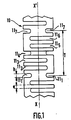
- FIG. 1 a spring 10 produced in a hollow cylindrical quartz tube in the case of a spring having a pitch with six recesses 111 to 11 6 .
- the recesses 11, and 11 7 are similar and are spaced apart by a step 7.
- the recesses are spaced e and offset in rotation relative to the axis XX 'by an angle of 360 ° / 6 ⁇ 60 ° in l 'example shown the width of each recess is h.
- FIGS. 2A to 2F represent the method of carrying out the invention in the case of a step with three recesses for the simplification of the drawing.
- a multi-wire saw is used for this, comprising for example three wires 20 1 , 20 2 , 20 3 spaced apart from each other by T. the width of the wires is substantially h.
- Three cuts are made 22 1 , 22 2 , 22 3 , with the direction of penetration represented by the arrow 21. The cuts are made until the wires are flush with the internal wall 25, that is to say after having passed through the entire hollow area 26 of the cylindrical tube.
- the tube is then rotated with respect to its axis by an angle of 360 ° / 3 - 120 °. the position of the letters A, B, C highlighting this rotation.
- the three wires are then moved along the longitudinal axis of the tube by a distance T / 3 and three new recesses are made 23 1 , 23 2 , 23 3 .
- the rotation and translation operations similar to the previous ones are carried out and then three other recesses are made.
- the pitch of rotation is 360 ° / n and the pitch of translation of each wire is T / n.
- FIGS. 3A to 3C represent a section, along the axis of symmetry of the tube, of a spring according to the invention but shown to facilitate drawing, in the case of a spring with a pitch with two recesses.
- This structure is very simplified but allows a better visualization of the forces used.
- the section according to FIG. 3A represents a part of the spring at rest.
- each recess for example 39, should preferably have a rounded structure. This is easily obtained by cutting using a wire saw.
- each recess such as 50
- the external edges of each recess preferably have a rounded structure. This can be obtained by operating a local chemical pickling carried out after the recesses have been made.
- the section according to FIG. 3C represents the same spring under conditions of compression with other directions of the forces 41, 42, 43 and 44 used. Again the preferred structure is that with rounded corners 49 and 60.
- FIGS. 3A to 3C represent a deliberately simplified example.
- the same balance of forces mechanisms are present, but in a much more complex manner, in springs according to the invention, with a number of recesses greater than 2 per step.
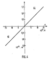
- the elongation curve as a function of the force is substantially linear. Its slope is approximately 10- 2 m / N. It operates both in compression (zone 41) and in extension (zone 42). This spring can also withstand low torsional forces.
- the ratio between the width of the cutout h and the distance e between two consecutive cuts can be over a wide range of values depending on the respective dimensions of h and e.
- the choice on the value h can also be very wide. It is possible to use wires, provided with abrasives, several millimeters in diameter and to make large recesses allowing the production of large springs.
- the sawing technique adapts correctly to these extreme conditions and allows economical production of springs made of non-metallic refractory material.
- the springs of non-metallic refractory material which have just been described can be used in applications which require the transmission or absorption of forces of low amplitude under conditions of high temperature for example to compensate for the expansions of moving parts.
- Such a spring can be used at temperatures exceeding 1000 ° C when it is made of quartz, graphite or boron nitride, while retaining its basic elastic properties. It is thus possible to obtain a spring with a material in the amorphous state having qualities analogous to a metal spring but suitable for high temperatures.
Landscapes
- Engineering & Computer Science (AREA)
- Chemical & Material Sciences (AREA)
- Ceramic Engineering (AREA)
- Mechanical Engineering (AREA)
- General Engineering & Computer Science (AREA)
- Manufacturing & Machinery (AREA)
- Materials Engineering (AREA)
- Structural Engineering (AREA)
- Organic Chemistry (AREA)
- Springs (AREA)
Claims (8)
Applications Claiming Priority (2)
| Application Number | Priority Date | Filing Date | Title |
|---|---|---|---|
| FR8515653 | 1985-10-22 | ||
| FR8515653A FR2588928B1 (fr) | 1985-10-22 | 1985-10-22 | Ressort de type cylindrique utilisable aux hautes temperatures et procede de realisation d'un tel ressort |
Publications (2)
| Publication Number | Publication Date |
|---|---|
| EP0220769A1 EP0220769A1 (de) | 1987-05-06 |
| EP0220769B1 true EP0220769B1 (de) | 1989-01-04 |
Family
ID=9324080
Family Applications (1)
| Application Number | Title | Priority Date | Filing Date |
|---|---|---|---|
| EP86201815A Expired EP0220769B1 (de) | 1985-10-22 | 1986-10-20 | Verfahren zur Herstellung einer bei hoher Temperatur verwendbaren Feder vom zylindrischen Typ |
Country Status (5)
| Country | Link |
|---|---|
| US (1) | US4826143A (de) |
| EP (1) | EP0220769B1 (de) |
| JP (1) | JPS62101929A (de) |
| DE (1) | DE3661647D1 (de) |
| FR (1) | FR2588928B1 (de) |
Families Citing this family (10)
| Publication number | Priority date | Publication date | Assignee | Title |
|---|---|---|---|---|
| US5062619A (en) * | 1989-04-03 | 1991-11-05 | Nabeya Kogyo Co., Ltd. | Non-linear spring |
| US5041315A (en) * | 1989-05-15 | 1991-08-20 | Zircoa Inc. | Flexible ceramic member and method of production thereof |
| US5982187A (en) * | 1993-07-01 | 1999-11-09 | Alphatest Corporation | Resilient connector having a tubular spring |
| US6034532A (en) * | 1993-07-01 | 2000-03-07 | Alphatest Corporation | Resilient connector having a tubular spring |
| FR2772748B1 (fr) * | 1997-12-22 | 2000-03-17 | Snecma | Procede de fabrication de ressort en materiau composite thermostructural |
| JP2001221269A (ja) * | 2000-02-07 | 2001-08-17 | Super Silicon Kenkyusho:Kk | 石英コイルスプリングとその製造法 |
| DE10149746C1 (de) * | 2001-10-09 | 2003-05-28 | Siemens Ag | Verfahren zur Herstellung einer Rohrfeder sowie Aktoreinheit mit einer solchen Rohrfeder |
| TWI399354B (zh) | 2007-06-07 | 2013-06-21 | Ibiden Co Ltd | 石墨材料及石墨材料之製造方法 |
| CN102312949A (zh) * | 2011-10-13 | 2012-01-11 | 浙江大学台州研究院 | 用于眼镜弹性铰链的螺旋弹簧的制造方法 |
| KR101836983B1 (ko) * | 2015-07-16 | 2018-04-19 | 김형우 | 스프링구조체의 제조방법. |
Family Cites Families (23)
| Publication number | Priority date | Publication date | Assignee | Title |
|---|---|---|---|---|
| CA761814A (en) * | 1967-06-27 | Remoleur Jacques | Fall-damping device | |
| US1557958A (en) * | 1924-08-26 | 1925-10-20 | American Mach & Foundry | Flexible coupling |
| BE353934A (de) * | 1927-09-16 | |||
| FR938493A (fr) * | 1944-05-17 | 1948-09-16 | Linde Air Prod Co | Procédé de formation à chaud d'un corps monocristallin de corindon ou de spinelle, et corps monocristallin obtenu par ce procédé |
| FR57458E (fr) * | 1947-07-19 | 1953-01-28 | Linde Air Prod Co | Procédé de formation à chaud d'un corps monocristallin de corindon ou de spinelle, et corps monocristallin obtenu par ce procédé |
| FR1090004A (fr) * | 1953-07-22 | 1955-03-25 | Ressort | |
| US2854230A (en) * | 1955-10-31 | 1958-09-30 | Vibradamp Corp | Glass fiber spring unit and method of making same |
| US2888258A (en) * | 1956-05-11 | 1959-05-26 | Hoffstrom Bo Nilsson | Springs |
| US2852424A (en) * | 1957-04-30 | 1958-09-16 | Frank W Reinhart | Reinforced plastic springs |
| US3524636A (en) * | 1968-03-20 | 1970-08-18 | United Aircraft Corp | Cast single crystal spring element |
| US3720740A (en) * | 1970-06-24 | 1973-03-13 | Hitachi Ltd | Low pressure sintering of boron nitride using low thermal expansion static sintering molds |
| AU7709975A (en) * | 1974-01-16 | 1976-07-08 | Saturnini E | Cage-like spring |
| FR2404770A2 (fr) * | 1975-03-06 | 1979-04-27 | Pean Pierre | Organe elastique |
| CH610805A5 (en) * | 1975-11-07 | 1979-05-15 | Sotarem Sa | Machine for cutting hard bodies |
| US4092972A (en) * | 1977-02-11 | 1978-06-06 | Crystal Systems, Inc. | Process of cutting wafers |
| DE3117567C2 (de) * | 1980-05-02 | 1983-05-11 | Fukuvi Chemical Industry Co., Ltd., Fukui | Verfahren zur Bereitung formbarer, biegsamer Graphitkörnchen, sowie deren Verwendung zur Herstellung von Graphitformkörpern |
| US4288064A (en) * | 1980-05-05 | 1981-09-08 | Austen Alfred R | Timed-action actuators |
| JPS5722436A (en) * | 1980-07-16 | 1982-02-05 | Nhk Spring Co Ltd | Vibration damper |
| US4372531A (en) * | 1980-11-18 | 1983-02-08 | Maxon Corporation | Ceramic gate valve and components therefor |
| JPS57188464A (en) * | 1981-05-11 | 1982-11-19 | Mitsubishi Pencil Co | Carbon spring and manufacture |
| DE3216200A1 (de) * | 1982-04-30 | 1983-11-03 | Wacker-Chemitronic Gesellschaft für Elektronik-Grundstoffe mbH, 8263 Burghausen | Verfahren zum saegen von kristallstaeben und mehrblattinnenlochsaege zur durchfuehrung des verfahrens |
| US4669172A (en) * | 1983-02-07 | 1987-06-02 | Circon Corporation | Method for fabrication of flexible shaft |
| US4650619A (en) * | 1983-12-29 | 1987-03-17 | Toshiba Ceramics Co., Ltd. | Method of machining a ceramic member |
-
1985
- 1985-10-22 FR FR8515653A patent/FR2588928B1/fr not_active Expired
-
1986
- 1986-10-20 DE DE8686201815T patent/DE3661647D1/de not_active Expired
- 1986-10-20 JP JP61247659A patent/JPS62101929A/ja active Pending
- 1986-10-20 EP EP86201815A patent/EP0220769B1/de not_active Expired
-
1988
- 1988-08-12 US US07/232,550 patent/US4826143A/en not_active Expired - Fee Related
Also Published As
| Publication number | Publication date |
|---|---|
| DE3661647D1 (en) | 1989-02-09 |
| EP0220769A1 (de) | 1987-05-06 |
| FR2588928B1 (fr) | 1989-09-01 |
| JPS62101929A (ja) | 1987-05-12 |
| FR2588928A1 (fr) | 1987-04-24 |
| US4826143A (en) | 1989-05-02 |
Similar Documents
| Publication | Publication Date | Title |
|---|---|---|
| EP0220769B1 (de) | Verfahren zur Herstellung einer bei hoher Temperatur verwendbaren Feder vom zylindrischen Typ | |
| EP0143032B1 (de) | Verfahren zur Herstellung von Mehrfachkeilriemenscheiben und Scheibe dazu | |
| FR2464401A1 (fr) | Coussinet de palier a feuille et a jeu reglable, ainsi qu'un procede de fabrication d'un element en feuille pour ce coussinet de palier | |
| FR2495508A1 (fr) | Procede pour fabriquer des poulies par roulage a partir d'une feuille metallique et poulies ainsi obtenues | |
| EP0148088A2 (de) | Elastische Metalldichtung mit hervorstehenden Teilen, welche verschwinden | |
| WO2013135895A1 (fr) | Fil a scier, methode et installation de fabrication d'un tel fil et utilisation | |
| EP0242263A2 (de) | Keilriemen zur Antriebsübertragung und Verfahren zu dessen Herstellung | |
| EP0707941B1 (de) | Verfahren und Vorrichtung zum Herstellen von Rohren aus Verbundwerkstoff mit guten mechanischen und tribologischen Eigenschaften, und durch das Verfahren hergestellte Rohre | |
| FR2633213A1 (fr) | Procede de realisation d'une preforme fibreuse pour la fabrication de pieces en materiau composite ayant une forme complexe | |
| FR2856078A1 (fr) | Revetement pour une piece mecanique comprenant au moins du carbone amorphe hydrogene et procede de depot d'un tel revetement. | |
| EP1366306A1 (de) | Zylinderrollenlager aus nitrierstahl | |
| EP0177418B1 (de) | Vorrichtung zum Schneiden eines Papperohres mit einer harter Oberfläche | |
| FR2519066A2 (fr) | Filtre ou crepine pour puits, forme par enroulement de filaments, procede et appareil pour sa fabrication | |
| EP0773306A1 (de) | Rostfreier ferritischer Stahl, verwendbar zur Herstellung von Stahlwolle | |
| EP4521172A1 (de) | Werkzeug und verfahren zur trennung von spiralfedern nach dem gleiten und wärmebehandlung | |
| FR2529504A1 (fr) | Outil et procede pour le decoupage precis de pieces cylindriques dans des materiaux elastiques poreux ou alveolaires | |
| WO2014202906A1 (fr) | Ensemble de plaques ou de pieces obtenues par decoupe d'un bloc en materiau metallique ou composite. | |
| EP1473503B1 (de) | Gewellter Schlauch mit zumindest einem metallischen Verstärkungsring und Verfahren zu dessen Herstellung. | |
| FR2655904A1 (fr) | Systeme de decoupe de corps solides du type "a cable". | |
| EP0227125B1 (de) | Tiegel zur Flüssigphasenepitaxie von Halbleiterschichten | |
| FR2959516A1 (fr) | Procede de pretraitement de structuration d'une surface de coulissement | |
| EP1447152A1 (de) | Vorrichtung zum spitzbogenförmig Formen ,zum Fliessdrehen, oder zum Fliessstanzen von metallischen Werkstücken mit kreisförmigem oder eiförmigem Querschnitt | |
| FR2637827A1 (fr) | Systeme de decoupe de corps solides du type " a cable " | |
| EP0988950A1 (de) | Steinsägeverfahren, diamantiertes Schneidsegment und Sägeblatt versehen mit diesem Segment | |
| FR2481767A1 (fr) | Rondelle elastique d'arret et son procede de fabrication |
Legal Events
| Date | Code | Title | Description |
|---|---|---|---|
| PUAI | Public reference made under article 153(3) epc to a published international application that has entered the european phase |
Free format text: ORIGINAL CODE: 0009012 |
|
| AK | Designated contracting states |
Kind code of ref document: A1 Designated state(s): DE FR GB IT NL |
|
| 17P | Request for examination filed |
Effective date: 19870720 |
|
| 17Q | First examination report despatched |
Effective date: 19880314 |
|
| GRAA | (expected) grant |
Free format text: ORIGINAL CODE: 0009210 |
|
| AK | Designated contracting states |
Kind code of ref document: B1 Designated state(s): DE FR GB IT NL |
|
| REF | Corresponds to: |
Ref document number: 3661647 Country of ref document: DE Date of ref document: 19890209 |
|
| ITF | It: translation for a ep patent filed | ||
| GBT | Gb: translation of ep patent filed (gb section 77(6)(a)/1977) | ||
| PGFP | Annual fee paid to national office [announced via postgrant information from national office to epo] |
Ref country code: NL Payment date: 19891031 Year of fee payment: 4 |
|
| PLBE | No opposition filed within time limit |
Free format text: ORIGINAL CODE: 0009261 |
|
| STAA | Information on the status of an ep patent application or granted ep patent |
Free format text: STATUS: NO OPPOSITION FILED WITHIN TIME LIMIT |
|
| 26N | No opposition filed | ||
| REG | Reference to a national code |
Ref country code: FR Ref legal event code: CD |
|
| PGFP | Annual fee paid to national office [announced via postgrant information from national office to epo] |
Ref country code: GB Payment date: 19901001 Year of fee payment: 5 |
|
| PGFP | Annual fee paid to national office [announced via postgrant information from national office to epo] |
Ref country code: FR Payment date: 19901023 Year of fee payment: 5 |
|
| ITTA | It: last paid annual fee | ||
| PGFP | Annual fee paid to national office [announced via postgrant information from national office to epo] |
Ref country code: DE Payment date: 19901218 Year of fee payment: 5 |
|
| PG25 | Lapsed in a contracting state [announced via postgrant information from national office to epo] |
Ref country code: NL Effective date: 19910501 |
|
| NLV4 | Nl: lapsed or anulled due to non-payment of the annual fee | ||
| PG25 | Lapsed in a contracting state [announced via postgrant information from national office to epo] |
Ref country code: GB Effective date: 19911020 |
|
| GBPC | Gb: european patent ceased through non-payment of renewal fee | ||
| PG25 | Lapsed in a contracting state [announced via postgrant information from national office to epo] |
Ref country code: FR Effective date: 19920630 |
|
| PG25 | Lapsed in a contracting state [announced via postgrant information from national office to epo] |
Ref country code: DE Effective date: 19920701 |
|
| REG | Reference to a national code |
Ref country code: FR Ref legal event code: ST |
|
| PG25 | Lapsed in a contracting state [announced via postgrant information from national office to epo] |
Ref country code: IT Free format text: LAPSE BECAUSE OF NON-PAYMENT OF DUE FEES;WARNING: LAPSES OF ITALIAN PATENTS WITH EFFECTIVE DATE BEFORE 2007 MAY HAVE OCCURRED AT ANY TIME BEFORE 2007. THE CORRECT EFFECTIVE DATE MAY BE DIFFERENT FROM THE ONE RECORDED. Effective date: 20051020 |