EP4521172A1 - Werkzeug und verfahren zur trennung von spiralfedern nach dem gleiten und wärmebehandlung - Google Patents
Werkzeug und verfahren zur trennung von spiralfedern nach dem gleiten und wärmebehandlung Download PDFInfo
- Publication number
- EP4521172A1 EP4521172A1 EP23195657.4A EP23195657A EP4521172A1 EP 4521172 A1 EP4521172 A1 EP 4521172A1 EP 23195657 A EP23195657 A EP 23195657A EP 4521172 A1 EP4521172 A1 EP 4521172A1
- Authority
- EP
- European Patent Office
- Prior art keywords
- rolling surface
- plate
- tool
- tooling
- lower rolling
- Prior art date
- Legal status (The legal status is an assumption and is not a legal conclusion. Google has not performed a legal analysis and makes no representation as to the accuracy of the status listed.)
- Pending
Links
Images

Classifications
-
- G—PHYSICS
- G04—HOROLOGY
- G04B—MECHANICALLY-DRIVEN CLOCKS OR WATCHES; MECHANICAL PARTS OF CLOCKS OR WATCHES IN GENERAL; TIME PIECES USING THE POSITION OF THE SUN, MOON OR STARS
- G04B17/00—Mechanisms for stabilising frequency
- G04B17/04—Oscillators acting by spring tension
- G04B17/06—Oscillators with hairsprings, e.g. balance
- G04B17/066—Manufacture of the spiral spring
-
- B—PERFORMING OPERATIONS; TRANSPORTING
- B65—CONVEYING; PACKING; STORING; HANDLING THIN OR FILAMENTARY MATERIAL
- B65G—TRANSPORT OR STORAGE DEVICES, e.g. CONVEYORS FOR LOADING OR TIPPING, SHOP CONVEYOR SYSTEMS OR PNEUMATIC TUBE CONVEYORS
- B65G47/00—Article or material-handling devices associated with conveyors; Methods employing such devices
- B65G47/22—Devices influencing the relative position or the attitude of articles during transit by conveyors
-
- B—PERFORMING OPERATIONS; TRANSPORTING
- B65—CONVEYING; PACKING; STORING; HANDLING THIN OR FILAMENTARY MATERIAL
- B65G—TRANSPORT OR STORAGE DEVICES, e.g. CONVEYORS FOR LOADING OR TIPPING, SHOP CONVEYOR SYSTEMS OR PNEUMATIC TUBE CONVEYORS
- B65G27/00—Jigging conveyors
- B65G27/10—Applications of devices for generating or transmitting jigging movements
- B65G27/16—Applications of devices for generating or transmitting jigging movements of vibrators, i.e. devices for producing movements of high frequency and small amplitude
-
- B—PERFORMING OPERATIONS; TRANSPORTING
- B65—CONVEYING; PACKING; STORING; HANDLING THIN OR FILAMENTARY MATERIAL
- B65G—TRANSPORT OR STORAGE DEVICES, e.g. CONVEYORS FOR LOADING OR TIPPING, SHOP CONVEYOR SYSTEMS OR PNEUMATIC TUBE CONVEYORS
- B65G47/00—Article or material-handling devices associated with conveyors; Methods employing such devices
- B65G47/74—Feeding, transfer, or discharging devices of particular kinds or types
- B65G47/82—Rotary or reciprocating members for direct action on articles or materials, e.g. pushers, rakes, shovels
-
- G—PHYSICS
- G04—HOROLOGY
- G04D—APPARATUS OR TOOLS SPECIALLY DESIGNED FOR MAKING OR MAINTAINING CLOCKS OR WATCHES
- G04D3/00—Watchmakers' or watch-repairers' machines or tools for working materials
- G04D3/0002—Watchmakers' or watch-repairers' machines or tools for working materials for mechanical working other than with a lathe
- G04D3/0005—Watchmakers' or watch-repairers' machines or tools for working materials for mechanical working other than with a lathe for parts of driving means
- G04D3/0007—Watchmakers' or watch-repairers' machines or tools for working materials for mechanical working other than with a lathe for parts of driving means for springs
-
- G—PHYSICS
- G04—HOROLOGY
- G04D—APPARATUS OR TOOLS SPECIALLY DESIGNED FOR MAKING OR MAINTAINING CLOCKS OR WATCHES
- G04D3/00—Watchmakers' or watch-repairers' machines or tools for working materials
- G04D3/0002—Watchmakers' or watch-repairers' machines or tools for working materials for mechanical working other than with a lathe
- G04D3/0035—Watchmakers' or watch-repairers' machines or tools for working materials for mechanical working other than with a lathe for components of the regulating mechanism
- G04D3/0041—Watchmakers' or watch-repairers' machines or tools for working materials for mechanical working other than with a lathe for components of the regulating mechanism for coil-springs
-
- B—PERFORMING OPERATIONS; TRANSPORTING
- B65—CONVEYING; PACKING; STORING; HANDLING THIN OR FILAMENTARY MATERIAL
- B65G—TRANSPORT OR STORAGE DEVICES, e.g. CONVEYORS FOR LOADING OR TIPPING, SHOP CONVEYOR SYSTEMS OR PNEUMATIC TUBE CONVEYORS
- B65G2201/00—Indexing codes relating to handling devices, e.g. conveyors, characterised by the type of product or load being conveyed or handled
- B65G2201/02—Articles
-
- F—MECHANICAL ENGINEERING; LIGHTING; HEATING; WEAPONS; BLASTING
- F16—ENGINEERING ELEMENTS AND UNITS; GENERAL MEASURES FOR PRODUCING AND MAINTAINING EFFECTIVE FUNCTIONING OF MACHINES OR INSTALLATIONS; THERMAL INSULATION IN GENERAL
- F16F—SPRINGS; SHOCK-ABSORBERS; MEANS FOR DAMPING VIBRATION
- F16F1/00—Springs
- F16F1/02—Springs made of steel or other material having low internal friction; Wound, torsion, leaf, cup, ring or the like springs, the material of the spring not being relevant
- F16F1/024—Covers or coatings therefor
-
- F—MECHANICAL ENGINEERING; LIGHTING; HEATING; WEAPONS; BLASTING
- F16—ENGINEERING ELEMENTS AND UNITS; GENERAL MEASURES FOR PRODUCING AND MAINTAINING EFFECTIVE FUNCTIONING OF MACHINES OR INSTALLATIONS; THERMAL INSULATION IN GENERAL
- F16F—SPRINGS; SHOCK-ABSORBERS; MEANS FOR DAMPING VIBRATION
- F16F1/00—Springs
- F16F1/02—Springs made of steel or other material having low internal friction; Wound, torsion, leaf, cup, ring or the like springs, the material of the spring not being relevant
- F16F1/04—Wound springs
- F16F1/10—Spiral springs with turns lying substantially in plane surfaces
-
- F—MECHANICAL ENGINEERING; LIGHTING; HEATING; WEAPONS; BLASTING
- F16—ENGINEERING ELEMENTS AND UNITS; GENERAL MEASURES FOR PRODUCING AND MAINTAINING EFFECTIVE FUNCTIONING OF MACHINES OR INSTALLATIONS; THERMAL INSULATION IN GENERAL
- F16F—SPRINGS; SHOCK-ABSORBERS; MEANS FOR DAMPING VIBRATION
- F16F2226/00—Manufacturing; Treatments
-
- G—PHYSICS
- G04—HOROLOGY
- G04B—MECHANICALLY-DRIVEN CLOCKS OR WATCHES; MECHANICAL PARTS OF CLOCKS OR WATCHES IN GENERAL; TIME PIECES USING THE POSITION OF THE SUN, MOON OR STARS
- G04B1/00—Driving mechanisms
- G04B1/10—Driving mechanisms with mainspring
- G04B1/14—Mainsprings; Bridles therefor
- G04B1/145—Composition and manufacture of the springs
Definitions
- the invention further relates to a method of separating spiral springs from a plate after stripping and heat treatment.
- Oscillator spiral springs are formed by wrapping (winding) between 3 and 6 metal strips to form a spiral plate; this creates an Archimedean spiral with a regular pitch between each turn. The plates are then heat-treated (fixed) to maintain this spiral shape. This method creates a large contact surface between the small metal strips, and the step of separating the spirals can be complicated: the spirals are then said to "stick". This problem is particularly present when the spiral spring material is a titanium-based alloy, whereas steel spirals generally do not present separation problems.
- a traditional method for separating hairsprings is to place them in a small cardboard box and tap the box by hand on a hard surface.
- a similar but more industrial method is to use a tapping machine, which generates repeated shocks on the balance springs by means of a cam and springs.
- the invention proposes to develop another method of separating the hairsprings, based on mechanical crushing of the hairsprings before their passage through the typing machine.
- said tooling comprises a first lower rolling surface and a second upper rolling surface parallel or substantially parallel to each other and to a base plane, and movable relative to each other, on the one hand in a longitudinal direction parallel to said base plane, and on the other hand in a vertical direction perpendicular to said base plane, and arranged to clamp said plate between a lower generatrix and an upper generatrix under the action of at least one actuator arranged to bring said first lower rolling surface and said second upper rolling surface closer to each other to deform said plate by ovalization, and to subject a substantially cylindrical peripheral surface of said plate to a rolling movement between said first lower rolling surface and said second upper rolling surface under the action of at least one actuator arranged to impart a relative movement along said longitudinal direction between said first lower rolling surface and said second upper rolling surface.
- Another aspect of the invention relates to a method of separating spiral springs from a plate after stripping and heat treatment.
- such a tool is provided to carry out a mechanical crushing of said plate in the elastic domain, minimum and maximum values of crushing rate of a substantially cylindrical peripheral surface of said plate are determined, said plate is subjected to at least one said rolling sequence in a compressed position, minimum and maximum rotation values are determined per sequence, minimum and maximum cumulative rotation values are determined for a set of sequences, the number of which is determined, a said plate is positioned between said first lower rolling surface and said second upper rolling surface of said tool, by the action of an operator or a robotic manipulator, and successively executed, for each said sequence, a first step of compressing said plate by a predetermined vertical stroke, a second step of relative movement between said first lower rolling surface and said second upper rolling surface according to a predetermined longitudinal stroke, a third step of relative disengagement between said first lower rolling surface and said second upper rolling surface towards a spacing position in which said plate is not subject to no compressive stress.
- the invention relates to a process of mechanical crushing in the elastic domain of plates of strapped and fixed hairsprings, which makes it possible to significantly improve the separation rate of the hairsprings.
- Crushing rolling consists of subjecting the spiral plates, directly after fixing, to a mechanical stress which will deform them elastically, in order to help the blades detach from the spirals between them and facilitate the separation process. It is therefore important to note that this rolling is not strictly speaking a separation method, but it is a preliminary step which allows, if carried out correctly, to significantly reduce the reject rate during separation.
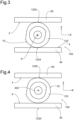
- a mechanical actuator which can be the same as that controlling the crushing, induces a lateral displacement in a longitudinal direction X; this will rotate the spiral plate 123 (hence the term "rolling"), while maintaining the crushing in the vertical direction Z.
- This produces a tensile stress that will successively affect all portions of the blades, as the spiral plate 123 rolls.
- the crush rolling process is regulated by several critical parameters.
- the crushing rate is a key parameter, because it will determine the intensity of the tensile stresses which will help the detachment of the blades. However, it must not be too large, to avoid plastic deformation of the spiral plate 123. It is preferably chosen in the range varying between 1.5% and 5.6% of the diameter of the spiral plate 123.
- spiral plates are introduced so that they roll in the opposite direction to the winding of the Archimedean spiral, otherwise the ends of the blades on the periphery of the spiral plate 123 can catch on the base and plastically deform the spiral.
- a plate is advantageously placed, in particular a plexiglass window, which has the role of limiting the movement of the plates in this transverse direction Y, by providing the necessary spacing for rolling with a minimum of friction, and it also allows the blades to be pinned together at regular intervals.
- the invention is based on the use of a tool 100 for separating a substantially cylindrical or annular plate 123 of spiral springs 1, 2, 3, after stripping and heat treatment.
- This tool 100 is arranged to initiate or carry out the separation of the spirals 1, 2, 3.
- This first lower rolling surface 4 and this second upper rolling surface 5 are arranged to clamp the plate 123 between a lower generatrix 1234 and an upper generatrix 1235 under the action of at least one actuator 6, 7, arranged to bring the first lower rolling surface 4 and the second upper rolling surface 5 closer to each other to deform the plate 123 by ovalization.
- the tool 100 comprises control means 200 which are arranged to control a vertical stroke, in the vertical direction Z, of the first lower rolling surface 4 relative to the second upper rolling surface 5 and to control a longitudinal stroke, in the longitudinal direction X, of the first lower rolling surface 4 relative to the second upper rolling surface 5.
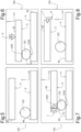
- control means 200 are arranged to control at least one sequence comprising, after positioning the plate 123 between the first lower rolling surface 4 and the second upper rolling surface 5 by an operator or a robotic manipulator, a first step of compressing the plate 123 by a predetermined vertical stroke of the first actuator 6, a second step of relative movement between the first lower rolling surface 4 and the second upper rolling surface 5 according to a predetermined longitudinal stroke, a third step of relative disengagement between the first lower rolling surface 4 and the second upper rolling surface 5 towards a spacing position in which the plate 123 is not subjected to any compressive stress.
- the predetermined vertical stroke is between 1.5% and 5.6% of the maximum diameter of the substantially cylindrical peripheral surface 10 of the plate 123.
- the predetermined longitudinal stroke is arranged to impart to the plate 123 a rotation of between 1/8 turn and 1 turn.
- control means 200 are arranged to control, in at least one sequence, a fourth step of relative return movement between the first lower rolling surface 4 and the second upper rolling surface 5 to bring them back into the relative position that they occupy with respect to each other in the first step.
- control means 200 are arranged to control a plurality of such sequences with a cumulative rotation of the plate 123 of between 0.5 turns and 100 turns.
- control means 200 are arranged to control a plurality of such sequences with a cumulative rotation of the plate 123 of between 2 turns and 4 turns.
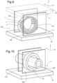
- the tool 100 comprises, transversely in a transverse direction Y perpendicular to the longitudinal direction X and to the vertical direction Z, at least one plate 400 comprising a flat surface for limiting the transverse travel of the plate 123. More particularly, the tool 100 comprises, transversely and on either side of the plate 123, two such plates for limiting the transverse travel of the plate 123, at least one of which is transparent.
- the tool 100 comprises a mandrel 300 insertable into a said plate 123 and arranged to limit its travel during its manipulation in the tool 100.
- the mandrel 300 is dimensioned, relative to a plate 123 of given geometry, with a radial clearance which is greater than the predetermined vertical travel, which is a maximum compression travel controlled by the control means 200. More particularly, this mandrel 300 is guided by housings or journals which comprise two such parallel plates 400.
- first lower rolling surface 4 is a surface of a rigid lower plate 40 and/or the second upper rolling surface 5 is a surface of a rigid upper plate 50.
- the first lower rolling surface 4 and/or the second upper rolling surface 5 is a flat surface.
- the first lower rolling surface 4 and/or the second upper rolling surface 5 comprise a corrugation. More particularly, this corrugation is aperiodic.
- first lower rolling surface 4 and the second upper rolling surface 5 are orientable relative to each other in a position in which planes which are internally tangent to them, on the side of the plate 123, are inclined relative to each other at a predetermined angle and of a value less than 5°.
- the tool 100 comprises a first actuator 6, which is arranged to bring the first lower rolling surface 4 and the second upper rolling surface 5 closer to each other in the vertical direction Z to deform the plate 123 by ovalization.
- the tool 100 comprises a second actuator 7, which is arranged to subject a substantially cylindrical peripheral surface 10 of the plate 123 to a rolling movement on the first lower rolling surface 4 and the second upper rolling surface 5. More particularly, the second actuator 7 is arranged to control a relative movement in the longitudinal direction X between the first lower rolling surface 4 and the second upper rolling surface 5.
- the second actuator 7 is merged with the first actuator 6 which is the only actuator included in the tool 100, and which includes switching means for separately controlling a relative movement between the first rolling surface lower 4 and the second upper rolling surface 5, in the vertical direction Z or in the longitudinal direction X.
- control means 200 are manual.
- the invention also relates to a method for separating spiral springs 1, 2, 3, from a plate 123 after stripping and heat treatment.
- such a tool 100 is provided to carry out mechanical crushing of the plate 123 in the elastic domain, minimum and maximum values of the crushing rate of a substantially cylindrical peripheral surface 10 of the plate 123 are determined, the plate 123 is subjected to at least one rolling sequence in a compressed position, minimum and maximum rotation values are determined per sequence, minimum and maximum cumulative rotation values are determined for a set of sequences, the number of which is determined, a plate 123 is positioned between the first lower rolling surface 4 and the second upper rolling surface 5 of the tool 100, by the action of an operator or a robotic manipulator, and successively, for each sequence, a first step of compressing the plate 123 by a predetermined vertical stroke, a second step of relative movement between the first lower rolling surface 4 and the second upper rolling surface 5 according to a longitudinal stroke predetermined, a third step of relative clearance between the first lower rolling surface 4 and the second upper rolling surface 5 towards a spacing position in which the plate 123 is not subjected to any compressive stress.
- the blades of the springs 1, 2, 3 are radially crushed at regular intervals.
- the blades of the springs 1, 2, 3 are radially crushed at irregular intervals between the first lower rolling surface 4 and the second upper rolling surface 5.
- a mechanical separation of the springs 1, 2, 3 is carried out, by placing the plate 123 in a cardboard box which is subjected to shocks on a rigid surface, and/or by subjecting the plate 123 to a tapping machine generating repeated shocks on the spiral springs 1, 2, 3 of the plate 123.
- the separation is assisted by rolling crushing carried out in the elastic domain of the material, and this process leaves no trace on the hairspring.
- This process of separating the hairsprings makes it possible to increase the rate of separated hairsprings significantly, for hairsprings made from titanium alloy, and to significantly increase the proportion of hairsprings suitable for service.
Landscapes
- Engineering & Computer Science (AREA)
- Physics & Mathematics (AREA)
- General Physics & Mathematics (AREA)
- Mechanical Engineering (AREA)
- Manufacturing & Machinery (AREA)
- Springs (AREA)
- Crushing And Grinding (AREA)
- Finish Polishing, Edge Sharpening, And Grinding By Specific Grinding Devices (AREA)
Priority Applications (4)
| Application Number | Priority Date | Filing Date | Title |
|---|---|---|---|
| EP23195657.4A EP4521172A1 (de) | 2023-09-06 | 2023-09-06 | Werkzeug und verfahren zur trennung von spiralfedern nach dem gleiten und wärmebehandlung |
| JP2024114476A JP7749074B2 (ja) | 2023-09-06 | 2024-07-18 | 巻き及び熱処理の後にバランスばねを分離するための工具及び方法 |
| US18/810,616 US20250076812A1 (en) | 2023-09-06 | 2024-08-21 | Tool and method for the separation of balance springs after winding in and heat treatment |
| CN202411239714.8A CN119568701A (zh) | 2023-09-06 | 2024-09-05 | 用于在卷绕和热处理之后分离摆轮游丝的工具和方法 |
Applications Claiming Priority (1)
| Application Number | Priority Date | Filing Date | Title |
|---|---|---|---|
| EP23195657.4A EP4521172A1 (de) | 2023-09-06 | 2023-09-06 | Werkzeug und verfahren zur trennung von spiralfedern nach dem gleiten und wärmebehandlung |
Publications (1)
| Publication Number | Publication Date |
|---|---|
| EP4521172A1 true EP4521172A1 (de) | 2025-03-12 |
Family
ID=87934009
Family Applications (1)
| Application Number | Title | Priority Date | Filing Date |
|---|---|---|---|
| EP23195657.4A Pending EP4521172A1 (de) | 2023-09-06 | 2023-09-06 | Werkzeug und verfahren zur trennung von spiralfedern nach dem gleiten und wärmebehandlung |
Country Status (4)
| Country | Link |
|---|---|
| US (1) | US20250076812A1 (de) |
| EP (1) | EP4521172A1 (de) |
| JP (1) | JP7749074B2 (de) |
| CN (1) | CN119568701A (de) |
Families Citing this family (1)
| Publication number | Priority date | Publication date | Assignee | Title |
|---|---|---|---|---|
| EP4575679A1 (de) * | 2023-12-19 | 2025-06-25 | Nivarox-FAR S.A. | Vorrichtung zum trennen von aufgewunden spiralfedern nach einem entspannungszyklus und verfahren zur herstellung einer spiralfeder mit einer solchen vorrichtung |
Citations (3)
| Publication number | Priority date | Publication date | Assignee | Title |
|---|---|---|---|---|
| EP0811436A1 (de) * | 1996-06-06 | 1997-12-10 | Sango Co., Ltd. | Verfahren zur Herstellung eines Rohres |
| JPH11197777A (ja) * | 1998-01-14 | 1999-07-27 | Matsui Seisakusho:Kk | 駆動軸用異形チューブ製造方法 |
| FR3107365A1 (fr) * | 2020-02-17 | 2021-08-20 | Philippe RHUL | « Procédé pour fabriquer un spiral d’un mouvement d’horlogerie, appareil de fabrication pour la mise en œuvre du procédé, et spiraux ainsi produits » |
Family Cites Families (5)
| Publication number | Priority date | Publication date | Assignee | Title |
|---|---|---|---|---|
| JPS5255666A (en) * | 1975-05-28 | 1977-05-07 | Seiko Epson Corp | Method of unfastening balance springs |
| JPS53122459A (en) * | 1977-03-31 | 1978-10-25 | Sendai Seimitsu Zairiyou Kenki | Device for unravelling hair spring |
| GB0324439D0 (en) * | 2003-10-20 | 2003-11-19 | Levingston Gideon R | Minimal thermal variation and temperature compensating non-magnetic balance wheels and methods of production of these and their associated balance springs |
| JP6134523B2 (ja) * | 2013-01-30 | 2017-05-24 | セイコーインスツル株式会社 | ばねの製造方法 |
| JP2017090390A (ja) * | 2015-11-16 | 2017-05-25 | セイコーエプソン株式会社 | ひげぜんまい、時計ムーブメント、時計、および、ひげぜんまいの製造方法 |
-
2023
- 2023-09-06 EP EP23195657.4A patent/EP4521172A1/de active Pending
-
2024
- 2024-07-18 JP JP2024114476A patent/JP7749074B2/ja active Active
- 2024-08-21 US US18/810,616 patent/US20250076812A1/en active Pending
- 2024-09-05 CN CN202411239714.8A patent/CN119568701A/zh active Pending
Patent Citations (3)
| Publication number | Priority date | Publication date | Assignee | Title |
|---|---|---|---|---|
| EP0811436A1 (de) * | 1996-06-06 | 1997-12-10 | Sango Co., Ltd. | Verfahren zur Herstellung eines Rohres |
| JPH11197777A (ja) * | 1998-01-14 | 1999-07-27 | Matsui Seisakusho:Kk | 駆動軸用異形チューブ製造方法 |
| FR3107365A1 (fr) * | 2020-02-17 | 2021-08-20 | Philippe RHUL | « Procédé pour fabriquer un spiral d’un mouvement d’horlogerie, appareil de fabrication pour la mise en œuvre du procédé, et spiraux ainsi produits » |
Also Published As
| Publication number | Publication date |
|---|---|
| JP7749074B2 (ja) | 2025-10-03 |
| CN119568701A (zh) | 2025-03-07 |
| JP2025037796A (ja) | 2025-03-18 |
| US20250076812A1 (en) | 2025-03-06 |
Similar Documents
| Publication | Publication Date | Title |
|---|---|---|
| EP2458232A1 (de) | Befestigungsorgan mit Endhohlraum in einem Endteil mit Gewinde, Stiftelement, Betätigungswerkzeug und Kaliber, das ein solches Stiftelement enthält | |
| EP0165083B1 (de) | Verfahren zur Wiederherstellung von Labyrinthdichtungen, insbesondere für Turbomaschinen und Werkzeuge dafür | |
| EP1591190B1 (de) | Verfahren zum Verschweissen zweier Metallbleche | |
| CH721110A2 (fr) | Outillage et procédé de séparation de ressorts spiraux après estrapadage et traitement thermique | |
| CH502855A (fr) | Procédé de profilage d'une ébauche cylindrique pleine, et laminoir pour sa mise en oeuvre | |
| US20250076812A1 (en) | Tool and method for the separation of balance springs after winding in and heat treatment | |
| EP2833006B1 (de) | Schraube mit begrenztem Anzugsdrehmoment | |
| EP1399278A2 (de) | Verfahren zum herstellen von metallprofilen | |
| FR2944463A1 (fr) | Procede de renforcement d'une piece metallique presentant une surface brute ou ebauchee. | |
| CA2031859C (fr) | Procede et dispositif d'emboutissage de recipients de forme tronconique, et recipient ainsi embouti | |
| EP0820821B1 (de) | Verfahren zum Ausschneiden eines Zuschnittteils aus einer Blechplatte | |
| EP3056305B1 (de) | Herstellungsverfahren einer vielzahl von schälbaren passelementen | |
| FR3007312A1 (fr) | Ensemble de plaques ou de pieces obtenues par decoupe d'un bloc en materiau metallique ou composite. | |
| EP4173737B1 (de) | Verfahren zur herstellung eines metallischen bauteils | |
| FR3061049B1 (fr) | Outil de forgeage a chaud ou a froid pour la fabrication de vis a empreinte a fond decale | |
| FR2702973A1 (fr) | Procédé et dispositif de décalaminage d'un fil métallique. | |
| EP2111950B1 (de) | Sandstrahlverfahren und -vorrichtung | |
| FR2512699A1 (fr) | Procede de separation des dechets d'ebauches cylindriques laminees | |
| FR2489722A1 (fr) | Procede de fabrication d'aubes et dispositif pour leur vrillage | |
| FR3069178A1 (fr) | Procede de guidage d'un flan de matiere dans une machine-outil, machine-outil mettant en oeuvre ledit procede et dispositif de guidage correspondant | |
| FR2479053A1 (fr) | Procede de finition par galetage d'un filet helicoidal d'engrenage | |
| FR2578039A1 (fr) | Lame d'escrime et son procede de fabrication | |
| CH518145A (fr) | Procédé de fabrication d'un pas de vis, outil pour la mise en oeuvre de ce procédé, application de ce procédé et tige filetée résultant de ce procédé | |
| BE826472A (fr) | Appareil pour former simultanement le col et la bride des boites en metal | |
| BE899770A (fr) | Procede et dispositif pour le pliage d'une tole metallique, en particulier d'un tole d'acier. |
Legal Events
| Date | Code | Title | Description |
|---|---|---|---|
| PUAI | Public reference made under article 153(3) epc to a published international application that has entered the european phase |
Free format text: ORIGINAL CODE: 0009012 |
|
| STAA | Information on the status of an ep patent application or granted ep patent |
Free format text: STATUS: THE APPLICATION HAS BEEN PUBLISHED |
|
| AK | Designated contracting states |
Kind code of ref document: A1 Designated state(s): AL AT BE BG CH CY CZ DE DK EE ES FI FR GB GR HR HU IE IS IT LI LT LU LV MC ME MK MT NL NO PL PT RO RS SE SI SK SM TR |
|
| STAA | Information on the status of an ep patent application or granted ep patent |
Free format text: STATUS: REQUEST FOR EXAMINATION WAS MADE |
|
| 17P | Request for examination filed |
Effective date: 20250728 |