EP0220982A1 - Aufstellung eines Kupplungsausrückers, insbesondere für ein Kraftfahrzeug - Google Patents
Aufstellung eines Kupplungsausrückers, insbesondere für ein Kraftfahrzeug Download PDFInfo
- Publication number
- EP0220982A1 EP0220982A1 EP86402199A EP86402199A EP0220982A1 EP 0220982 A1 EP0220982 A1 EP 0220982A1 EP 86402199 A EP86402199 A EP 86402199A EP 86402199 A EP86402199 A EP 86402199A EP 0220982 A1 EP0220982 A1 EP 0220982A1
- Authority
- EP
- European Patent Office
- Prior art keywords
- piece
- release bearing
- clutch release
- groove
- bearing
- Prior art date
- Legal status (The legal status is an assumption and is not a legal conclusion. Google has not performed a legal analysis and makes no representation as to the accuracy of the status listed.)
- Granted
Links
- 230000007246 mechanism Effects 0.000 title description 4
- 238000003032 molecular docking Methods 0.000 claims abstract description 49
- 238000000926 separation method Methods 0.000 claims abstract description 43
- 230000008878 coupling Effects 0.000 claims description 7
- 238000010168 coupling process Methods 0.000 claims description 7
- 238000005859 coupling reaction Methods 0.000 claims description 7
- 230000000295 complement effect Effects 0.000 claims description 3
- 230000009471 action Effects 0.000 description 12
- 230000008901 benefit Effects 0.000 description 3
- 238000005304 joining Methods 0.000 description 3
- 230000000694 effects Effects 0.000 description 2
- 230000002093 peripheral effect Effects 0.000 description 2
- 238000003825 pressing Methods 0.000 description 2
- 229920002994 synthetic fiber Polymers 0.000 description 2
- 241000735470 Juncus Species 0.000 description 1
- 241001080024 Telles Species 0.000 description 1
- 239000011324 bead Substances 0.000 description 1
- 230000005540 biological transmission Effects 0.000 description 1
- 238000002788 crimping Methods 0.000 description 1
- 238000006073 displacement reaction Methods 0.000 description 1
- 230000002349 favourable effect Effects 0.000 description 1
- 238000004519 manufacturing process Methods 0.000 description 1
- 230000009467 reduction Effects 0.000 description 1
Images

Classifications
-
- F—MECHANICAL ENGINEERING; LIGHTING; HEATING; WEAPONS; BLASTING
- F16—ENGINEERING ELEMENTS AND UNITS; GENERAL MEASURES FOR PRODUCING AND MAINTAINING EFFECTIVE FUNCTIONING OF MACHINES OR INSTALLATIONS; THERMAL INSULATION IN GENERAL
- F16D—COUPLINGS FOR TRANSMITTING ROTATION; CLUTCHES; BRAKES
- F16D23/00—Details of mechanically-actuated clutches not specific for one distinct type
- F16D23/12—Mechanical clutch-actuating mechanisms arranged outside the clutch as such
- F16D23/14—Clutch-actuating sleeves or bearings; Actuating members directly connected to clutch-actuating sleeves or bearings
- F16D23/143—Arrangements or details for the connection between the release bearing and the diaphragm
- F16D23/144—With a disengaging thrust-ring distinct from the release bearing, and secured to the diaphragm
- F16D23/146—Arrangements for the connection between the thrust-ring and the release bearing
-
- Y—GENERAL TAGGING OF NEW TECHNOLOGICAL DEVELOPMENTS; GENERAL TAGGING OF CROSS-SECTIONAL TECHNOLOGIES SPANNING OVER SEVERAL SECTIONS OF THE IPC; TECHNICAL SUBJECTS COVERED BY FORMER USPC CROSS-REFERENCE ART COLLECTIONS [XRACs] AND DIGESTS
- Y10—TECHNICAL SUBJECTS COVERED BY FORMER USPC
- Y10S—TECHNICAL SUBJECTS COVERED BY FORMER USPC CROSS-REFERENCE ART COLLECTIONS [XRACs] AND DIGESTS
- Y10S192/00—Clutches and power-stop control
- Y10S192/01—Removable members
Definitions
- the present invention relates generally to the release bearings, in particular for motor vehicles.
- It relates more particularly to a declutching stop which, known as pulled, is intended to act in traction on a declutching device of a clutch to be controlled, for example the ends of the fingers of a diaphragm.
- the difficulty in this case is that, although necessarily essentially arranged outside the clutch, the clutch release bearing must, however, be able to intervene inside the clutch. , on the internal face of its declutching device, in order to be able to exert traction on the latter.
- a part, known as the docking piece, which suitably attached to said declutching device comprises radially, on the side of the latter opposite to the declutching stop, a flange support by which it is able to act on it, in cooperation with means of securing in traction which, established between such a docking part and a part, called attack piece, belonging to the clutch release bearing, are suitable for ensuring an axial connection between said parts in the axial direction from the declutching device to said declutching stop.
- the means for securing in traction generally comprise a radially elastically deformable coupling member, which is carried by one of the parts to be secured in traction and is intended to cooperate in abutment with a drive surface formed generally transversely for this purpose on the other of the parts.
- the advantage of such an arrangement is that it allows the docking part to be fitted in advance with the declutching device of the assembly to be controlled, even before mounting the corresponding clutch mechanism, and then ensuring, during assembly of the assembly, the engagement by simple clipping of the clutch release bearing with the part docking.
- the coupling member is an annular ring, called a joining ring, which is at least partially engaged radially in an annular retaining groove, provided for it on one of the parts to be joined in traction, the other of these parts comprising the drive surface with which it must cooperate for such a joining in traction.
- the separation piece comprises, on the one hand, an inclined flank forming one of the flanks of the groove in which the rod is engaged, at least partially. fastening, the other of the sides being carried by the attack piece, and, on the other hand, a flange presenting radially projecting at the periphery of said separation piece.
- Said flange has a flank axially turned on the side opposite to the declutching device and forms transversely, at a distance from the clutch release bearing, and more precisely from the ball bearing thereof, a shoulder suitable for the manual action of any member. of operation on said separation piece.
- any operating member for example a screwdriver
- the separation piece and more particularly on said shoulder of the flange of the separation piece it suffices to push this separation piece axially towards the connecting rod, the operating member bearing, for example, on the cover of the stop and more precisely on the fallen edge thereof.
- the separation piece By its inclined flank, forming one of the flanks of the groove in which the securing ring is arranged, the separation piece thus displaced axially by sliding, elastically pushes this rod radially out of the groove and thus allows the release of the stop release by applying a simple withdrawal movement to it.
- This device although entirely satisfactory, uses a support flange without any bushing passing through the declutching device. If we want to adopt a support flange with bushing passing through the declutching device, we notice that a solution with a separation piece carrying a Belleville washer based on the declutching device is not well suited, in particular to ensure good uncoupling, because it is a source of an increase in axial dimensions.
- the object of the present invention is to overcome these drawbacks and therefore to create an arrangement allowing a decoupling with a docking piece, with a support flange and an axial bushing passing through the declutching device, and a decoupling piece without interposition of a Belleville washer between the decoupling piece and the edge of the bushing, while providing other advantages.
- the invention provides a clutch release bearing assembly, of the type comprising, for coupling a clutch release bearing to a clutch disengaging device, a part, called a docking part, provided with a engagement surface located at the end of a generally axially extending sleeve, which is suitably attached to said declutching device and means for securing in traction, which, established between the docking part and a part, called part attack, belonging to the declutching stop, are suitable for ensuring an axial connection between said parts going from the declutching device to said declutching stop, said means for securing in traction comprising a rod, said rod for securing, which, elastically deformable radially, is established annularly around the axis of the assembly and which is, at least in part, engaged, on the one hand, on the side of the clutch release bearing with a bearing surface of the docking part and, d on the other hand, on the opp side daring, with a reach of the attack piece
- the positioning means consist of at least one generally axial tab, in one piece with the separation piece, elastically deformable radially inward.
- the axial tab is situated axially set back relative to the end of the separation piece carrying the movable side of the groove of the docking piece.
- the movable side carried by the separation piece is positioned, during assembly, in a determined and constant manner relative to the other of the sides, said to be fixed, of the groove carried by the attack piece.
- the separation piece has, for the action of an operating member, projecting at its external periphery, a radial flange, at its end opposite to that carrying the movable flank, with an external diameter greater than the diameter of the wall. axial surrounding the ball bearing that includes the clutch release bearing.
- the flange is provided with a radial groove, in the extension of an axial groove formed in the separation piece, and with a thinned sector, arranged symmetrically diametrically opposite the radial groove.
- the flange has, on its face directed towards the clutch release bearing, a support plate placed side by side and held on said face.
- This plate allows, after mounting of the separation piece on the attack piece, to avoid opening of said piece especially during the action of an actuating member and also serves as a wear plate.
- the so-called movable sidewall of the groove of the attack piece oblique on the axis of the assembly moving away from said axis while approaching the declutching device, has a smaller external diameter to the median diameter of the rod mounted on the bottom of said groove.
- the movable flank of the groove slides on the attack piece until it comes into contact with the fixed flank of said groove and thus authorizes the complete expulsion of the joining rod by narrowing the groove.
- the docking part comprises a retaining groove having on either side of its annular bottom, on the one hand, a bearing inclined on the axis of the assembly moving away from said axis in s 'deviating from the clutch release bearing and, on the other hand, a retaining surface, inclined on the axis of the assembly moving away from said axis while approaching the clutch release bearing.
- the retaining surface of the groove in the docking part is connected to a heel, called a stop heel, with an internal diameter less than the external diameter of the centering surface of the attack part.
- the stopping heel comprises a stopping range, connecting to the retaining surface, of a shape complementary to the centering surface.
- this heel by serving as a fixed stop, prevents an undesirable movement, in the axial direction of the movement going from the clutch release bearing to the declutching device, of the attack piece relative to the docking piece and also serves limit switch during assembly.
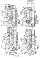
- the declutching device 2 is here formed by the ends of the radial fingers 3 of a diaphragm, which, as is known, comprises a peripheral part forming a Belleville washer, for clamping at least one friction disc between two plates, and a central part fragmented into radial fingers.
- This docking piece 4 has a flange 5 of radial orientation with a bearing surface 5 'for action on the declutching device 2 and, in one piece with it, a socket 6 which, extending generally axially, passes through the declutching device 2 through the opening 3 'thereof and at the end of which, on the side of the stopper 1, are arranged at its outer periphery elastic means, here a Bellev washer. ille 7, which constantly request the range of support 5 ′ of said docking part in the direction of the declutching device 2.
- the fingers 3 of the diaphragm are pinched between the bearing 5 ′ and the washer 7 which rests at its internal periphery on a circlip 7 'engaged in a groove made at the end of the sleeve 6.
- the sleeve 6 On the side directed towards the declutching stop 1, the sleeve 6 has, at the end of its internal bore, an engagement surface 8, here frustoconical, whose concavity is turned towards said stop.
- a cylindrical guide bearing 9, of diameter D1 follows this frustoconical bearing 8 and is connected to a bearing 10, inclined on the axis of the assembly, moving away from said axis away from the clutch release bearing 1.
- This bearing constitutes one of the sides of an annular retaining groove 11 ′, the bottom 11 of which is profiled and has an extreme diameter D3 (fig. 3).
- This groove 11 ′ is located in the connection zone between the socket 6 and collar 5.
- bottom 11 in cross section, has a generally semicircle profile conforming to that of a connection ring in traction 14 described below.
- the bottom 11 is connected to a retaining surface 12 inclined on the axis of the assembly moving away from said axis while approaching the declutching stop 1, that is to say in the opposite direction relative to the range 10, the latter being concave in the axial direction going from the declutching device to the stop 1 while the bearing 12 is convex for the same direction.
- This bearing 12 therefore forms the other side of the retaining groove 11 '.
- a stop surface 13 inclined on the axis of the assembly, deviating from said axis by approaching the clutch release bearing 1.
- Said bearing surface 13 delimits, with an internal bore 15 of the docking piece 4 and the face of the docking piece 4 turned away from the declutching device 2, a stop heel 23 of internal diameter D5.
- a rod 14 elastically deformable radially outward carried by the retaining groove 11 ', while in the free state, at a distance from the bottom 11 of the retaining groove 11' at least partially in contact with the bearing surface 12.
- the declutching stop 1 comprises an attack piece 16 for action, in particular by means of the rod 14, on the docking piece 4.
- the attack piece 16 is here constituted by the extension 17 of the inner ring of a ball bearing 18, axially coupled to an operating element shown diagrammatically in 19 on which the operating means act, for example the ends of the fingers 45 of a clutch fork.
- This operating element 19 has a sleeve 20 for sliding, for example, on a declutching trumpet surrounding the input shaft of the gearbox.
- the stop is self-centering maintained, therefore a clearance exists between the inner ring of the bearing 18 and the sleeve 20, and as described in the application FR 2 508 125 of 18.06.1981, the cover 41 is linked to the operating element 19 by means of clipping means with elastically deformable tabs belonging to said operating element 19 and with opening belonging to the cover 41, said openings forming a shoulder for said tabs.
- the wall 42 carries, in a diametrically opposite position with respect to each other, a pair of two opposite transverse bearing faces 43, 44. which, for cooperation with the ends of the fingers 45 of the clutch release fork, generally extend transversely.
- the faces 43 each belong to a lug 46 which is integral with the cover 41, extending transversely substantially in the plane of the radial flange 19 ′, which comprises the operating element 19 at its end furthest from the end of the attack piece 16.
- the faces 44 each belong to a tab 47 secured to the cover 41 extending transversely to distance from the lug 46, to allow the housing of the fingers 45 of the clutch release fork.
- the attack piece 16 is provided with a frustoconical centering surface 21, of a shape complementary to that of the inclined stop surface 13, which is extended, inclined in the opposite direction with respect to said range for centering, by a drive surface 22 directed towards the clutch release bearing 1.
- the intersection of the two surfaces forms a cylindrical zone of circular section 40 of diameter D2 at most equal to the diameter D1 of the guide surface 9 but greater than the diameter D5 of the internal bore 15 of the locking bead 23.
- This drive surface 22 forms one of the sides of a groove 24, provided annularly for this purpose on the declutching stop 1 and more precisely on the external periphery of the attack piece 16, the other of the sides 25 of this groove 24 is mounted axially movable relative to the side 22 of said groove.
- this sidewall 25 belongs to a part 26, known as a separation part, which, distinct from the leading part 16 is slidably mounted axially thereon but which, like this leading part 16, also belongs to said clutch release bearing.
- this sidewall 25 belongs to the section 27 directed towards the declutching device 2 of the separation piece 26, and constitutes the part of the section 27 closest to the axis of the assembly, oblique on said axis, moving away from said axis while approaching the declutching device.
- the outer edge or outer diameter of this oblique flank 25 has a diameter less than the median diameter of the rod 14 mounted on the attack piece 16 (fig.4) and more precisely on the bottom of the groove 24.
- the disconnection piece 26 door at its end directed towards the declutching device 2 at in the vicinity of the section 27, positioning means 29 elastically deformable radially inwards, of greater external diameter, in the free state, than the internal diameter D1 of the engagement surface 8 adapted to bear on the scope 8 in stressing, during assembly, said separation piece in the direction of a stopper 32 provided transversely for it on the declutching stop 1.
- this stopper 32 is formed by the shoulder of the inner ring of the bearing 18, the inside diameter of the engagement surface 8 corresponds to the diameter Dl of the guide scope.
- the positioning means consist of at least one lug 30 which is generally axial, here three, in one piece with the separation piece 26, which is elastically deformable radially inwards; said tabs have at their ends directed towards the declutching device, a rounded contact surface 33 and; have located axially set back relative to the edge 27 of the separation piece.
- the legs 30 are radially projecting.
- this separation piece 26 is made of synthetic material.
- the separation piece 26 has an L-shaped cross-section and has, for the action of an operating member, a radial flange 31, projecting at its periphery, arranged at the end of the separation piece 26 opposite the section 27, with an external diameter greater than that of the axial wall 42 of the cover 41.
- This radial flange 31 is provided, for its mounting on the attack piece 16, with a radial groove 34, opening radially outward, in the extension of another axial groove 35.
- this axial groove 35 extends on either side of the axial part of said separation piece 26 by connecting to the radial groove 34.
- said flange 31 has, diametrically opposite with respect to to this groove 34, a thinned sector in thickness 36, which, by its small circumferential extent and by its thinning, makes it possible to obtain additional elasticity during the opening of the grooves 34 and 35 of the separation piece 26, for mounting on the attack piece 16, for example over the edge 21 of the attack piece 16.
- a plate 37 After its mounting on the attack piece 16, a plate 37, called a wear plate, is attached to the face of said flange 31 directed towards the declutching stop 1 and is held by crimping on said face by the edges 38, 39 of said plate. More precisely, the outer edge of the plate is folded axially towards the declutching device to form the axial edge 39 and then radially towards the axis of the assembly to form the radial edge 38 by trapping the outer peripheral edge of the flange 31. From this thanks to this plate 37 the flange 31, as well as the axial part of the separation piece 26, can no longer open radially.
- the stop 1 After continuing the movement, the stop 1, thanks to the two bearing surfaces 8, 21, is pre-centered relative to the docking part 4 then, the movement continuing, the leading part 16 slides and is centered by its zone 40 along of the cylindrical guide surface 9 of the docking part 4 by driving with it the separation piece 26 and in particular the end of said separation piece directed towards the clutch release bearing 1, which penetrates under the bearing 9, until the positioning means, here the tabs 30 in the deployed position, come into contact, through their rounded edges 33, with the frustoconical surface 8 of the docking part 4.
- the detachment piece is urged, by means of the tabs 30 in contact with the bearing 8, in the direction of the declutching stop 1 and slides on the external periphery of the attack piece 16 up to in contact through its rear part with the stopper 32 provided transversely for it on the declutching stopper 1.
- the separation piece 26 is in abutment on the declutching stop at 32 and is in contact with the bearing surface 8. Therefore, the movable flank 25, is positioned in a determined manner with respect to the other of the sides, said to be fixed, of the groove 24, here the drive range 22, and to the frustoconical engagement range 8 of the docking piece 4.
- the range frustoconical centering 21 of the attack piece 16 precentre the securing means, here the rod 14.
- the vertical axis of the rod 14 leaves the zone 40 and, by its radial elasticity, returning to its initial position, slides respectively along the span 22 of the groove 24 and along the span 10 of the docking piece 4 until the rod 14 comes into contact, by its internal diameter, with the bottom of the groove 24.
- this position makes the groove 24 non-existent and prevents, in the event of undesirable manipulation, a return of the rod 14 on the bearing 22 and therefore in the groove 24 of the attack piece 16.
- (D3 - D2) / 2 must be at least equal to the thickness of the rod 14.
- the angle formed by the axis of the assembly and the drive range 22 of the attack piece 16 as well as the angle formed by the same axis and the drive range 10 of the piece d 'docking 4 are suitably sized to allow the transmission of the tensile force of the assembly.
- the invention is not limited to the embodiments described but embraces all variants in the production of its various elements and in its applications within the framework of the claims, in particular the end 33 of the legs 30 can be chamfered, and the docking part instead of being attached to the declutching device by pinching, can be attached by means of retaining fingers each carrying a lug, the flange as described in patent application FR 2 544 037 of April 11 1983.
- the decoupling member instead of being opened by a slot for its positioning on the attack piece which it must equip, may have, re regularly distributed along one and the other of its axial end sections, notches, which, circularly alternating from one to the other of these sections, are axially nested from one to the other of these.
Landscapes
- Engineering & Computer Science (AREA)
- General Engineering & Computer Science (AREA)
- Mechanical Engineering (AREA)
- Mechanical Operated Clutches (AREA)
- Packaging Of Annular Or Rod-Shaped Articles, Wearing Apparel, Cassettes, Or The Like (AREA)
Applications Claiming Priority (2)
| Application Number | Priority Date | Filing Date | Title |
|---|---|---|---|
| FR8514924A FR2588336B1 (fr) | 1985-10-09 | 1985-10-09 | Montage de butee de debrayage notamment pour vehicules automobiles |
| FR8514924 | 1985-10-09 |
Publications (2)
| Publication Number | Publication Date |
|---|---|
| EP0220982A1 true EP0220982A1 (de) | 1987-05-06 |
| EP0220982B1 EP0220982B1 (de) | 1988-12-28 |
Family
ID=9323652
Family Applications (1)
| Application Number | Title | Priority Date | Filing Date |
|---|---|---|---|
| EP86402199A Expired EP0220982B1 (de) | 1985-10-09 | 1986-10-06 | Aufstellung eines Kupplungsausrückers, insbesondere für ein Kraftfahrzeug |
Country Status (7)
| Country | Link |
|---|---|
| US (1) | US4733764A (de) |
| EP (1) | EP0220982B1 (de) |
| JP (1) | JPS62165023A (de) |
| BR (1) | BR8604912A (de) |
| DE (1) | DE3661569D1 (de) |
| ES (1) | ES2006690B3 (de) |
| FR (1) | FR2588336B1 (de) |
Cited By (3)
| Publication number | Priority date | Publication date | Assignee | Title |
|---|---|---|---|---|
| FR2680399A1 (fr) * | 1991-08-17 | 1993-02-19 | Luk Lamellen & Kupplungsbau | Systeme de debrayage pour vehicules automobiles. |
| US5445257A (en) * | 1993-01-20 | 1995-08-29 | Valeo | Declutching device having a hydraulic actuator for snap-fitting on-to a pull-off type clutch |
| EP2924309A3 (de) * | 2014-03-26 | 2016-03-02 | Schaeffler Technologies GmbH & Co. KG | Tellerfedereinrichtung mit Druckstück |
Families Citing this family (9)
| Publication number | Priority date | Publication date | Assignee | Title |
|---|---|---|---|---|
| JPS62246628A (ja) * | 1986-04-18 | 1987-10-27 | Daikin Mfg Co Ltd | クラツチのレリ−ズベアリング機構 |
| DE3632884C2 (de) * | 1986-09-27 | 1995-04-27 | Fichtel & Sachs Ag | Gezogene Membranfederkupplung mit Schnappverbindung |
| JPS63145827A (ja) * | 1986-12-08 | 1988-06-17 | Daikin Mfg Co Ltd | クラツチのレリ−ズベアリング機構 |
| JPH0728420Y2 (ja) * | 1988-07-12 | 1995-06-28 | 株式会社大金製作所 | クラッチのレリーズベアリング機構 |
| JPH077625Y2 (ja) * | 1990-05-18 | 1995-02-22 | 株式会社大金製作所 | レリーズベアリング組立体 |
| JP2566882Y2 (ja) * | 1991-03-04 | 1998-03-30 | 株式会社エクセディ | プルタイプクラッチ用レリーズ装置及びそれに用いられるスクープリング |
| US5273146A (en) * | 1991-04-09 | 1993-12-28 | Nsk Ltd. | Bearing unit for clutch release |
| JP3232720B2 (ja) * | 1992-11-27 | 2001-11-26 | アイシン精機株式会社 | クラツチレリーズベアリング組立体 |
| DE10136424C1 (de) * | 2001-07-26 | 2002-10-10 | Zf Sachs Ag | Ausrücker für eine Reibungskupplung |
Citations (3)
| Publication number | Priority date | Publication date | Assignee | Title |
|---|---|---|---|---|
| GB2062799A (en) * | 1979-11-06 | 1981-05-28 | Skf Kugellagerfabriken Gmbh | Assembly comprising a shaft removably held axially in a bore of a housing and a clutch release mechanism including such an assembly |
| DE3113463A1 (de) * | 1981-04-03 | 1982-12-30 | LuK Lamellen und Kupplungsbau GmbH, 7580 Bühl | Reibungskupplung |
| FR2518678A1 (fr) * | 1981-12-18 | 1983-06-24 | Fichtel & Sachs Ag | Dispositif d'embrayage |
Family Cites Families (11)
| Publication number | Priority date | Publication date | Assignee | Title |
|---|---|---|---|---|
| FR2304826A1 (fr) * | 1975-03-19 | 1976-10-15 | Ferodo Sa | Mecanisme de commande en rotation notamment pour vehicule automobile, et embrayage et butee de debrayage propres a la realisation d'un tel mecanisme |
| DE2639766C2 (de) * | 1976-09-03 | 1986-01-09 | LuK Lamellen und Kupplungsbau GmbH, 7580 Bühl | Reibungskupplungseinheit |
| EP0044691B1 (de) * | 1980-07-22 | 1984-09-19 | Automotive Products Public Limited Company | Zieheinrichtung zum Lösen einer Kupplung |
| DE3119367C1 (de) * | 1981-05-15 | 1982-12-09 | Bayerische Motoren Werke AG, 8000 München | Vorrichtung zum hydraulischen Betaetigen einer gezogenen Reibungskupplung fuer Kraftfahrzeuge |
| DE3375191D1 (en) * | 1982-11-19 | 1988-02-11 | Automotive Prod Plc | A friction clutch for a vehicle |
| FR2538060B1 (fr) * | 1982-12-15 | 1988-07-08 | Valeo | Montage de butee de debrayage, notamment pour vehicule automobile |
| FR2544036B1 (fr) * | 1983-04-11 | 1988-10-28 | Valeo | Piece d'accostage a rapporter sur le diaphragme d'un embrayage, et ensemble unitaire constitue par un tel diaphragme et une telle piece d'accostage |
| FR2545172B1 (fr) * | 1983-04-26 | 1986-03-21 | Valeo | Montage de butee de debrayage, piece d'accostage pour un tel montage et procedes de mise en place et de demontage du montage de butee |
| FR2557234B1 (fr) * | 1983-12-27 | 1989-03-31 | Valeo | Montage de butee de debrayage, et butee de debrayage propre a un tel montage |
| GB8404519D0 (en) * | 1984-02-21 | 1984-03-28 | Automotive Prod Plc | Friction clutch for vehicle |
| FR2580353B1 (fr) * | 1985-04-10 | 1990-07-20 | Automotive Products Plc | Mecanisme d'accouplement de butee d'embrayage pour vehicules automobiles |
-
1985
- 1985-10-09 FR FR8514924A patent/FR2588336B1/fr not_active Expired - Lifetime
-
1986
- 1986-10-06 EP EP86402199A patent/EP0220982B1/de not_active Expired
- 1986-10-06 DE DE8686402199T patent/DE3661569D1/de not_active Expired
- 1986-10-06 ES ES86402199T patent/ES2006690B3/es not_active Expired
- 1986-10-08 BR BR8604912A patent/BR8604912A/pt not_active IP Right Cessation
- 1986-10-08 US US06/916,802 patent/US4733764A/en not_active Expired - Lifetime
- 1986-10-09 JP JP61241147A patent/JPS62165023A/ja active Pending
Patent Citations (3)
| Publication number | Priority date | Publication date | Assignee | Title |
|---|---|---|---|---|
| GB2062799A (en) * | 1979-11-06 | 1981-05-28 | Skf Kugellagerfabriken Gmbh | Assembly comprising a shaft removably held axially in a bore of a housing and a clutch release mechanism including such an assembly |
| DE3113463A1 (de) * | 1981-04-03 | 1982-12-30 | LuK Lamellen und Kupplungsbau GmbH, 7580 Bühl | Reibungskupplung |
| FR2518678A1 (fr) * | 1981-12-18 | 1983-06-24 | Fichtel & Sachs Ag | Dispositif d'embrayage |
Cited By (4)
| Publication number | Priority date | Publication date | Assignee | Title |
|---|---|---|---|---|
| FR2680399A1 (fr) * | 1991-08-17 | 1993-02-19 | Luk Lamellen & Kupplungsbau | Systeme de debrayage pour vehicules automobiles. |
| ES2065226A2 (es) * | 1991-08-17 | 1995-02-01 | Luk Lamellen & Kupplungsbau | "sistema de desembrague para un embrague de friccion de "funcion por tiro" |
| US5445257A (en) * | 1993-01-20 | 1995-08-29 | Valeo | Declutching device having a hydraulic actuator for snap-fitting on-to a pull-off type clutch |
| EP2924309A3 (de) * | 2014-03-26 | 2016-03-02 | Schaeffler Technologies GmbH & Co. KG | Tellerfedereinrichtung mit Druckstück |
Also Published As
| Publication number | Publication date |
|---|---|
| JPS62165023A (ja) | 1987-07-21 |
| DE3661569D1 (en) | 1989-02-02 |
| FR2588336A1 (fr) | 1987-04-10 |
| ES2006690B3 (es) | 1989-07-16 |
| EP0220982B1 (de) | 1988-12-28 |
| US4733764A (en) | 1988-03-29 |
| FR2588336B1 (fr) | 1990-01-26 |
| BR8604912A (pt) | 1987-07-07 |
Similar Documents
| Publication | Publication Date | Title |
|---|---|---|
| FR2544429A1 (fr) | Procede pour le montage d'une butee de debrayage, et butee de debrayage correspondante, notamment pour vehicule automobile | |
| EP0220982B1 (de) | Aufstellung eines Kupplungsausrückers, insbesondere für ein Kraftfahrzeug | |
| FR2557234A1 (fr) | Montage de butee de debrayage, et butee de debrayage propre a un tel montage | |
| EP0243229B1 (de) | Zusammenbau eines Kupplungsausrücklagers, insbesondere für ein Kraftfahrzeug | |
| EP3252333B1 (de) | Axiales einrastsystem für einen kupplungsmechanismus | |
| EP3494323B1 (de) | Kompakter doppelkupplungsmechanismus und getriebesystem mit solch einem doppelkupplungsmechanismus | |
| EP0223645B1 (de) | Trennbarer Zusammenbau eines Kupplungsausrücklagers, insbesondere für Kraftfahrzeuge | |
| EP0674753B1 (de) | Kupplungseinheit wobei das gehäuse mit einer schnappverbindung auf dem schwungrad befestigt ist | |
| EP0533537B1 (de) | Ausrücklager für eine gezogene Kupplung, insbesondere für Kraftfahrzeuge | |
| FR2579703A1 (fr) | Butee de debrayage, notamment pour vehicule automobile | |
| FR2557235A1 (fr) | Montage de butee de debrayage | |
| FR2589538A1 (fr) | Montage de butee de debrayage notamment pour vehicules automobiles | |
| FR2712361A1 (fr) | Module d'embrayage à moyens de retenue radiale pour le prolongement par lequel le couvercle est assujetti au volant. | |
| FR2584788A1 (fr) | Butee de debrayage a autocentrage maintenu, avec une rondelle de serrage a elasticite radiale | |
| EP0360650A1 (de) | Kupplungsausrücklager, insbesondere für Kraftfahrzeuge | |
| EP0190970B1 (de) | Kupplungsausrücker, insbesondere für Kraftfahrzeug | |
| WO2000022314A1 (fr) | Embrayage a friction associe a un dispositif de detection d'usure | |
| EP3677808B1 (de) | Kupplungsmechanismus für kraftfahrzeug, und kupplung, die einen solchen kupplungsmechanismus umfasst | |
| FR2669980A1 (fr) | Butee de debrayage a rondelle elastique externe, notamment pour vehicules automobiles. | |
| FR2583480A1 (fr) | Montage de butee de debrayage et procedes de mise en place et de demontage du montage de butee | |
| FR2629885A1 (fr) | Montage de butee de debrayage, notamment pour vehicule automobile | |
| FR3082572A1 (fr) | Dispositif d'arret axial entre deux pieces | |
| FR2742200A1 (fr) | Montage de butee de debrayage, notamment pour vehicule automobile | |
| FR2579280A1 (fr) | Butee de debrayage, notamment pour vehicule automobile | |
| FR2584787A1 (fr) | Montage de butee de debrayage et butee de debrayage propre a un tel montage |
Legal Events
| Date | Code | Title | Description |
|---|---|---|---|
| PUAI | Public reference made under article 153(3) epc to a published international application that has entered the european phase |
Free format text: ORIGINAL CODE: 0009012 |
|
| AK | Designated contracting states |
Kind code of ref document: A1 Designated state(s): DE ES FR GB IT |
|
| 17P | Request for examination filed |
Effective date: 19870401 |
|
| 17Q | First examination report despatched |
Effective date: 19880330 |
|
| GRAA | (expected) grant |
Free format text: ORIGINAL CODE: 0009210 |
|
| AK | Designated contracting states |
Kind code of ref document: B1 Designated state(s): DE ES FR GB IT |
|
| REF | Corresponds to: |
Ref document number: 3661569 Country of ref document: DE Date of ref document: 19890202 |
|
| ITF | It: translation for a ep patent filed | ||
| GBT | Gb: translation of ep patent filed (gb section 77(6)(a)/1977) | ||
| PLBE | No opposition filed within time limit |
Free format text: ORIGINAL CODE: 0009261 |
|
| STAA | Information on the status of an ep patent application or granted ep patent |
Free format text: STATUS: NO OPPOSITION FILED WITHIN TIME LIMIT |
|
| 26N | No opposition filed | ||
| PGFP | Annual fee paid to national office [announced via postgrant information from national office to epo] |
Ref country code: GB Payment date: 19920929 Year of fee payment: 7 |
|
| PGFP | Annual fee paid to national office [announced via postgrant information from national office to epo] |
Ref country code: ES Payment date: 19921031 Year of fee payment: 7 |
|
| PG25 | Lapsed in a contracting state [announced via postgrant information from national office to epo] |
Ref country code: GB Effective date: 19931006 |
|
| PG25 | Lapsed in a contracting state [announced via postgrant information from national office to epo] |
Ref country code: ES Free format text: LAPSE BECAUSE OF THE APPLICANT RENOUNCES Effective date: 19931007 |
|
| GBPC | Gb: european patent ceased through non-payment of renewal fee |
Effective date: 19931006 |
|
| ITTA | It: last paid annual fee | ||
| REG | Reference to a national code |
Ref country code: ES Ref legal event code: FD2A Effective date: 19991007 |
|
| PGFP | Annual fee paid to national office [announced via postgrant information from national office to epo] |
Ref country code: DE Payment date: 20051007 Year of fee payment: 20 |
|
| PGFP | Annual fee paid to national office [announced via postgrant information from national office to epo] |
Ref country code: IT Payment date: 20051021 Year of fee payment: 20 |
|
| PGFP | Annual fee paid to national office [announced via postgrant information from national office to epo] |
Ref country code: FR Payment date: 20051028 Year of fee payment: 20 |