EP0221042A2 - Gaserzeuger und sein Kontrollverfahren - Google Patents
Gaserzeuger und sein Kontrollverfahren Download PDFInfo
- Publication number
- EP0221042A2 EP0221042A2 EP86870127A EP86870127A EP0221042A2 EP 0221042 A2 EP0221042 A2 EP 0221042A2 EP 86870127 A EP86870127 A EP 86870127A EP 86870127 A EP86870127 A EP 86870127A EP 0221042 A2 EP0221042 A2 EP 0221042A2
- Authority
- EP
- European Patent Office
- Prior art keywords
- gas
- chimney
- conduit
- hearth
- gasifier
- Prior art date
- Legal status (The legal status is an assumption and is not a legal conclusion. Google has not performed a legal analysis and makes no representation as to the accuracy of the status listed.)
- Withdrawn
Links
Images
Classifications
-
- C—CHEMISTRY; METALLURGY
- C10—PETROLEUM, GAS OR COKE INDUSTRIES; TECHNICAL GASES CONTAINING CARBON MONOXIDE; FUELS; LUBRICANTS; PEAT
- C10J—PRODUCTION OF PRODUCER GAS, WATER-GAS, SYNTHESIS GAS FROM SOLID CARBONACEOUS MATERIAL, OR MIXTURES CONTAINING THESE GASES; CARBURETTING AIR OR OTHER GASES
- C10J3/00—Production of combustible gases containing carbon monoxide from solid carbonaceous fuels
- C10J3/72—Other features
- C10J3/82—Gas withdrawal means
-
- C—CHEMISTRY; METALLURGY
- C10—PETROLEUM, GAS OR COKE INDUSTRIES; TECHNICAL GASES CONTAINING CARBON MONOXIDE; FUELS; LUBRICANTS; PEAT
- C10J—PRODUCTION OF PRODUCER GAS, WATER-GAS, SYNTHESIS GAS FROM SOLID CARBONACEOUS MATERIAL, OR MIXTURES CONTAINING THESE GASES; CARBURETTING AIR OR OTHER GASES
- C10J3/00—Production of combustible gases containing carbon monoxide from solid carbonaceous fuels
- C10J3/02—Fixed-bed gasification of lump fuel
- C10J3/20—Apparatus; Plants
- C10J3/22—Arrangements or dispositions of valves or flues
- C10J3/24—Arrangements or dispositions of valves or flues to permit flow of gases or vapours other than upwardly through the fuel bed
- C10J3/26—Arrangements or dispositions of valves or flues to permit flow of gases or vapours other than upwardly through the fuel bed downwardly
-
- C—CHEMISTRY; METALLURGY
- C10—PETROLEUM, GAS OR COKE INDUSTRIES; TECHNICAL GASES CONTAINING CARBON MONOXIDE; FUELS; LUBRICANTS; PEAT
- C10J—PRODUCTION OF PRODUCER GAS, WATER-GAS, SYNTHESIS GAS FROM SOLID CARBONACEOUS MATERIAL, OR MIXTURES CONTAINING THESE GASES; CARBURETTING AIR OR OTHER GASES
- C10J3/00—Production of combustible gases containing carbon monoxide from solid carbonaceous fuels
- C10J3/72—Other features
- C10J3/723—Controlling or regulating the gasification process
-
- C—CHEMISTRY; METALLURGY
- C10—PETROLEUM, GAS OR COKE INDUSTRIES; TECHNICAL GASES CONTAINING CARBON MONOXIDE; FUELS; LUBRICANTS; PEAT
- C10J—PRODUCTION OF PRODUCER GAS, WATER-GAS, SYNTHESIS GAS FROM SOLID CARBONACEOUS MATERIAL, OR MIXTURES CONTAINING THESE GASES; CARBURETTING AIR OR OTHER GASES
- C10J3/00—Production of combustible gases containing carbon monoxide from solid carbonaceous fuels
- C10J3/72—Other features
- C10J3/82—Gas withdrawal means
- C10J3/84—Gas withdrawal means with means for removing dust or tar from the gas
-
- C—CHEMISTRY; METALLURGY
- C10—PETROLEUM, GAS OR COKE INDUSTRIES; TECHNICAL GASES CONTAINING CARBON MONOXIDE; FUELS; LUBRICANTS; PEAT
- C10J—PRODUCTION OF PRODUCER GAS, WATER-GAS, SYNTHESIS GAS FROM SOLID CARBONACEOUS MATERIAL, OR MIXTURES CONTAINING THESE GASES; CARBURETTING AIR OR OTHER GASES
- C10J2200/00—Details of gasification apparatus
- C10J2200/36—Moving parts inside the gasification reactor not otherwise provided for
-
- C—CHEMISTRY; METALLURGY
- C10—PETROLEUM, GAS OR COKE INDUSTRIES; TECHNICAL GASES CONTAINING CARBON MONOXIDE; FUELS; LUBRICANTS; PEAT
- C10J—PRODUCTION OF PRODUCER GAS, WATER-GAS, SYNTHESIS GAS FROM SOLID CARBONACEOUS MATERIAL, OR MIXTURES CONTAINING THESE GASES; CARBURETTING AIR OR OTHER GASES
- C10J2300/00—Details of gasification processes
- C10J2300/09—Details of the feed, e.g. feeding of spent catalyst, inert gas or halogens
- C10J2300/0913—Carbonaceous raw material
- C10J2300/0946—Waste, e.g. MSW, tires, glass, tar sand, peat, paper, lignite, oil shale
-
- C—CHEMISTRY; METALLURGY
- C10—PETROLEUM, GAS OR COKE INDUSTRIES; TECHNICAL GASES CONTAINING CARBON MONOXIDE; FUELS; LUBRICANTS; PEAT
- C10J—PRODUCTION OF PRODUCER GAS, WATER-GAS, SYNTHESIS GAS FROM SOLID CARBONACEOUS MATERIAL, OR MIXTURES CONTAINING THESE GASES; CARBURETTING AIR OR OTHER GASES
- C10J2300/00—Details of gasification processes
- C10J2300/09—Details of the feed, e.g. feeding of spent catalyst, inert gas or halogens
- C10J2300/0953—Gasifying agents
- C10J2300/0956—Air or oxygen enriched air
Definitions
- the present invention relates to improvements to the apparatuses used for the production of a combustible gas which can be used in different applications.
- a combustible gas which can be used in different applications.
- these applications there may be mentioned the supply of stationary engines, for example actuating generators or pumps and the supply of engines mounted on vehicles, such as trucks or tractors; the gas can also be used for the production of heat in gas burners.
- gas generators - or gas generators - has been well known for a long time; the fuels used are various: charcoal, peat, lignite, coal (preferably lean coal), but also vegetable waste such as coffee leaves, bagasse, etc.
- the gas obtained is normally the product of a incomplete combustion of carbon in an air stream passing through a thick layer of fuel; this gas - called gas in air - contains mainly nitrogen and carbon monoxide, and incidentally of the year carbon dioxide, hydrogen, methane and possibly a small amount of ethane.
- Conventional gas generators basically consist of a fuel hopper-store closed at the bottom by a grid, a system for introducing combustion air into the gas generator - possibly by suction - and a system for treating the gas obtained complete the installation.
- the present invention relates to improvements in gas generating devices and its main object is a gas production system freed of its impurities by treatment of the gas produced.
- the gas circulates in a chimney disposed inside the generation enclosure, chimney composed of two substantially coaxial conduits, between which is provided a space for the circulation of gas; the lower orifice of the external duct is open to let the gas captured in the extraction zone under the hearth, while the upper end of said external duct is closed; the upper end of the internal conduit, located at a certain distance under the closed upper end of the external conduit, is open to allow the passage of gas from the external conduit into the internal conduit; for its part, the lower part of said internal duct is connected to the means for supplying, for example, the engine, possibly via a purification system - wet or dry - of the gas produced.
- the gas captured in the extraction zone under the hearth, where the separation of the gaseous products and the solid residues takes place which gas is at a temperature for example of 600 ° C. and also has a share of CO 2 , is forced to go up in the chimney formed between the two coaxial conduits to be reheated to more than 1000 ° C at the top (closed) of the chimney; given this very high temperature, CO 2 in particular will transform into C0, at the same time as various cracking of hydrocarbons and undesirable elements will take place; the gas thus improved is then sucked into the internal conduit where it descends to gain the output of the generator.
- the gas generator which includes the improvements described in one and / or the other of the aforementioned patents, already allows the production of a validly purified gas.
- the first object of the present invention is an improvement to the gas production device which has just been mentioned and it provides an almost definitive solution to the problem of manufacturing a clean combustible gas with gasifier.
- the gasifier, object of the present invention which is equipped with a chimney disposed inside the gas generation enclosure and composed of two coaxial conduits, ensuring the capture of the gas at the bottom of the enclosure and the circulation of the gas first from bottom to top, through the external pipe, up to the level of the combustion zone and then from top to bottom through the internal pipe up to the gas outlet pipe, is characterized in that that it comprises an elongated metal element integral with the cover closing the upper part of the external conduit and passing through said cover, and in that this elongate element plunges inside the internal conduit of the chimney, coaxial with this conduit.
- the part of the elongated metal element which exceeds said cover is thus in direct contact with the combustion zone in the hearth and carries at high temperature the part plunging into the internal duct and along which the gas.
- the gas descending in the internal conduit of the exhaust chimney circulates for a significant time, along a metallic element at very high temperature, which ensures the ideal transformation of CO 2 into CO and eliminates, by cracking, the last impurities, and in particular tar, which could still be in the gas at this place.
- the elongated element disposed in the internal conduit has a cruciform section; according to a particularly advantageous embodiment of this embodiment, when the internal duct is of square cross section, the ends of the cross are housed in the corners of the square, which ensures a maximum contact surface between the gas and the walls of the wings of the 'elongated element.
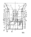
- FIG. 1 which shows a vertical section of the gas generation zone concerned by the invention
- the enclosure (4) (5) (12) constitutes a hermetically sealed assembly, in particular because of the door (25) blocking access to the ashtray; this door is removable to allow removal of ashes.
- the gas produced is thus forced to flow through the chimney located inside the gas generation enclosure and constituted by two coaxial conduits, one of which says external (8) is closed at the top by a cover ( 14), and of which the other said internal (9) is connected at its base to the pipe (11) for output from the enclosure (4) (5) of gas generation.
- Inside the internal conduit (9) is arranged a metallic element (13); the upper end of this element exceeds the level of the cover (14) closing the external conduit (8).
- the arrows appearing in the drawing show diagrammatically the path followed by the gas passing through the device of the invention.
- the gases enter the space between the external (8) and internal (9) conduits; at the top of the chimney, the upward path of the gas is interrupted due to the presence of the shutter device (14) of the external duct (8) and the gas descends from the inside (10) of the internal conduit to reach the evacuation pipe (11).
- the gas On leaving the enclosure (4) (5) for generating the gas, the gas is entrained in the space (18) between the wall (15) of the hearth and the external wall (16) of the generator; it is thus forced to circulate again upward towards the high temperature zone close to the nozzles (2) (3) thus maintaining an optimum temperature for the conversion of Co 2 to CO in the zone (4) (5); the gas finally reaches the extraction pipe (17) and the pipes leading either to the other possible means of purification, or directly to the gas utilization devices (engine, etc.). In the space (12) there are means (not shown) for evacuating solid residues.
- the outer conduit (8) On its inner wall, the outer conduit (8) is here provided with oblique baffles (19) which have the effect of rotating the gas stream and projecting it against the upper part of the element at high temperature (13) where harmful residues are practically all burned; the balance is eliminated during the descent of the gas along said element (13).
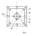
- Figure 2 shows a cross section of the gas generation device, located at the nozzles (2), (3); there are the external (8) and internal (9) conduits, the elongated cruciform element (13) as well as the wall (15) of the hearth and the external wall (16) of the gas generator between which the gas extracted from the generation enclosure before being evacuated from the generator.
- the chimney and the gas generation enclosure are both of square section and are arranged with their respective sides making with each other angles of 45 degrees.
- the gas generation zone is in fact made up of four parallel zones A, B, C, D in the four corners of the enclosure and each delimited by one of the walls of the external duct (9) and the two half walls of the inner face (15) which face it.
- a second object of the present invention consists of a device making it possible to use the gas circulation chimney inside the fireplace for the purpose of regulating the operation of the gasifier, so that this chimney contributes to the production at the same time of a clean gas and a stable flow rate.
- the external flue of the chimney is subject, by mechanical means, to the grid control device used to maintain the charge and extract the solid residues therefrom; the movement imparted to the grid, in particular to break up any bottom clinkers and ashes, is converted into an alternating movement of ascent and descent and transmitted via the external conduit to the upper part of the elongated element integral with this conduit; the shocks due to this movement have the result of preventing the formation of an anchor or arch in the hearth and the hopper; by doing so, important causes of pressure drop modifications are eliminated in the gas generation system.
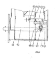
- FIG. 3 shows a system for controlling the movement of vertical translation of the external duct (8) of the chimney and of the elongated element which is secured thereto, to the movement of horizontal translation of the grid (6) controlled by a lever (21); this control is achieved by a connecting rod (20), one end of which is connected by an articulation (29) to an element (26) integral with the control lever (21) and disposed above the pivot shaft (28) of the lever (21) and the other end of which is connected to the end of a lever (22), the second end of which is fixed to a device (23) for supporting the external conduit (8); this lever (22) can tilt around the pivot (27).
- the gasifier produced according to the invention has a weakness in that its proper functioning requires monitoring and possibly human intervention; indeed, the continuous and stable production of a gas of constant quality requires periodic control by the operators and their intervention in the event that either an irregularity in the depression prevailing in the generator or in the supply of the hopper is detected. solid fuel.
- Another subject of the present invention is a method for controlling the progress of the gasifier and for optimizing the yield and efficiency of the appliance.
- the control method which is the subject of the invention is essentially characterized in that the value of at least one parameter characteristic of the progress of the gasifier is continuously monitored, for example the depression prevailing at a point in the gas circuit, after leaving the generation enclosure, or the gas temperature, in that this or these value (s) are compared with a preset preset value and in that the measurements are taken to correct the deviations observed with respect to the setpoint value (s), for example in shaking the load, to restore normal vacuum, or stopping combustion in the fireplace if the temperature becomes exaggerated.
- the present invention also relates to means for optimizing, in a simple manner, the running of the gasifier and thus ensuring the maximum yield and efficiency of the improvements to the equipment which have just been described.
- the gasifier is equipped with means for controlling the value of the vacuum prevailing in the gas generation enclosure; preferentially, the gasifier is also equipped with means for comparing this value with a preset preset value and with an automatic depression correction system; in this way, the generator can work at constant vacuum.
- the means consist of a conventional vacuum device arranged in the gas flow circuit between the outlet of the gas generator and the inlet in the user vehicles, and in a pneumatic cylinder with double effect controlling the starting of the horizontal oscillation movement of the oscillation grid and vertical of the chimney, the place where the vacuum is monitored and the cylinder being connected by a pipe, and a valve calibrated according to a preset setpoint triggering the action of the actuator and therefore of the grid in the event of a difference between the actual vacuum and the setpoint.
- the gas generator is equipped with means for monitoring the temperature of the hearth, for example by measuring the temperature of the gases at the outlet of the generator, gas temperature directly in relation to that of the hearth thanks to the presence of the element elongated plunging into the duct which precedes the exit of the gases from the generator.
- monitoring the temperature of the hearth for example by measuring the temperature of the gases at the outlet of the generator, gas temperature directly in relation to that of the hearth thanks to the presence of the element elongated plunging into the duct which precedes the exit of the gases from the generator.
- the temperature detector is a thermocouple located in the gas outlet pipe (17); the value measured by this thermocouple is compared with a set value and the gasifier is equipped with automatic means for cutting off the air supply or the gas outlet, controlled by the temperature detector; this automatism obviously does not exclude that other warning devices, such as siren etc ..., be activated to warn the operators.
Landscapes
- Chemical & Material Sciences (AREA)
- Engineering & Computer Science (AREA)
- Combustion & Propulsion (AREA)
- Oil, Petroleum & Natural Gas (AREA)
- Organic Chemistry (AREA)
- Feeding And Controlling Fuel (AREA)
- Incineration Of Waste (AREA)
Applications Claiming Priority (2)
| Application Number | Priority Date | Filing Date | Title |
|---|---|---|---|
| BE1011336 | 1985-09-20 | ||
| BE1011336 | 1985-09-20 |
Publications (2)
| Publication Number | Publication Date |
|---|---|
| EP0221042A2 true EP0221042A2 (de) | 1987-05-06 |
| EP0221042A3 EP0221042A3 (de) | 1987-07-29 |
Family
ID=3862985
Family Applications (1)
| Application Number | Title | Priority Date | Filing Date |
|---|---|---|---|
| EP86870127A Withdrawn EP0221042A3 (de) | 1985-09-20 | 1986-09-12 | Gaserzeuger und sein Kontrollverfahren |
Country Status (1)
| Country | Link |
|---|---|
| EP (1) | EP0221042A3 (de) |
Family Cites Families (4)
| Publication number | Priority date | Publication date | Assignee | Title |
|---|---|---|---|---|
| FR964798A (de) * | 1950-08-24 | |||
| DE272931C (de) * | ||||
| US3746521A (en) * | 1971-03-15 | 1973-07-17 | E Giddings | Gasification method and apparatus |
| SE8300862D0 (sv) * | 1983-02-16 | 1983-02-16 | Olle Tornegard | Gasugn i form av s k forugn till befintliga vermepannor for fastbrensle |
-
1986
- 1986-09-12 EP EP86870127A patent/EP0221042A3/de not_active Withdrawn
Also Published As
| Publication number | Publication date |
|---|---|
| EP0221042A3 (de) | 1987-07-29 |
Similar Documents
| Publication | Publication Date | Title |
|---|---|---|
| CH621571A5 (de) | ||
| EP0084492A2 (de) | Ofen und Verfahren zur Behandlung von festen Brennstoffpartikeln in einem Wirbelbett | |
| FR2985265A1 (fr) | Procede et equipement de gazeification en lit fixe | |
| JP5199204B2 (ja) | 発熱装置及び植物の栽培空間の殺虫装置 | |
| EP3475395B1 (de) | Pyrovergasungsgerät und verfahren | |
| EP0045256A2 (de) | Verfahren und Vorrichtung zum Vergasen von Pflanzenmaterialien | |
| FR2606420A1 (fr) | Procede de carbonisation de bois et fours jumeles pour la mise en oeuvre du procede | |
| FR2907881A1 (fr) | Bruleur pour chaudiere a combustibles solides du type biomasse,pneu ainsi qu'une chaudiere comportant un tel bruleur | |
| BE903268A (fr) | Gazogene perfectionne et son procede de controle | |
| EP0011037A1 (de) | Vergasungsverfahren und Vergasungsvorrichtung | |
| EP3960837A1 (de) | Festbett-pyrovergasungsreaktor mit verbessertem leistungsgrad | |
| EP2723832A1 (de) | Vergaser für festen kohlenstoffbrennstoff | |
| WO2006053869A1 (fr) | Procede de gazeification de matieres carbonees et dispositif pour sa mise en oeuvre | |
| EP3173459A1 (de) | Reaktor für die schnellpyrolyse von organischen biomasseteilchen mit injektion von heissen gasen gegen den strom | |
| EP0078068A2 (de) | Gaserzeuger | |
| CN218710205U (zh) | 一种生物质气化炉 | |
| FR2784742A1 (fr) | Procede de traitement thermique de solides divises, et dispositif de mise en oeuvre dudit procede | |
| CA2845883A1 (fr) | Gazeifieur de combustible solide carbone | |
| WO2008125460A1 (fr) | Procedes et dispositifs de fabrication de charbon de bois ameliores | |
| FR2511028A1 (fr) | Procede et installation pour la gazeification de matieres carbonees | |
| FR2566099A1 (fr) | Four d'incineration de dechets menagers et industriels | |
| FR2733031A1 (fr) | Incinerateur d'ordures menageres et autres combustibles solides | |
| FR3046454A1 (fr) | Installation de production et de traitement de fumees | |
| EP0119183A2 (de) | Gaserzeuger | |
| FR2517413A1 (fr) | Generateur de chaleur fonctionnant avec un combustible particulaire |
Legal Events
| Date | Code | Title | Description |
|---|---|---|---|
| PUAI | Public reference made under article 153(3) epc to a published international application that has entered the european phase |
Free format text: ORIGINAL CODE: 0009012 |
|
| AK | Designated contracting states |
Kind code of ref document: A2 Designated state(s): DE FR GB IT |
|
| PUAL | Search report despatched |
Free format text: ORIGINAL CODE: 0009013 |
|
| AK | Designated contracting states |
Kind code of ref document: A3 Designated state(s): DE FR GB IT |
|
| STAA | Information on the status of an ep patent application or granted ep patent |
Free format text: STATUS: THE APPLICATION IS DEEMED TO BE WITHDRAWN |
|
| 18D | Application deemed to be withdrawn |
Effective date: 19880201 |