EP0222092A2 - Armature pour un battant coulissant d'une fenêtre, porte ou des choses pareilles - Google Patents
Armature pour un battant coulissant d'une fenêtre, porte ou des choses pareilles Download PDFInfo
- Publication number
- EP0222092A2 EP0222092A2 EP86112108A EP86112108A EP0222092A2 EP 0222092 A2 EP0222092 A2 EP 0222092A2 EP 86112108 A EP86112108 A EP 86112108A EP 86112108 A EP86112108 A EP 86112108A EP 0222092 A2 EP0222092 A2 EP 0222092A2
- Authority
- EP
- European Patent Office
- Prior art keywords
- housing
- sliding
- faceplate
- wing
- gear
- Prior art date
- Legal status (The legal status is an assumption and is not a legal conclusion. Google has not performed a legal analysis and makes no representation as to the accuracy of the status listed.)
- Granted
Links
Images



Classifications
-
- E—FIXED CONSTRUCTIONS
- E05—LOCKS; KEYS; WINDOW OR DOOR FITTINGS; SAFES
- E05D—HINGES OR SUSPENSION DEVICES FOR DOORS, WINDOWS OR WINGS
- E05D15/00—Suspension arrangements for wings
- E05D15/06—Suspension arrangements for wings for wings sliding horizontally more or less in their own plane
- E05D15/10—Suspension arrangements for wings for wings sliding horizontally more or less in their own plane movable out of one plane into a second parallel plane
- E05D15/1005—Suspension arrangements for wings for wings sliding horizontally more or less in their own plane movable out of one plane into a second parallel plane the wing being supported on arms movable in horizontal planes
- E05D15/1013—Suspension arrangements for wings for wings sliding horizontally more or less in their own plane movable out of one plane into a second parallel plane the wing being supported on arms movable in horizontal planes specially adapted for windows
-
- E—FIXED CONSTRUCTIONS
- E05—LOCKS; KEYS; WINDOW OR DOOR FITTINGS; SAFES
- E05D—HINGES OR SUSPENSION DEVICES FOR DOORS, WINDOWS OR WINGS
- E05D15/00—Suspension arrangements for wings
- E05D15/06—Suspension arrangements for wings for wings sliding horizontally more or less in their own plane
- E05D15/10—Suspension arrangements for wings for wings sliding horizontally more or less in their own plane movable out of one plane into a second parallel plane
- E05D2015/1028—Suspension arrangements for wings for wings sliding horizontally more or less in their own plane movable out of one plane into a second parallel plane with only the wing moving transversely
- E05D2015/1031—Suspension arrangements for wings for wings sliding horizontally more or less in their own plane movable out of one plane into a second parallel plane with only the wing moving transversely the wing supported on arms extending from the carriage
-
- E—FIXED CONSTRUCTIONS
- E05—LOCKS; KEYS; WINDOW OR DOOR FITTINGS; SAFES
- E05Y—INDEXING SCHEME ASSOCIATED WITH SUBCLASSES E05D AND E05F, RELATING TO CONSTRUCTION ELEMENTS, ELECTRIC CONTROL, POWER SUPPLY, POWER SIGNAL OR TRANSMISSION, USER INTERFACES, MOUNTING OR COUPLING, DETAILS, ACCESSORIES, AUXILIARY OPERATIONS NOT OTHERWISE PROVIDED FOR, APPLICATION THEREOF
- E05Y2900/00—Application of doors, windows, wings or fittings thereof
- E05Y2900/10—Application of doors, windows, wings or fittings thereof for buildings or parts thereof
- E05Y2900/13—Type of wing
- E05Y2900/148—Windows
Definitions
- the invention relates to a fitting for a sliding leaf designed in the form of a window, door or the like, which is carried by two carriages guided in frame-side longitudinal rails, each of which has a support arm which can be pivoted transversely to the rail direction and which can be actuated by means of the leaf operating lever with interposition from connecting rods that run under cuff rails in a rebate-side groove of the sliding sash frame and extend from the bearing point of the sash control lever to a branch gear coupled to the support arm.
- the object of the invention is based on the task of designing a fitting of the type required in a technically simple manner in such a way that dimensional tolerances which result when the fitting is installed do not lead to any inhibitions which complicate the operation of the operating lever.
- the housing bearing the branch gear nut is longitudinally displaceable on the connecting rod faceplate arranged and fixed in its working position from the drive axis leading transversely to the displaceability.
- the output shaft protrudes from a reduction gear housing, which in turn is adjustable in the direction of displacement of the drive rod to a sliding wing support shoe, which is angular in cross-section and in the angular space of which the sliding wing frame corner is embedded in a form-fitting manner.
- the sliding sash frame corner thus forms the reference dimension by determining the position of the sliding sash carrying shoe.
- the sliding-wing carrying shoe adjustable carries the reduction gear housing. This adjustability is necessary in order to make adjustments.
- the output axis protruding from the reduction gear housing can then engage the nut in order to move the branch transmission if necessary.
- the branch drive housing consists of two opposing and in the longitudinal center plane there are interconnected housing half-parts, which support the nut between them and clamp around a narrowed section of the faceplate, which section is longer than the length of the branch gear housing.
- the branch gear housing can be produced inexpensively and simply assigned to the faceplate. After connecting the housing half-parts, the positive connection to the narrowed section of the faceplate is created.
- the dimensional difference between this narrowed section of the faceplate and the length of the branch gear determines the path by which the branch gear housing or the nut can be displaced in order to be able to accommodate the branch gear axis without jamming.
- the two housing halves are of identical shape to one another. By appropriately placing them against one another, they form the branch gear housing, which then only has to be connected, preferably by riveting.
- the numeral 1 denotes a fixed frame. It is composed of the two vertically standing frame legs 2, 3 and the horizontal frame legs 4, 5, which are interconnected in the middle by a further vertical frame leg 6. In this way it is possible to assign a fixed door leaf 7 to the fixed frame 1 on the left-hand side and a sliding leaf 8 on the right-hand side. The latter can be parked parallel to itself from its closed position and the position covering the door leaf 7 can be pushed.
- the sliding sash 8 has an operating lever 9 on its vertical frame leg 2 on the right this the closed position of the sliding sash 8. If the operating lever 9 is pivoted by 90 ° in the clockwise direction, the lower horizontal frame leg of the sliding sash 8 remains in contact position, while the opening scissors 10 provided on the upper frame leg 5 pivot and guide the sliding sash 8 into the tilted position. A further displacement of the operating lever 9 then leads to the sliding sash being turned parallel to itself. Then the sliding sash can be displaced by means of the longitudinal rails 11, 12 fastened to the horizontal frame legs 4, 5.
- Each carriage 13, 14 assigned to the sliding sash 8 is guided on the longitudinal rail 12 fastened to the lower frame leg 4 of the fixed frame 1.
- Each carriage 13, 14 is composed of two carriage parts 15, 16.
- the shorter carriage part 15 carries a guide roller 17, while the other, longer designed carriage part 16 receives two guide rollers 18.
- the shorter carriage part 15 interacts with a stop device 21 which is attached to the end of the longitudinal rail 12 and which makes it possible to hold the carriage 13 in a latching manner.
- a shorter dovetail-shaped rail 23 extends from the shorter wagon part 15, which enters into a dovetail-shaped groove 24 of the other wagon part 16 in a form-fitting manner.
- the longer carriage part 16 supports a support arm 26 around a vertically directed pin 25.
- a link 28 engages on a joint pin 27 provided in the central region of the support arm 26 and can be pivoted about a joint pin 29 of the shorter carriage part 15.
- There are lever arms such that when the support arm 26 is pivoted, the support pin 30 provided at the free end thereof and projecting upward moves on a straight line which is perpendicular to the plane of the sliding leaf.
- the longer carriage part 16 is also moved in the direction of the shorter carriage part 15, which movement is limited by the mutually facing end faces of the carriage parts 15, 16, see FIG. 3.
- the sliding sash support shoe 32, 33 is angular in cross-section and receives the sliding sash frame corner in a form-fitting manner.
- the shorter angle leg W represents the stop for the impact leg A of the sliding leaf 8.
- the sleeves 31 form an external thread which engages in an internal thread of the support shoes 32, 33, for which purpose the support shoe is also designed to be angular in view.
- Each support shoe 32, 33 is equipped with a reduction gear 34, 35. These are arranged in mirror image to one another and differ in that the reduction gear 35 assigned to the left corner of the sliding sash 8 additionally has a reversing gear 36.
- Each reduction gear 34, 35 has a gear housing 37 attached to the support shoe, which is attached to the horizontal leg 32 ', 33' by means of a screw 74 which passes through a longitudinal slot 75 of the gear housing 37. In this way it is possible to adjust the gear housing 37 to the support shoe 32, 33.
- Above the reduction gear housing 37 is an output shaft 39 which extends into the sliding sash and engages in a form-fitting manner in a nut N of a branch gear 41 meshing with the drive rod 40.
- On the output axis 39 there is an output gear consisting of two ring gears 44 and 45 and also a control cam 46 which interacts with a locking rod 49. The same is equipped with two pins 50, 51 in the area of the control cam 46.
- the locking bar 49 receives a slide 52 which forms a pocket 53 which is open on one side. The latter overlaps one of the last in the closed position of the sliding leaf 8 Reduction gear 54 outgoing blocking pin 55.
- a compression spring 56 which acts against the slide 52, loads the locking bar 49 in the direction of its locking engagement.
- the two toothed rings 44, 45 which are in free movement with respect to one another, mesh with the one reduction gear 35 with the direction reversing gear 36. This is in meshing engagement with a further reduction gear 57, which meshes with the last reduction gear 54.
- the gear 57 In the reduction gear 35, the gear 57 is lowered. Its axis then lies below the locking bar 49.
- the axis of the gear 57 is arranged higher and is approximately aligned with the center line of the locking bar 49.
- the last reduction gear 54 is rotatably connected to a bevel gear 58 which meshes with a bevel gear 59.
- the latter sits in a rotationally fixed manner on the axis 60 of a control arm 61, which axis passes through the underside of the transmission housing, protrudes over it and carries the control arm 61 there.
- the control arm 61 receives a downwardly projecting pivot pin 62, which supports a spring-loaded double lever 63 there.
- a slide 70 is guided, which engages by means of a cross pin 72 on the longer car part 16.
- the spring loading of the double lever 63 is such that the control arm is spring-loaded in the direction of its position. This is particularly necessary when the tilt position is brought about, so that a tightening torque is then exerted on the sliding sash in the direction of the fixed frame.
- the gear housings 34, 35 are overlaid by a clipped on cover rail 73.
- the sliding sash frame forms a circumferential, groove 76 on the rebate side, which is covered by a faceplate 77.
- corner deflections are provided to implement a vertical displacement of the drive rod in a horizontal movement.
- the lower, horizontally running section of the drive rod 40 actuates the branch gear 41, which is embedded in the sliding sash frame at a corresponding point.
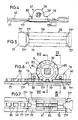
- Its housing 78 is arranged on the faceplate 77 to be longitudinally displaceable. It is made up of two opposing one another in the longitudinal center plane and of identical shape to one another.
- a connecting pin 80 extends from each housing half-part 79, which engages in a bore 81 of the other housing half-part and is riveted there at the end. Both housing half-parts leave between them a space with a rectangular cross section for the positive reception of the drive rod 40 and the faceplate 77 overlapping it, which forms a narrowed section 77 '. The width then corresponds to that of the drive rod 40.
- the narrowed section 77 'of the faceplate 77 is longer than the length of the output housing 78.
- the difference in size between the narrowed section 77' and the length of the housing determines the possible displacement path of the housing 78 to the faceplate 77.
- the narrowed section 77 ′ forms steps 77 ′′ on the faceplate 77, which limit the displacement movement of the housing 78.
- the narrowed section 77 'of the faceplate is completely covered by corresponding webs 79' of the housing half-parts 79.
- the narrowed section 77 ' is made thinner than the rest of the faceplate, see in particular FIGS. 6 and 10.
- the housing half-parts 79 support the collars 83 of the nut N, which protrude on both sides, in circular recesses 82 Center ring 84 teeth 85, which interact with tooth gaps 86 of the drive rod.
- a displacement of the drive rod 40 accordingly leads to a rotation of the nut N, which rotary movement is transmitted via the output shaft 39 provided at the end with a square section 39 '.
- This branch transmission is fixed in relation to the support shoe 32, 33. Tolerances that arise during installation can then result in a displacement of the gear housing 37 to the support shoe being necessary, so that the position of the output axis 39 deviates from the position of the nut N of the branch transmission 41. Then the output shaft engaging in the nut N leads to a displacement of the branch drive housing 78 on the narrowed section 77 'of the faceplate 77, see FIGS. 10 and 11. Accordingly, clamping forces cannot occur, and the ease of use of the fitting is thereby ensured .
- the operating lever 9 is to be pivoted through 90 ° from its initial position.
- the stay scissors 10 are pivoted over the drive rod 40 so that a spreading of the upper end of the sliding sash occurs to the fixed frame leg there.
- the lower end of the sliding sash remains in contact with the lower fixed frame leg.
- the axis 39 was also rotated by 90 ° from the nut N of the branching gear 41 without starting the reduction gear.
- the operating lever 9 must be pivoted further in the opening direction. After a small pivoting angle has been covered, the locking bar 49 is displaced via the pin 50, which comes out of engagement with the blocking pin 55, cf. FIG. 3. Now, with a further rotational movement the axis by driving rod displacement via the two sprockets 44, 45 representing the drive wheel, the reversing gear 36 in the reduction gear 35, while the other reduction gear 34 engages directly in the gear 57.
- This gearwheel 57 causes a rotation of the last reduction gearwheel 54, which rotates the axis 60 of the control lever 61 via the bevel gear transmission and thus also this, which enters a spreading position and thereby leads to a spreading of the sliding leaf 8 via the double lever 63 with a displacement of the carriage part 16 and pivoting of the support arm 26.
- This movement is limited when the end faces of both carriage parts 15, 16 face each other.
- the axis 39 has rotated approximately 180 °, which also corresponds to the entire angle of rotation of the operating lever 9. Now the sliding sash 8 can be moved in the opening direction, the latching connection between the shorter carriage part 15 and the stop device 21 being canceled.
Landscapes
- Engineering & Computer Science (AREA)
- Mechanical Engineering (AREA)
- Power-Operated Mechanisms For Wings (AREA)
- Wing Frames And Configurations (AREA)
- Support Devices For Sliding Doors (AREA)
- Specific Sealing Or Ventilating Devices For Doors And Windows (AREA)
Priority Applications (1)
| Application Number | Priority Date | Filing Date | Title |
|---|---|---|---|
| AT86112108T ATE51055T1 (de) | 1985-11-14 | 1986-09-01 | Beschlag fuer einen in form eines fensters, tuere oder dergleichen ausgebildeten schiebefluegel. |
Applications Claiming Priority (2)
| Application Number | Priority Date | Filing Date | Title |
|---|---|---|---|
| DE3540345 | 1985-11-14 | ||
| DE3540345A DE3540345C1 (de) | 1985-11-14 | 1985-11-14 | Beschlag fuer einen in Form eines Fensters,einer Tuere oder dergleichen ausgebildeten Schiebefluegel |
Publications (3)
| Publication Number | Publication Date |
|---|---|
| EP0222092A2 true EP0222092A2 (fr) | 1987-05-20 |
| EP0222092A3 EP0222092A3 (en) | 1987-09-02 |
| EP0222092B1 EP0222092B1 (fr) | 1990-03-14 |
Family
ID=6285937
Family Applications (1)
| Application Number | Title | Priority Date | Filing Date |
|---|---|---|---|
| EP86112108A Expired - Lifetime EP0222092B1 (fr) | 1985-11-14 | 1986-09-01 | Armature pour un battant coulissant d'une fenêtre, porte ou des choses pareilles |
Country Status (3)
| Country | Link |
|---|---|
| EP (1) | EP0222092B1 (fr) |
| AT (1) | ATE51055T1 (fr) |
| DE (2) | DE3540345C1 (fr) |
Cited By (2)
| Publication number | Priority date | Publication date | Assignee | Title |
|---|---|---|---|---|
| FR2810068A1 (fr) | 2000-05-31 | 2001-12-14 | Ser Lee Neo | Construction de fenetre"double fonctions de pivoter ou de coulisser" |
| WO2012077091A1 (fr) * | 2010-12-11 | 2012-06-14 | Hautau Gmbh | Ferrure facile d'utilisation pour ouvrant à déplacement parallèle |
Family Cites Families (5)
| Publication number | Priority date | Publication date | Assignee | Title |
|---|---|---|---|---|
| DE7414266U (de) * | 1975-07-03 | Glos G | Schiebeflügel | |
| DE1947523C3 (de) * | 1969-09-19 | 1983-02-03 | Wilh. Frank Gmbh, 7022 Leinfelden-Echterdingen | Treibstangenverschluß, insbesondere im Falz eines Flügels eines Fensters, einer Tür o.dgl. anzuordnendes Kantengetriebe |
| DE2344971B2 (de) * | 1973-09-06 | 1980-05-08 | Siegenia-Frank Kg, 5900 Siegen | Treibstangenbeschlag für Fenster, Türen o.dgl |
| DE8226363U1 (de) * | 1982-09-18 | 1985-05-15 | Gretsch-Unitas GmbH Baubeschläge, 7257 Ditzingen | Beschlag für einen zumindest parallelabstellbaren Flügel eines Fensters, einer Tür od. dgl. |
| DE3234677C2 (de) * | 1982-09-18 | 1986-10-23 | Gretsch-Unitas GmbH Baubeschläge, 7257 Ditzingen | Beschlag für einen zumindest parallelabstellbaren Flügel eines Fensters, einer Tür od. dgl. |
-
1985
- 1985-11-14 DE DE3540345A patent/DE3540345C1/de not_active Expired
-
1986
- 1986-09-01 EP EP86112108A patent/EP0222092B1/fr not_active Expired - Lifetime
- 1986-09-01 DE DE8686112108T patent/DE3669557D1/de not_active Expired - Lifetime
- 1986-09-01 AT AT86112108T patent/ATE51055T1/de not_active IP Right Cessation
Cited By (4)
| Publication number | Priority date | Publication date | Assignee | Title |
|---|---|---|---|---|
| FR2810068A1 (fr) | 2000-05-31 | 2001-12-14 | Ser Lee Neo | Construction de fenetre"double fonctions de pivoter ou de coulisser" |
| WO2012077091A1 (fr) * | 2010-12-11 | 2012-06-14 | Hautau Gmbh | Ferrure facile d'utilisation pour ouvrant à déplacement parallèle |
| WO2012077092A1 (fr) * | 2010-12-11 | 2012-06-14 | Hautau Gmbh | Ferrure facile d'utilisation et procédé pour une fenêtre (à soufflet) coulissante parallèle |
| CN103459744A (zh) * | 2010-12-11 | 2013-12-18 | 豪塔马有限责任公司 | 操作友好的用于可平行移动的窗扇的五金件 |
Also Published As
| Publication number | Publication date |
|---|---|
| DE3540345C1 (de) | 1987-02-19 |
| EP0222092B1 (fr) | 1990-03-14 |
| ATE51055T1 (de) | 1990-03-15 |
| EP0222092A3 (en) | 1987-09-02 |
| DE3669557D1 (de) | 1990-04-19 |
Similar Documents
| Publication | Publication Date | Title |
|---|---|---|
| DE10158094A1 (de) | Schwenkschiebetür für Fahrzeuge, insbesondere Fahrgasttür für Fahrzeuge des öffentlichen Personennahverkehrs | |
| EP0045009B1 (fr) | Battant d'une fenêtre, porte ou analogue pouvant se mettre, au choix, dans une position basculante ou parallèle | |
| EP0051309B1 (fr) | Fenêtre | |
| DE29905681U1 (de) | Schwenkschiebetür für Fahrzeuge, insbesondere Fahrzeuge des öffentlichen Personennahverkehrs | |
| DE202005015169U1 (de) | Schwenkschiebetür für Fahrzeuge, insbesondere Fahrgasttür für Fahrzeuge des öffentlichen Personennahverkehrs | |
| DE19611222A1 (de) | Ausstellmechanismus | |
| EP1462594B2 (fr) | Mécanisme d'engrenage, en particulier mécanisme d'engrenage encastré pour fenêtre ou similaire | |
| DE3343366C2 (fr) | ||
| EP0222995B1 (fr) | Battant coulissant en forme d'une fenêtre, porte ou des choses pareilles | |
| DE3308219C2 (de) | Maschine zum Profilieren von Blechen für die Herstellung von Falzen | |
| EP0222092A2 (fr) | Armature pour un battant coulissant d'une fenêtre, porte ou des choses pareilles | |
| DE2517367B2 (de) | Beschlag für Kippschwenkflügel von Fenstern, Türen o.dgl | |
| DE8900806U1 (de) | In Form eines Fensters, einer Tür o.dgl. ausgebildeter Schiebeflügel | |
| EP0222091B1 (fr) | Battant coulissant en forme d'une fenêtre, porte ou des choses pareilles | |
| DE2138101A1 (de) | Oberlichtoeffner mit zwei spiegelbildlich angeordneten ausstellarmen | |
| DE68908063T2 (de) | Verbindungsvorrichtung zwischen einem Fenster und einem Hebelarm in einer Fahrzeugtür. | |
| DE2508106B2 (de) | Vorrichtung zum öffnen und Schließen von Schiebedächern für Kraftfahrzeuge | |
| DE2028264C3 (de) | Schiebefenster | |
| DE1784701C3 (de) | Einlaßtreibstangenverschluß für Fenster, Türen o.dgl | |
| AT394608B (de) | Drehkipp-, kipp-, klapp- oder drehfenster oder -tuer | |
| AT304842B (de) | Ausstell- und Verriegelungsvorrichtung für Fenster | |
| DE1962906C3 (de) | Beschlag fur Dreh-Kipp- oder Dreh-Klappfenster | |
| DE1434225C3 (de) | Fenster mit einem feststehenden Rahmen und mit einem um 180 Grad verdrehbaren Wendeflügel mit ringsum angeordneten Dichtungsleisten | |
| DE29624245U1 (de) | Ausstellmechanismus | |
| DE1275909B (de) | Fuer Fenster, Tueren od. dgl. bestimmter Zentralverschluss mit Verschluss- und Abdichtschienen |
Legal Events
| Date | Code | Title | Description |
|---|---|---|---|
| PUAI | Public reference made under article 153(3) epc to a published international application that has entered the european phase |
Free format text: ORIGINAL CODE: 0009012 |
|
| AK | Designated contracting states |
Kind code of ref document: A2 Designated state(s): AT BE CH DE FR GB IT LI LU NL SE |
|
| PUAL | Search report despatched |
Free format text: ORIGINAL CODE: 0009013 |
|
| AK | Designated contracting states |
Kind code of ref document: A3 Designated state(s): AT BE CH DE FR GB IT LI LU NL SE |
|
| 17P | Request for examination filed |
Effective date: 19870818 |
|
| 17Q | First examination report despatched |
Effective date: 19881128 |
|
| GRAA | (expected) grant |
Free format text: ORIGINAL CODE: 0009210 |
|
| AK | Designated contracting states |
Kind code of ref document: B1 Designated state(s): AT BE CH DE FR GB IT LI LU NL SE |
|
| PG25 | Lapsed in a contracting state [announced via postgrant information from national office to epo] |
Ref country code: IT Free format text: LAPSE BECAUSE OF FAILURE TO SUBMIT A TRANSLATION OF THE DESCRIPTION OR TO PAY THE FEE WITHIN THE PRE;WARNING: LAPSES OF ITALIAN PATENTS WITH EFFECTIVE DATE BEFORE 2007 MAY HAVE OCCURRED AT ANY TIME BEFORE 2007. THE CORRECT EFFECTIVE DATE MAY BE DIFFERENT FROM THE ONE RECORDED.SCRIBED TIME-LIMIT Effective date: 19900314 Ref country code: BE Effective date: 19900314 Ref country code: FR Effective date: 19900314 Ref country code: GB Effective date: 19900314 Ref country code: SE Effective date: 19900314 Ref country code: NL Effective date: 19900314 |
|
| REF | Corresponds to: |
Ref document number: 51055 Country of ref document: AT Date of ref document: 19900315 Kind code of ref document: T |
|
| REF | Corresponds to: |
Ref document number: 3669557 Country of ref document: DE Date of ref document: 19900419 |
|
| EN | Fr: translation not filed | ||
| NLV1 | Nl: lapsed or annulled due to failure to fulfill the requirements of art. 29p and 29m of the patents act | ||
| PG25 | Lapsed in a contracting state [announced via postgrant information from national office to epo] |
Ref country code: AT Effective date: 19900901 |
|
| GBV | Gb: ep patent (uk) treated as always having been void in accordance with gb section 77(7)/1977 [no translation filed] | ||
| PG25 | Lapsed in a contracting state [announced via postgrant information from national office to epo] |
Ref country code: LI Effective date: 19900930 Ref country code: LU Free format text: LAPSE BECAUSE OF NON-PAYMENT OF DUE FEES Effective date: 19900930 Ref country code: CH Effective date: 19900930 |
|
| PLBE | No opposition filed within time limit |
Free format text: ORIGINAL CODE: 0009261 |
|
| STAA | Information on the status of an ep patent application or granted ep patent |
Free format text: STATUS: NO OPPOSITION FILED WITHIN TIME LIMIT |
|
| 26N | No opposition filed | ||
| REG | Reference to a national code |
Ref country code: CH Ref legal event code: PL |
|
| PG25 | Lapsed in a contracting state [announced via postgrant information from national office to epo] |
Ref country code: DE Effective date: 19910601 |