EP0222251A2 - Verfahren zu Bereitstellung einer Anzeige für einen gehaltenen Teilnehmer. - Google Patents
Verfahren zu Bereitstellung einer Anzeige für einen gehaltenen Teilnehmer. Download PDFInfo
- Publication number
- EP0222251A2 EP0222251A2 EP86114935A EP86114935A EP0222251A2 EP 0222251 A2 EP0222251 A2 EP 0222251A2 EP 86114935 A EP86114935 A EP 86114935A EP 86114935 A EP86114935 A EP 86114935A EP 0222251 A2 EP0222251 A2 EP 0222251A2
- Authority
- EP
- European Patent Office
- Prior art keywords
- station
- hold
- state
- party
- responding
- Prior art date
- Legal status (The legal status is an assumption and is not a legal conclusion. Google has not performed a legal analysis and makes no representation as to the accuracy of the status listed.)
- Granted
Links
Images


Classifications
-
- H—ELECTRICITY
- H04—ELECTRIC COMMUNICATION TECHNIQUE
- H04Q—SELECTING
- H04Q3/00—Selecting arrangements
- H04Q3/58—Arrangements providing connection between main exchange and sub-exchange or satellite
- H04Q3/62—Arrangements providing connection between main exchange and sub-exchange or satellite for connecting to private branch exchanges
- H04Q3/625—Arrangements in the private branch exchange
-
- H—ELECTRICITY
- H04—ELECTRIC COMMUNICATION TECHNIQUE
- H04M—TELEPHONIC COMMUNICATION
- H04M3/00—Automatic or semi-automatic exchanges
- H04M3/42—Systems providing special services or facilities to subscribers
- H04M3/42314—Systems providing special services or facilities to subscribers in private branch exchanges
-
- H—ELECTRICITY
- H04—ELECTRIC COMMUNICATION TECHNIQUE
- H04M—TELEPHONIC COMMUNICATION
- H04M3/00—Automatic or semi-automatic exchanges
- H04M3/42—Systems providing special services or facilities to subscribers
- H04M3/428—Arrangements for placing incoming calls on hold
- H04M3/4285—Notifying, informing or entertaining a held party while on hold, e.g. Music On Hold
Definitions
- This invention relates to Private Branch Exchanges (PBX's) and, in particular, to held party notification facilities for a PBX.
- the invention further relates to facilities for immediately alerting a held party that a hold condition has been removed by an activating party, and that a voice connection has been re-established between the activating party and the held party.
- PBX's Private Branch Exchanges
- held party notification facilities for a PBX.
- the invention further relates to facilities for immediately alerting a held party that a hold condition has been removed by an activating party, and that a voice connection has been re-established between the activating party and the held party.
- PBX's Private Branch Exchanges
- Multi-function station sets typically have multiple call appearances which allow the user to have multiple active concurrent independent call connections. The user, however, can only talk on one call connection at a time.
- the user activates a "hold feature" to keep the remaining call connections active but in a "non-talk” state. The user can maintain several calls “on-hold” while conversing with another party or parties (e.g. conference connections).
- the held party Although the hold feature is convenient to the user or activating party, the held party must aurally monitor the station's receiver for the return of the voice of the activating party to ascertain the conclusion of the hold interval and the re-establishment of the "talk" state.
- the held party as a result of aural monitoring during the hold interval, suffers a number of inconveniences such as waiting an uncomfortably long period of time, wasting valuable time, and enduring restricted activity.
- the voice detection circuit links the detected changes in the electrical signals on the tip/ring conductors to the appearance of voice on the station line. Arrangements that rely on changes in electrical signals to indicate a particular condition are not reliable since changes in the electrical signals could occur as a result of noise appearing on a line. The noise could trigger the circuit and provide a false indication as to the appearance of voice on the station line. Additionally, the circuit does not discriminate the activating party's voice from other voices that can appear on the station's line. The circuit could then generate the annunciation signal in response to the "music on-hold" feature, cross-talk or the appearance of other conferees' voices on the line where a conference connection exists.
- a further problem associated with these voice detection arrangements is that the voice detection circuit is not triggered until a voice signal is detected and therefore, if the activating party does not immediately speak at the conclusion of the hold interval - a delay in conversation between the activating and held parties occurs.
- One other disadvantage of these arrangements is that physical modification to an existing station set is required to provide this feature to a user.
- the disclosed arrangement provides a held party notification feature for the digital PBX which immediately generates an indication (e.g. ring-ping) to the held party when the hold interval is concluded and the "talk" state connection has been re-established between the activating and held parties.
- an indication e.g. ring-ping
- a control processor establishes and disengages connections between parties based on the application of call processing algorithms stored in the control processor.
- the algorithms are implemented to process service requests received from stations where each service request is associated with a specified algorithm.
- party A places party B on-hold by depressing the hold button on a multi-function station set.
- Party B the held party, may now set down the receiver and proceed with other activities during the hold interval.
- Party B does not need to aurally monitor the station's receiver during the hold interval.
- party A wishes to resume "talking" with party B, party A depresses the call appearance button associated with the held call to remove the hold condition i.e. party A generates an "un-hold" service request.
- the control processor implements an associated algorithm. This algorithm detects the current state, i.e.
- the control processor in response to the detection of the "un-hold" service request, immediately identifies the held station (party B) and generates an, e.g. aural, indication to party B announcing the conclusion of the hold interval and the re-establishment of the talk-state. Party B can now pick up the receiver and, immediately, begin conversing with party A.
- the disclosed held party notification feature algorithm monitors the state of the requesting station, i.e. the activating party's station, to detect the change from the "hold" to the "un-hold” condition.
- This feature does not rely on voice confirmation or voice-activated annunciators to indicate the conclusion of the hold interval.
- the disclosed feature requires minimal software modification to an existing system, and does not require expensive and cumbersome hard-wired circuit modifications.
- the disclosed arrangement provides a "true" indication of the conclusion of the hold interval because the control processor monitors the state and status of the activating party's station rather than relying on the detection of voice on the held party's station line.
- An annunciation therefore, is not generated in response to noise or other phenomenon such as music-on-hold, cross-talk or other conferee's voices on the line.
- the held party suffers minimal inconveniences during the hold interval since aural monitoring of the station set's receiver is eliminated.
- FIG. l discloses a typical Private Branch Exchange (PBX) serving a plurality of station sets such as l00-0 through l00-n where each station set is connected by paths l0l-0 through l0l-n to an associated line port circuit l02-0 through l02-n.
- the associated port circuits l02-0 through l02-n serve as interfaces to switching network l05 and control processor l07 via scanner l06.
- Control processor l07 is of the stored-program type and controls the interconnections between the station sets l00-0 through l00-n of FIG. l.
- Control processor l07 includes a main memory (not shown) which contains various call processing algorithms which are implemented in response to stimulus received from the associated stations. A stimulus may be an "off-hook” or an "on-hook” condition of an associated station.
- Scanner l06 operates under control of control processor l07.
- Scanner l06 scans over paths l03-0 through l03-n to detect the appearance of a stimulus indication (eg. "on-hook” or "off-hook") generated at any one of the stations l00-0 through l00-n.
- the ports l02-0 through l02-n receive signals over leads l0l-0 through l0l-n from the associated stations l00-0 through l00-n. These signals as generated in response to a stimulus indicating the condition of the stations l00-0 through l00-n.
- Scanner l06 detects each change in stimulus (e.g. "on-hook” to "off-hook”) and applies an indication of the stimulus over path l08 to control processor l07.
- Control processor l07 responds to this indication and implements call processing algorithms in response to the received stimulus. Control processor l07 responds to station dial signals and generates control information to establish interconnections between the stations. Following the establishment of the interconnections, switching network l05 exchanges information, i.e. "voice or data", between the stations associated with each interconnection. Switching network l05 is controlled by control processor l07 over path l09.
- Control processor l07 contains a number of call processing algorithms in its main memory. Each call processing algorithm comprises a list of stored instructions to administer routine call processing operations which originate and complete interconnections between the stations. Assume that processor l07 is presently responding to an incoming call where the calling party goes "off-hook" and dials digits which identify a called station. Processor l07 implements an appropriate call processing routine to identify the called station in response to the dialed digits and to provide ring-back to the calling station concurrently with ringing at the called station. Processor l07 controls the interconnection between the calling and the called station in response to the instructions of the call processing algorithm.
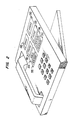
- the main memory in processor l07 contains various feature processing algorithms in addition to routine call processing algorithms. These feature processing algorithms comprise lists of instructions that specify processing operations. Each feature processing algorithm is associated with a specific service request. A feature request is generated at stations l00-0 through l00-n in FIG. l by depressing a feature button appearing on each of the station sets as shown on FIG. 2.
- FIG. 2 illustrates a typical multi-function, multi-appearance, 200 through 203, station set of the digital type.
- the illustrated station set can concurrently serve up to four active calls.
- a subscriber depresses a call appearance button followed by the "dialing" of digits to originate an outgoing call, and depresses a lit call appearance button to answer an incoming call.
- the illustrated station set provides a subscriber with a number of feature buttons 204 through 207 where each button is associated with a specific feature. Such features may include conferencing, transfer, drop and hold.
- a subscriber activates a feature by depressing a feature button, e.g. 205 to generate a service request.
- the routine call processing algorithm contained in the main memory of control processor l07 branches to an associated feature call processing routine to serve the service request.
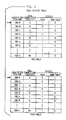
- Control processor l07 maintains in its main memory a number of status tables which are established during call processing. Processor l07 continually updates these tables to reflect the current state, e.g. "on-hook”, “off-hook”, “talk” and “non-talk", associated with each of the station sets of FIG. l.
- FIGS. 3 and 4 illustrate examples of these status tables.
- FIG. 3 illustrates a station status table which indicates the current state of each station l00-0 through l00-n.
- the pre-hold station status table illustrates that station l00-0 is currently "off-hook", i.e. l, and that station l00-3 is currently "on-hook", i.e. l, a "l” is a positive indicator of an associated state.
- This station status table indicates the hook status of each station.
- FIG. 4 illustrates a call status table which indicates the current state of each station l00-0 through l00-n on an identified call connection. For example, as the pre-hold call status table illustrates, station l00-0 is in a "talk" state on call connection A, but in a "non-talk" state, i.e. hold on call connection B. Both the station status table and the call status table are continually updated to reflect the current state of each of the stations l00-0 through l00-n with respect to identified call connections. Further details of these tables are discussed subsequently.
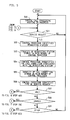
- FIGS. 5, 6, 7 and 8 illustrate in flow chart form the steps required to implement the held party notification feature algorithm.
- the steps required by typical call processing to facilitate the operation of the feature Prior to describing the steps included in the implementation of the subject feature, the following describes the steps required by typical call processing to facilitate the operation of the feature.
- Call processing establishs and disengages connections between stations and services requests generated by station users.
- Processor l07 scans via scanner l06 each station l00-0 through l00-n to detect the generation of a stimulus and/or service request.
- Processor l07 in response to the receipt of a stimulus and/or service request, constantly updates the status tables to indicate the current state of each of the identified stations l00-0 through l00-n during the call processing operations. Call processing performs processing operations based on the information contained in these status tables.
- Step 500 of FIG. 5 indicates that typical call processing operations are in progress and assumes that a number of interconnections between various ones of the station sets of FIG. l have been established. See the pre-hold station status table of FIG. 3 and pre-hold call status table of FIG. 4.
- I step 50l if no service request is generated by any of the stations l00-0 through l00-n, processor l07 returns to typical call processing operations prior to step 50l. However, if a service request is generated from one of the stations l00-0 through l00-n by a user who depresses, for example, a feature button, such as button 204 illustrated on the station set of FIG. 2, conventional call processing branches to step 502 to a service request routine to serve the request.
- a feature button such as button 204 illustrated on the station set of FIG. 2
- station l00-0 is the station generating the request. It is understood that more than one station can generate a request and, that the control processor may service more than one request, concurrently. However, for ease of description assume that only one station, l00-0, is generating a service request at this time.
- Scanner l06 detects the generated service request over path l03-0 from station l00-0 via the associated line port circuit l02-0. Scanner l06 applies an indication of the service request over path l08 to processor l07.
- This indication includes information as to: l) the identity of the station requesting the service; 2) the identity of the active call connection associated with the station requesting the service where, as previously described, each active call connection originating at a single station is assigned a specified identity; and 3) the type of service request generated by the station.
- processor l07 identifies the requesting station, station l00-0 at step 502 and then stores the identity of the requesting station in a location specified in its main memory, step 503. Following the identification of the requesting station, processor l07 identifies the call connection, i.e., connection A or B as shown on the pre-hold call status table of FIG. 4, associated with the requesting station, step 504. Processor l07 stores the identity of the call connection in a specified location of the main memory, step 505. Control processor l07, then, at step 506, identifies the type of service request generated by the identified requesting station.
- step 509 In response to the "other" service request generated by the station set user depressing either button 205, 206 or 207 on the station set of FIG. 2, processor l07 bypasses steps 507 and 508 and goes to step 509, "other". If the generated service request is unavailable to the user, step 509 returns to the typical call processing routine (step 500) to maintain the established call connection and continues scanning the requesting station until another service request is generated. However, if the service is available, step 509 diverts to an associated feature algorithm to process the received "other" service request.
- processor l07 retrieves from its main memory the identity of the requesting station, step 800.
- Processor l07 then scans the previously described status tables of FIGS. 3 and 4 to detect the current state of the requesting station, step 80l.
- the requesting station must be in the appropriate state to satisfy the request. If the station is not in the appropriate state, the service request is abandoned (step not shown). However, if the requesting station is in the appropriate state, processor l07 processes the service request according to the steps of the associated feature processing routine, step 802. No further details are provided since the processing of "other" feature requests comprises no part of the subject invention. The above merely indicates that the control processor responds to a variety of service requests. Following the processing of the "other" service request, processor l07 returns to point A of FIG. 5. Call processing continues until the next service request is generated, step 50l, that requires specialized feature processing.
- station l00-0 is scanning station l00-0 to detect a service request.
- station l00-0 is currently in the states indicated on the pre-hold status tables of FIGS. 3 and 4
- station l00-0 is currently "off-hook”, is included in call connections A and B, and is in a "talk" state on call connection A and a "non-talk" state on call connection B.
- a station user is capable of participating in more than one active call connection at one time, but can only converse on one call connection at a time.
- station l00-0 on call connection A is the requesting station and that a "hold” service request is generated in response to the user of station l00-0 depressing the hold button (204) on the station of FIG. 2.
- control processor l07 has completed steps 50l through 506, as previously described, and identified the service request as a "hold” in step 507 of FIG. 5. If the hold feature is not available, processor l07 does not service the request and returns to step 500. However, assume that "hold" is available to the user and, therefore, processing proceeds on to point B of FIG. 6.
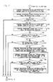
- FIG. 6 illustrates the steps required to remove station set l00-0, hereinafter, the requesting station, from the "talk" state of call connection A while still maintaining an active call connection with station set l00-l, that is, station set l00-0 user puts the station set l00-l user "on-hold”.
- processor l07 retrieves the identity of the requesting station, station set l00-l, at step 600.
- Processor l07 then scans the pre-hold station status table of FIG. 3 to detect of the requesting station, step 60l.
- the pre-hold station status table indicates that the requesting station is currently "off-hook", step 602.
- the routine diverts to point A (FIG. 5) of the call processing routine to await another service request because the station is not in the appropriate state to satisfy the request.
- An "on-hook” further indicates that there is no existing active call connection.
- the hold feature is only operable when the requesting station is "off-hook" and the associated user desires to maintain an active call connection with the user at the associated connected station.
- Processor l07 following validation of the "off-hook" state at step 602, retrieves the identity of the call connection associated with the requesting station, call connection A, from its main memory at step 603.
- Control processor l07 concurrently, scans the pre-hold call status table for the requesting station.
- the pre-hold call status table of FIG. 4 indicates that station set l00-0 is included in connections A and B, step 604.
- Multi-appearance station set users may participate in several active call connections at one time and therefore, the control processor must apply the received service request to the correct call connection otherwise a feature may be inadvertently applied to the wrong call connection of the requesting station.
- the control processor abandons the "hold" routine at step 605 and processing returns to point A of FIG. 5 to await the next service request.
- the requesting station currently, as illustrated in the pre-hold call status table of FIG. 4 has an associated call connection A which matches the retrieved identified call connection A.
- processor l07 scans the pre-hold call status table of FIG. 4 to detect whether the requesting station is currently in the "talk" state, step 606. If the requesting station is not currently in a "talk" state, that is, "non-talk", with respect to the identified connection, the "hold" service request is inapplicable since there is no voice connection to disengage, and therefore, processor l07 abandons the service request and returns to point A of FIG. 5. Assume, however, as the pre-hold call status table of FIG. 4 indicates, that the requesting station l00-0 associated with connection A is in the "talk" state, l.
- Step 607 in response to a validation of the correct state at step 606.
- Processor l07 removes the requesting station l00-0 from the "talk" state of the identified call connection.
- Processor l07 concurrently, updates the call status table to reflect the current state of station l00-0 on connection A. Since an active call connection is still maintained, post-hold station status table of FIG. 3 still indicates that station l00-0 is "off-hook” and post-hold call status table of FIG. 4 indicates that station l00-0 is still on connection A, but is now in the "non-talk" state. Station set l00-l is now on hold, indicating that there is no voice connection between station l00-0 and l00-l. Processor l07 has now served the "hold” service request and returns to typical call processing at point A of FIG. 5. This processing status is maintained until the next service request is generated.
- control processor in response to call processing operations monitors the station sets to detect service requests and, following the identification of the type of service request generated from the stations, call processing implements the appropriate feature processing routine to satisfy the request.
- the feature processing routine processes the service request based on the state of the requesting station as indicated by the status tables contained in the control processor's main memory.
- station set l00-0 is "off-hook” and is maintaining an active "non-talk" connection with station l00-l on identified call connection A.
- Station set l00-0 user has placed station set l00-l user "on-hold”. During this hold interval, the station set l00-l user merely sets down his receiver and waits for a notification indicating the removal of the hold condition by the station set l00-0 user.
- station set l00-0 user has dropped out of the B call connection, which was, as the pre-hold call status table of FIG. 4 indicates, a conference call connection.
- station set l00-0 user completely disengage from the established call connection, call connection B, to re-engage in a voice connection on another call connection, call connection A.
- Station set l00-0 user can place as many parties on hold as there are active call connections, but only one active voice connection can exist at a time. However, for ease of description assume that only one call is "on-hold", and that station set l00-0 user has completely disengaged from the established conference connection B.
- station set l00-0 user wishes to resume a "talk" state connection with station set l00-l user who is currently “on-hold” and awaiting the resumption of the voice connection between the two parties.
- station set l00-l user generates an "un-hold” service request by depressing the call appearance associated with the held call.
- Processor l07 has identified the "un-hold” service request and completed steps 50l through 506 of FIG. 5 to reach step 508. If the service request was inappropriate, as previously described, then, typical call processing is resumed at step 500. However, since the "un-hold" service request is valid, i.e. a hold condition currently exists, processing proceeds to point C of FIG. 7. In response to the "un-hold" service request, control processor l07 begins processing at step 700 of FIG. 7.
- Control processor l07 retrieves the identity of the requesting station, station set l00-0, from its main memory. Processor l07, then, scans the post-hold station status table of FIG. 3, to determine if station set l00-0 is off-hook, steps 70l and 702. As the post-hold station status table of FIG. 3 indicates, station l00-0 is currently "off-hook", l. If station set l00-0 user is "on-hook", processor l07 abandons the service request and returns to point A of FIG. 5 to await another service request since the state of the requesting station is inappropriate for the generated service request. However since the appropriate state exists, processor l07 then proceeds to step 703 and retrieves the identity of the connection, A, from its main memory.
- Processor l07 concurrently scans the post-hold call status table of FIG. 4, step 704, to detect the identified connection of the requesting station. As the post-hold call status table indicates, station set l00-0 is associated with connection A which matches the identified call connection retrieved from the main memory, step 705. Again, this determination is to prevent a mis-service to the requesting station on the wrong connection such as if connection B were still associated with station set l00-0. If no match occurred, then, processing returns to point A of FIG. 5; however, a valid match exists. Processor l07, then, scans at step 706, the post-hold call status table of FIG. 4 to determine if station l00-0 on connection A is in the "non-talk" state, l.
- call processing returns to point A of FIG. 5 to await another service request since the appropriate state associated with the service request is not present.
- the "non-talk" state must exist because the purpose of an "un-hold” request is to re-establish a "talk-state.”
- station l00-0 is in the "non-talk” state on connection A.
- Processor l07 proceeds to step 707 and returns the requesting station to the "talk" state on the identified connection A. At this point, the "hold” condition has been removed from the requesting station.
- Control processor l07 concurrently, updates a call status table (not shown) to reflect that the station set l00-0 user is now in the "talk” state on call connection A.
- Steps 700 through 707 define the states for detecting when the station of an activating party is changed from a "hold” to an "un-hold” state, that is, removal of the hold condition.
- processor l07 immediately reestablishes a voice connection between the activating party and the held party, station l00-0 and station l00-l.
- the parties on the connection may now converse. However, the previously held party must be notified as to the re-establishment of the voice connection between the parties.
- the remaining steps, 708 through 7l0 of FIG. 7, cause the control processor to immediately generate a notification indication to the held party to signal the conclusion of the hold interval such that conversation between the parties may resume.
- Control processor l07 scans the post-hold call status table to identify if any other stations are included in the identified call connection A, step 708. As the post-hold call status table indicates, station set l00-l is included in the identified call connection A, step 709. Processor l07, in response to identifying a station included on the identified call connection, generates a notification indication, e.g. a "ring-ping", to the identified station, step 7l0. This notification indicates that the hold condition has been removed and that the voice connection has been reestablished. The "ring-ping" type of notification alerts the held party of the resumption of the "talk" state. It is well-known that a station of the type described in FIG.
- the held party does not rely on aural monitoring of the station's receiver to hear the voice of the activating party to determine when the talk state is resumed.
- Processor l07 repeats steps 708 through 7l0 to notify each of the stations included on the connection. This process of sequential notification occurs, for example, in a conference call connection where several held parties are involved in the connection. If no further stations require notification, the call processing routine returns to point A of FIG. 5. Processor l07 then resumes typical call processing operations and awaits another service request from any of the station sets l00-0 through l00-n.
- a held party or parties need not aurally monitor the station's receiver for the voice of the activating party to signal the conclusion of the hold interval and the re-establishment of the voice connection.
- the held party merely sets down the station's receiver and continues other activities until a notification is generated at the conclusion of hold interval.
- the above described feature processing arrangement monitors the states of the requesting station to detect when an "un-hold" condition exists and then, provides immediate notification to the held party or parties indicating the removal of the hold condition.
Landscapes
- Engineering & Computer Science (AREA)
- Signal Processing (AREA)
- Multimedia (AREA)
- Physics & Mathematics (AREA)
- Astronomy & Astrophysics (AREA)
- General Physics & Mathematics (AREA)
- Computer Networks & Wireless Communication (AREA)
- Telephonic Communication Services (AREA)
- Sub-Exchange Stations And Push- Button Telephones (AREA)
Applications Claiming Priority (2)
| Application Number | Priority Date | Filing Date | Title |
|---|---|---|---|
| US06/794,536 US4731822A (en) | 1985-11-04 | 1985-11-04 | Held party notification feature |
| US794536 | 1991-11-19 |
Publications (3)
| Publication Number | Publication Date |
|---|---|
| EP0222251A2 true EP0222251A2 (de) | 1987-05-20 |
| EP0222251A3 EP0222251A3 (en) | 1989-03-22 |
| EP0222251B1 EP0222251B1 (de) | 1992-12-30 |
Family
ID=25162924
Family Applications (1)
| Application Number | Title | Priority Date | Filing Date |
|---|---|---|---|
| EP86114935A Expired - Lifetime EP0222251B1 (de) | 1985-11-04 | 1986-10-28 | Verfahren zu Bereitstellung einer Anzeige für einen gehaltenen Teilnehmer. |
Country Status (6)
| Country | Link |
|---|---|
| US (1) | US4731822A (de) |
| EP (1) | EP0222251B1 (de) |
| JP (1) | JPS62112458A (de) |
| KR (1) | KR870005530A (de) |
| CA (1) | CA1253937A (de) |
| DE (1) | DE3687404T2 (de) |
Cited By (2)
| Publication number | Priority date | Publication date | Assignee | Title |
|---|---|---|---|---|
| EP0736994A3 (de) * | 1995-03-08 | 1999-10-27 | Advanced Micro Devices, Inc. | Fernsprechsystem |
| EP1641228A1 (de) * | 2004-09-24 | 2006-03-29 | Siemens Aktiengesellschaft | Signalisieren des Endes eines Wartezustandes einer gehaltenen Telefonieverbindung |
Families Citing this family (24)
| Publication number | Priority date | Publication date | Assignee | Title |
|---|---|---|---|---|
| JPS63158955A (ja) * | 1986-12-23 | 1988-07-01 | Canon Inc | 通信保留制御方式 |
| US4834551A (en) * | 1987-01-14 | 1989-05-30 | Katz James E | Call holding alert system |
| JPH01227562A (ja) * | 1988-03-07 | 1989-09-11 | Nec Corp | 保留解除通知方式 |
| JPH0571056U (ja) * | 1992-03-04 | 1993-09-24 | 極東開発工業株式会社 | 車両のハシゴ積卸装置におけるロック装置 |
| US5436967A (en) * | 1994-02-01 | 1995-07-25 | At&T Corp. | Held party call-back arrangement |
| US6118861A (en) * | 1997-08-14 | 2000-09-12 | Nortel Networks Corporation | Calling party invoked held call monitoring |
| US6031905A (en) * | 1997-09-17 | 2000-02-29 | At&T Corp | Network-based call hold stand by |
| US6141328A (en) * | 1997-09-29 | 2000-10-31 | Qwest Communications International Inc. | Method and system for two-way negotiated call hold |
| US6539088B1 (en) | 2000-03-10 | 2003-03-25 | Giant Communications, Inc. | Electrical connector for connecting an audio source to a caller on hold |
| CN1462539A (zh) * | 2001-05-08 | 2003-12-17 | 皇家菲利浦电子有限公司 | 具有通话保持功能的电话机 |
| US6870919B2 (en) * | 2002-03-29 | 2005-03-22 | Intel Corporation | Mute status reminder for a communication device |
| US20050147227A1 (en) * | 2003-12-31 | 2005-07-07 | France Telecom, S.A. | Method and system for alerting call participant of a change in a call hold status |
| US7684830B2 (en) * | 2005-03-08 | 2010-03-23 | Endtone, Llc | Communication link termination indication signal method and apparatus |
| US20070224984A1 (en) | 2005-03-08 | 2007-09-27 | Muir Brockett Iii | Communication Link Termination Indication Signal and Secondary Signal Method and Apparatus |
| US7881450B1 (en) | 2005-09-15 | 2011-02-01 | Avaya Inc. | Answer on hold notification |
| US9386151B2 (en) | 2007-11-23 | 2016-07-05 | Foncloud, Inc. | System and method for replacing hold-time with a call-back in a contact center environment |
| US8515028B2 (en) | 2007-11-23 | 2013-08-20 | Foncloud, Inc. | System and method for externally mapping an Interactive Voice Response menu |
| US9270817B2 (en) * | 2007-11-23 | 2016-02-23 | Foncloud, Inc. | Method for determining the on-hold status in a call |
| US9288316B2 (en) * | 2007-11-23 | 2016-03-15 | Foncloud, Inc. | System and method for eliminating hold-time in phone calls |
| US8908847B2 (en) * | 2007-11-23 | 2014-12-09 | Foncloud, Inc. | System and method for deep dialing phone systems |
| US8619965B1 (en) | 2010-05-07 | 2013-12-31 | Abraham & Son | On-hold processing for telephonic systems |
| US8891740B2 (en) | 2012-04-11 | 2014-11-18 | International Business Machines Corporation | Voice input state identification |
| US9736317B2 (en) | 2015-02-27 | 2017-08-15 | Cisco Technology, Inc. | Secure mechanism for mute alert |
| US9571651B2 (en) * | 2015-05-27 | 2017-02-14 | Avaya Inc. | Far-end initiated mid-call notification via ring-ping |
Family Cites Families (20)
| Publication number | Priority date | Publication date | Assignee | Title |
|---|---|---|---|---|
| US29078A (en) * | 1860-07-10 | Improvement in seed-planters | ||
| USRE29078E (en) | 1974-03-29 | 1976-12-14 | Bell Telephone Laboratories, Incorporated | Key telephone system |
| US3961142A (en) * | 1974-10-24 | 1976-06-01 | Caffine George S | Method and apparatus for automatically annunciating the completion of a telephone call hold interval |
| US3963873A (en) * | 1975-03-25 | 1976-06-15 | Stromberg-Carlson Corporation | Local transfer arrangement for electronic private automatic branch exchange |
| JPS5294005A (en) * | 1976-02-03 | 1977-08-08 | Nitsuko Ltd | Key telephone system |
| US4028502A (en) * | 1976-02-13 | 1977-06-07 | Inventive Industries, Inc. | Apparatus for adapting multi-line telephone instrument for use by the blind |
| US4169216A (en) * | 1978-05-08 | 1979-09-25 | Northern Telecom Limited | Electronic hold and hold-release circuit for a telephone set in a multiple extension single line telephone system |
| US4258232A (en) * | 1978-11-06 | 1981-03-24 | Tone Commander Systems, Inc. | Line hold circuits |
| US4194093A (en) * | 1978-11-29 | 1980-03-18 | International Telephone And Telegraph Corporation | Key system protective apparatus |
| US4291199A (en) * | 1979-03-28 | 1981-09-22 | Bell Telephone Laboratories, Incorporated | Communication system tracking arrangement |
| US4228324A (en) * | 1979-05-14 | 1980-10-14 | Crest Industries, Inc. | Key telephone system having interstation signalling during hold condition |
| JPS5610766A (en) * | 1979-07-09 | 1981-02-03 | Nec Corp | Talking monitor system |
| JPS5658356A (en) * | 1979-10-18 | 1981-05-21 | Fujitsu Ltd | Call waiting connecting system |
| US4365117A (en) * | 1980-08-07 | 1982-12-21 | Curtis William A | Telephone hold circuit |
| US4424418A (en) * | 1981-05-18 | 1984-01-03 | Bell Telephone Laboratories, Incorporated | Communication system parkhold conferencing |
| US4425479A (en) * | 1982-02-22 | 1984-01-10 | Leon H. Dubner | Apparatus for annunciating the completion of a telephone call hold interval |
| US4506346A (en) * | 1982-12-01 | 1985-03-19 | At&T Bell Laboratories | Programmable cartridge telephone communication system |
| JPS59114954A (ja) * | 1982-12-20 | 1984-07-03 | Nec Corp | 自動キヤンプオン機能を備えた事業所電話交換機 |
| JPS60136498A (ja) * | 1983-12-24 | 1985-07-19 | Matsushita Electric Ind Co Ltd | 電話装置 |
| JPS61167258A (ja) * | 1985-01-18 | 1986-07-28 | Sanyo Electric Co Ltd | 通話保留方式 |
-
1985
- 1985-11-04 US US06/794,536 patent/US4731822A/en not_active Expired - Fee Related
-
1986
- 1986-10-21 CA CA000521056A patent/CA1253937A/en not_active Expired
- 1986-10-28 EP EP86114935A patent/EP0222251B1/de not_active Expired - Lifetime
- 1986-10-28 DE DE8686114935T patent/DE3687404T2/de not_active Expired - Fee Related
- 1986-11-03 KR KR860009240A patent/KR870005530A/ko not_active Ceased
- 1986-11-04 JP JP61260846A patent/JPS62112458A/ja active Pending
Cited By (3)
| Publication number | Priority date | Publication date | Assignee | Title |
|---|---|---|---|---|
| EP0736994A3 (de) * | 1995-03-08 | 1999-10-27 | Advanced Micro Devices, Inc. | Fernsprechsystem |
| EP1641228A1 (de) * | 2004-09-24 | 2006-03-29 | Siemens Aktiengesellschaft | Signalisieren des Endes eines Wartezustandes einer gehaltenen Telefonieverbindung |
| WO2006032690A1 (de) * | 2004-09-24 | 2006-03-30 | Siemens Aktiengesellschaft | Signalisieren des endes eines wartezustandes einer gehaltenen telefonieverbindung |
Also Published As
| Publication number | Publication date |
|---|---|
| EP0222251B1 (de) | 1992-12-30 |
| JPS62112458A (ja) | 1987-05-23 |
| DE3687404T2 (de) | 1993-07-22 |
| EP0222251A3 (en) | 1989-03-22 |
| DE3687404D1 (de) | 1993-02-11 |
| KR870005530A (ko) | 1987-06-09 |
| US4731822A (en) | 1988-03-15 |
| CA1253937A (en) | 1989-05-09 |
Similar Documents
| Publication | Publication Date | Title |
|---|---|---|
| US4731822A (en) | Held party notification feature | |
| US5712902A (en) | Telecommunications answering feature method and apparatus | |
| US5884167A (en) | Method for completing a conference with a personal communications units | |
| KR100528057B1 (ko) | 입중계호에 응답하기 위한 방법 및 가입자 전화 시스템의 기지 장치 | |
| US5479493A (en) | Calling line identification adjunct for use with a communication system | |
| US5937035A (en) | Interswitch telephone status monitoring | |
| US20030053611A1 (en) | Method for providing outgoing call reservation service in exchange system | |
| US5600654A (en) | Multiple call offering method for use with an analog station and an ISDN station that share a directory number | |
| US5317631A (en) | Local switching system | |
| US4446553A (en) | Arrangement for multiple custom calling | |
| JPH01248747A (ja) | Isdn端末のコールウェイティングサービス方式 | |
| US7551733B2 (en) | Methods and devices for establishing an area party line service for telephone calls | |
| KR0138128B1 (ko) | 전화메시지 전달서비스 장치 및 서비스 방법 | |
| KR20010106506A (ko) | 고도 통화 대기 | |
| JP2825122B2 (ja) | 電話交換システム | |
| US6831973B2 (en) | Method and apparatus for executive phone call initiation | |
| KR100454938B1 (ko) | 교환기의다중착신서비스방법 | |
| JPH04252648A (ja) | 交換方式 | |
| JPS63238757A (ja) | 着信サービス制御方式 | |
| JPH0832682A (ja) | 使用者識別電話交換システム及びその通話中着信 制御方法 | |
| KR20010040284A (ko) | 전화 시스템에서의 자동 응답과 메시지 녹음을 위한 방법및 시스템 | |
| JPH05300244A (ja) | 交換機におけるコールウェイティング装置 | |
| JP2002330225A (ja) | 会議通話システム | |
| JPH03201756A (ja) | 応答拒否サービス方式 | |
| JPS63220646A (ja) | 加入者呼出方式 |
Legal Events
| Date | Code | Title | Description |
|---|---|---|---|
| PUAI | Public reference made under article 153(3) epc to a published international application that has entered the european phase |
Free format text: ORIGINAL CODE: 0009012 |
|
| AK | Designated contracting states |
Kind code of ref document: A2 Designated state(s): DE FR GB IT SE |
|
| PUAL | Search report despatched |
Free format text: ORIGINAL CODE: 0009013 |
|
| AK | Designated contracting states |
Kind code of ref document: A3 Designated state(s): DE FR GB IT SE |
|
| 17P | Request for examination filed |
Effective date: 19890904 |
|
| 17Q | First examination report despatched |
Effective date: 19910821 |
|
| GRAA | (expected) grant |
Free format text: ORIGINAL CODE: 0009210 |
|
| AK | Designated contracting states |
Kind code of ref document: B1 Designated state(s): DE FR GB IT SE |
|
| REF | Corresponds to: |
Ref document number: 3687404 Country of ref document: DE Date of ref document: 19930211 |
|
| ET | Fr: translation filed | ||
| ITF | It: translation for a ep patent filed | ||
| PLBE | No opposition filed within time limit |
Free format text: ORIGINAL CODE: 0009261 |
|
| STAA | Information on the status of an ep patent application or granted ep patent |
Free format text: STATUS: NO OPPOSITION FILED WITHIN TIME LIMIT |
|
| 26N | No opposition filed | ||
| PGFP | Annual fee paid to national office [announced via postgrant information from national office to epo] |
Ref country code: DE Payment date: 19940902 Year of fee payment: 9 |
|
| PGFP | Annual fee paid to national office [announced via postgrant information from national office to epo] |
Ref country code: FR Payment date: 19940916 Year of fee payment: 9 |
|
| PGFP | Annual fee paid to national office [announced via postgrant information from national office to epo] |
Ref country code: SE Payment date: 19940920 Year of fee payment: 9 |
|
| PGFP | Annual fee paid to national office [announced via postgrant information from national office to epo] |
Ref country code: GB Payment date: 19940926 Year of fee payment: 9 |
|
| EAL | Se: european patent in force in sweden |
Ref document number: 86114935.9 |
|
| PG25 | Lapsed in a contracting state [announced via postgrant information from national office to epo] |
Ref country code: GB Effective date: 19951028 |
|
| PG25 | Lapsed in a contracting state [announced via postgrant information from national office to epo] |
Ref country code: SE Effective date: 19951029 |
|
| GBPC | Gb: european patent ceased through non-payment of renewal fee |
Effective date: 19951028 |
|
| PG25 | Lapsed in a contracting state [announced via postgrant information from national office to epo] |
Ref country code: FR Effective date: 19960628 |
|
| EUG | Se: european patent has lapsed |
Ref document number: 86114935.9 |
|
| PG25 | Lapsed in a contracting state [announced via postgrant information from national office to epo] |
Ref country code: DE Effective date: 19960702 |
|
| REG | Reference to a national code |
Ref country code: FR Ref legal event code: ST |
|
| PG25 | Lapsed in a contracting state [announced via postgrant information from national office to epo] |
Ref country code: IT Free format text: LAPSE BECAUSE OF NON-PAYMENT OF DUE FEES;WARNING: LAPSES OF ITALIAN PATENTS WITH EFFECTIVE DATE BEFORE 2007 MAY HAVE OCCURRED AT ANY TIME BEFORE 2007. THE CORRECT EFFECTIVE DATE MAY BE DIFFERENT FROM THE ONE RECORDED. Effective date: 20051028 |