EP0222344A2 - Dispositif à tester et à trier des composants électroniques - Google Patents
Dispositif à tester et à trier des composants électroniques Download PDFInfo
- Publication number
- EP0222344A2 EP0222344A2 EP86115464A EP86115464A EP0222344A2 EP 0222344 A2 EP0222344 A2 EP 0222344A2 EP 86115464 A EP86115464 A EP 86115464A EP 86115464 A EP86115464 A EP 86115464A EP 0222344 A2 EP0222344 A2 EP 0222344A2
- Authority
- EP
- European Patent Office
- Prior art keywords
- magazine
- cassette
- input
- cassette carriage
- carriage
- Prior art date
- Legal status (The legal status is an assumption and is not a legal conclusion. Google has not performed a legal analysis and makes no representation as to the accuracy of the status listed.)
- Granted
Links
Images

Classifications
-
- B—PERFORMING OPERATIONS; TRANSPORTING
- B07—SEPARATING SOLIDS FROM SOLIDS; SORTING
- B07C—POSTAL SORTING; SORTING INDIVIDUAL ARTICLES, OR BULK MATERIAL FIT TO BE SORTED PIECE-MEAL, e.g. BY PICKING
- B07C5/00—Sorting according to a characteristic or feature of the articles or material being sorted, e.g. by control effected by devices which detect or measure such characteristic or feature; Sorting by manually actuated devices, e.g. switches
- B07C5/34—Sorting according to other particular properties
- B07C5/344—Sorting according to other particular properties according to electric or electromagnetic properties
-
- B—PERFORMING OPERATIONS; TRANSPORTING
- B07—SEPARATING SOLIDS FROM SOLIDS; SORTING
- B07C—POSTAL SORTING; SORTING INDIVIDUAL ARTICLES, OR BULK MATERIAL FIT TO BE SORTED PIECE-MEAL, e.g. BY PICKING
- B07C5/00—Sorting according to a characteristic or feature of the articles or material being sorted, e.g. by control effected by devices which detect or measure such characteristic or feature; Sorting by manually actuated devices, e.g. switches
- B07C5/36—Sorting apparatus characterised by the means used for distribution
Definitions
- the invention relates to a device according to the preamble of claim 1.
- Such a device is known.
- the input magazine is displaceable perpendicular to the plane formed in the magazine channels.
- the magazine channels are processed one after the other, i.e. the input magazine is moved one magazine channel width at a time when the components of a magazine channel have been separated and fed to the test unit.
- the output magazine of the known device is stationary.
- the components tested by the test unit are transferred to the selected magazine channel of the output magazine and assigned to a sort class by means of a shuttle which can be moved across the magazine channels of the output magazine and which takes a tested component from the test unit and feeds it to the magazine channel mentioned. Then the shuttle drives back to the delivery opening of the test unit.
- the magazine channels of the input magazine have been filled with unchecked components and the tested components have been removed from the magazine channels of the output magazine by hand.
- a magazine bar filled with components is attached to the respective input of a magazine channel of the input magazine, so that the components can slide out of the magazine bar into the magazine channel mentioned due to the inclination.
- the tested components are removed from the magazine channels of the output magazine in an analogous manner.
- an empty magazine rod is attached to the outlet of the magazine channel, so that the components can slide out of the magazine channel due to the inclination into the empty magazine rod.
- the invention has for its object to improve a device of the type described above in such a way that the manual work to be performed by an operator of filling and removing the device is reduced.
- the cassette slide on the cassette slide carrier can be moved into a position in which a magazine bar that is still filled corresponds to the magazine channel of the input magazine that has just been emptied.
- the transfer can .angsmagazin in sliding Ei.n 9 in this way of building components of magazine rods of the cassette to the magazine channels of the input magazine at a fixed location be made.
- This proves to be particularly advantageous if the input magazine and the test unit are arranged in a gas-filled climatic chamber.
- the climatic chamber is supplied with either heated or cooled gas.
- the cooled gas Especially because of the cooled gas, it must be under pressure in the climatic chamber. This is because otherwise icing would occur in the climate chamber.
- the gas under pressure should as far as possible not escape or, with in other words, those unavoidable openings in the climate chamber through which gas can escape should be kept as small as possible.
- Such an unavoidable opening is the place where components are fed to the input magazine. Since, as mentioned, this location remains unchanged, that is to say it is at a fixed point, the passage opening at most needs to be the size of a component.
- a plurality of cassettes can be arranged next to one another on a cassette carriage, an additional possibility of moving the cassettes on the cassette carriage having to be provided.
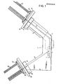
- 1 denotes a device for checking and sorting ICs.
- This has an input magazine 2, which is provided with a multiplicity of parallel and inclined magazine channels.
- the magazine channels are arranged one behind the other perpendicular to the plane of the drawing.
- the input magazine 2 can be moved perpendicular to the plane of the drawing in the plane defined by the magazine channels.
- the input magazine 2 is arranged in a climate chamber 3, which is filled with pressurized air-conditioned gas.
- a test unit 4 is connected to the input magazine.
- the test unit 4 is supplied with consecutively unchecked components from a magazine channel of the input magazine 2 brought into alignment with the input of the test unit, after they have been separated beforehand.
- the components are then checked in the test unit 4 and assigned to a sorting class.
- the corresponding sorting signal controls the drive of a movable shuttle 5, which takes a tested component from the test unit 4 and feeds it to a magazine channel of a fixed output magazine 6.
- the output magazine 6 has a multiplicity of magazines running in parallel channels that lie in a plane perpendicular to the drawing plane.
- the channels of the output magazine 6 are also inclined, so that the components slide downward due to gravity. The same applies to the magazine channels of the input magazine 2.
- Carrier jaws 7 are attached to the side walls of the device 1 in the area of the input magazine 2, between which a pivot shaft 9 extends.
- a cassette carriage carrier 8 On this pivot shaft 9 there is a cassette carriage carrier 8 which in turn carries a cassette carriage 10 which can be displaced in the direction of the double arrow on the cassette carriage carrier.
- the cassette carriage 10 carries an exchangeable cassette 11, in which in turn a multiplicity of magazine bars 12 are interchangeably arranged.
- Lateral support jaws 7a are also fastened at the outlet of the device 1 in the region of the outlet magazine 6, between which a pivot shaft 9a extends.
- a cassette carriage carrier 8a which has a cassette carriage 10a, which can likewise be displaced in the direction of the double arrow, is pivotably attached to this.
- the cassette carriage 10a carries a cassette 11a with magazine bars 12a. The situation here is completely analogous to that of the cassette carriage carrier with cassette carriage at the entrance to the device. Therefore, only one of these two additional devices will be described below.
- Figure 2 show. the carrier cheek 7, the cassette carriage carrier 8, the cassette carriage 10 and the cassette 11 in an enlarged view.
- the cassette carriage carrier 8 is pivotally attached to the pivot shaft 9 by means of link plates 13.
- the link plates 13 (only one of which is visible in FIG. 2) sit on a base plate 14.
- Two side walls 15 are fastened to the base plate 14 (only one of which is visible in FIG. 2).
- Guide rails 16 extend inwards from the side walls 15.
- the cassette carriage 10 runs on these guide rails 16 with guide rollers 35, 36 attached to it.
- the base plate 14 of the cassette carriage carrier 8 On the base plate 14 of the cassette carriage carrier 8, holders 16, 17 are also provided for a locking rail 17, the meaning of which will be explained below. Furthermore, the base plate 14 of the cassette carriage carrier 8 has an opening 18 through which a clamping device 19 which can be actuated by a hand lever 20 extends. By actuating the hand lever 20, the cassette carrier slide 8 can be clamped or released on the carrier cheeks 7 such that the cassette carrier carrier 8 can be pivoted away from the device 1 about the pivot shaft 9.
- the base plate 14 is provided with a further opening 21 through which a mouthpiece 23 extends, which is connected to the base plate 14 by a mounting bracket 22 and a bearing pin 24.
- the mouthpiece 23 has a transfer channel 28, which in each case connects the outlet of a magazine rod 12 located in a cassette 11 to a magazine channel of the input magazine.
- a conveyor wheel 25 projects into the transfer channel 28 and, in conjunction with a light barrier consisting of light transmitter 26 and light receiver 27, forms a separating device known per se.
- the components 51 emerging from a magazine rod are separated with the feed wheel 25 and then fed to a magazine channel of the input magazine 2.
- a tongue 29 is located on the end of the mouthpiece 23 facing the input magazine 2, which tongue engages in a groove 52 on the displaceable input magazine and ensures that the transfer channel 28 in any case with a magazine channel of the input magazine 2 in the height corresponds.
- the cassette carriage 10 is provided on its underside with a toothed rack 33 which has a plurality of toothed slots 34.
- An eccentric drive for the cassette carriage 10 is located on the base plate 14 of the cassette slide carrier 8.
- a carrier disk with two eccentric pins 31, 32 is visible from this, each of which engages in a toothed slot 34.
- This known transport mechanism ensures a precisely defined advancement of the cassette carriage 10 and, in the position shown, the eccentric pins 31, 32, a self-locking mechanism against displacement.
- the holder 38 is provided with a cylindrical locking element 40 which can engage in a wedge-shaped recess 39 on the cassette 11.
- the holder 38a carries a two-armed lever 43, one arm of which can be actuated as a hand lever and the other arm also has a cylindrical latching element 42 which engages in a corresponding wedge-shaped latching recess 41 in the cassette 11. The cassette can be released or locked by pivoting the lever 43.
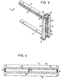
- a cassette is shown in more detail in FIGS. 3 and 4.
- This consists of two side parts 44, 45, which are connected by interchangeable spacers 46, 47.
- the cassette can be used for different bar magazines 12.
- the side parts 44, 45 On the inside, the side parts 44, 45 have closure strips 48, 49 which are pressed inwards by means of springs (not shown) into the closed position and thereby partially close the outputs of the magazine rods 12, so that no components can emerge from the magazine rods 12.
- the side parts 44, 45 have receiving slots 50 for the magazine rods 12 on their inside. In this way, a plurality of magazine bars 12 can be inserted into the cassette 11 in parallel.
- the cassette carriage 10 is shown in a position in which components from magazine bars 12 to the input magazine 2 cannot yet be transferred via the mouthpiece 23.
- only components 51 can emerge from the magazine rod 12 which is aligned with the transfer channel 28 of the mouthpiece 23.
- the remaining magazine bars 12, which are still filled, are closed by the closure rail 17 described above, which lies in the gap between the two closure strips 48, 49 and is firmly connected to the cassette slide carrier 8.
- FIGS. 2 to 4 describe the additional device in connection with the input magazine.
- the function of the additional device with the output magazine is analog.
- the feed wheel 25 of the separating device only has to convey in the opposite direction.
Landscapes
- Testing Of Individual Semiconductor Devices (AREA)
- Warehouses Or Storage Devices (AREA)
- Testing Electric Properties And Detecting Electric Faults (AREA)
- Testing Or Measuring Of Semiconductors Or The Like (AREA)
Priority Applications (1)
| Application Number | Priority Date | Filing Date | Title |
|---|---|---|---|
| AT86115464T ATE68115T1 (de) | 1985-11-11 | 1986-11-07 | Vorrichtung zum pruefen und sortieren von elektronischen bauelementen. |
Applications Claiming Priority (2)
| Application Number | Priority Date | Filing Date | Title |
|---|---|---|---|
| DE3539965 | 1985-11-11 | ||
| DE19853539965 DE3539965A1 (de) | 1985-11-11 | 1985-11-11 | Vorrichtung zum pruefen und sortieren von elektronischen bauelementen |
Publications (3)
| Publication Number | Publication Date |
|---|---|
| EP0222344A2 true EP0222344A2 (fr) | 1987-05-20 |
| EP0222344A3 EP0222344A3 (en) | 1988-02-03 |
| EP0222344B1 EP0222344B1 (fr) | 1991-10-09 |
Family
ID=6285687
Family Applications (1)
| Application Number | Title | Priority Date | Filing Date |
|---|---|---|---|
| EP86115464A Expired - Lifetime EP0222344B1 (fr) | 1985-11-11 | 1986-11-07 | Dispositif à tester et à trier des composants électroniques |
Country Status (4)
| Country | Link |
|---|---|
| US (1) | US4778063A (fr) |
| EP (1) | EP0222344B1 (fr) |
| AT (1) | ATE68115T1 (fr) |
| DE (2) | DE3539965A1 (fr) |
Families Citing this family (44)
| Publication number | Priority date | Publication date | Assignee | Title |
|---|---|---|---|---|
| US4941795A (en) * | 1988-11-21 | 1990-07-17 | At&T Bell Laboratories | Component insertion machine apparatus |
| JPH0643204B2 (ja) * | 1989-08-26 | 1994-06-08 | 吉田工業株式会社 | スライダー補給装置 |
| US5116185A (en) * | 1990-05-01 | 1992-05-26 | Lsi Logic Corp. | Vibratory tube-to-tube transfer system |
| US5117963A (en) * | 1990-12-12 | 1992-06-02 | Micron Technology, Inc. | System for automated handling of symmetrical supply tubes |
| US5316649A (en) * | 1991-03-05 | 1994-05-31 | The United States Of America As Represented By The United States Department Of Energy | High frequency reference electrode |
| TW287235B (fr) * | 1994-06-30 | 1996-10-01 | Zenshin Test Co | |
| DE19827458C2 (de) * | 1998-06-19 | 2001-10-11 | Helmuth Heigl | Vereinzelungsvorrichtung für Bauelemente |
| US8549912B2 (en) | 2007-12-18 | 2013-10-08 | Teradyne, Inc. | Disk drive transport, clamping and testing |
| US7996174B2 (en) | 2007-12-18 | 2011-08-09 | Teradyne, Inc. | Disk drive testing |
| US20090262455A1 (en) | 2008-04-17 | 2009-10-22 | Teradyne, Inc. | Temperature Control Within Disk Drive Testing Systems |
| US8102173B2 (en) | 2008-04-17 | 2012-01-24 | Teradyne, Inc. | Thermal control system for test slot of test rack for disk drive testing system with thermoelectric device and a cooling conduit |
| US8305751B2 (en) | 2008-04-17 | 2012-11-06 | Teradyne, Inc. | Vibration isolation within disk drive testing systems |
| US8041449B2 (en) | 2008-04-17 | 2011-10-18 | Teradyne, Inc. | Bulk feeding disk drives to disk drive testing systems |
| US8238099B2 (en) | 2008-04-17 | 2012-08-07 | Teradyne, Inc. | Enclosed operating area for disk drive testing systems |
| US8095234B2 (en) | 2008-04-17 | 2012-01-10 | Teradyne, Inc. | Transferring disk drives within disk drive testing systems |
| US8160739B2 (en) | 2008-04-17 | 2012-04-17 | Teradyne, Inc. | Transferring storage devices within storage device testing systems |
| US7848106B2 (en) | 2008-04-17 | 2010-12-07 | Teradyne, Inc. | Temperature control within disk drive testing systems |
| US7945424B2 (en) | 2008-04-17 | 2011-05-17 | Teradyne, Inc. | Disk drive emulator and method of use thereof |
| US8117480B2 (en) | 2008-04-17 | 2012-02-14 | Teradyne, Inc. | Dependent temperature control within disk drive testing systems |
| CN102112887B (zh) | 2008-06-03 | 2015-06-10 | 泰拉丁公司 | 处理存储设备 |
| US8687356B2 (en) | 2010-02-02 | 2014-04-01 | Teradyne, Inc. | Storage device testing system cooling |
| US8116079B2 (en) | 2009-07-15 | 2012-02-14 | Teradyne, Inc. | Storage device testing system cooling |
| US8628239B2 (en) | 2009-07-15 | 2014-01-14 | Teradyne, Inc. | Storage device temperature sensing |
| US8547123B2 (en) | 2009-07-15 | 2013-10-01 | Teradyne, Inc. | Storage device testing system with a conductive heating assembly |
| US7995349B2 (en) | 2009-07-15 | 2011-08-09 | Teradyne, Inc. | Storage device temperature sensing |
| US8466699B2 (en) | 2009-07-15 | 2013-06-18 | Teradyne, Inc. | Heating storage devices in a testing system |
| US7920380B2 (en) | 2009-07-15 | 2011-04-05 | Teradyne, Inc. | Test slot cooling system for a storage device testing system |
| US9779780B2 (en) | 2010-06-17 | 2017-10-03 | Teradyne, Inc. | Damping vibrations within storage device testing systems |
| US8687349B2 (en) | 2010-07-21 | 2014-04-01 | Teradyne, Inc. | Bulk transfer of storage devices using manual loading |
| US9001456B2 (en) | 2010-08-31 | 2015-04-07 | Teradyne, Inc. | Engaging test slots |
| US9459312B2 (en) | 2013-04-10 | 2016-10-04 | Teradyne, Inc. | Electronic assembly test system |
| US10845410B2 (en) | 2017-08-28 | 2020-11-24 | Teradyne, Inc. | Automated test system having orthogonal robots |
| US10725091B2 (en) | 2017-08-28 | 2020-07-28 | Teradyne, Inc. | Automated test system having multiple stages |
| US11226390B2 (en) | 2017-08-28 | 2022-01-18 | Teradyne, Inc. | Calibration process for an automated test system |
| US10948534B2 (en) | 2017-08-28 | 2021-03-16 | Teradyne, Inc. | Automated test system employing robotics |
| US10983145B2 (en) | 2018-04-24 | 2021-04-20 | Teradyne, Inc. | System for testing devices inside of carriers |
| US10775408B2 (en) | 2018-08-20 | 2020-09-15 | Teradyne, Inc. | System for testing devices inside of carriers |
| US11754596B2 (en) | 2020-10-22 | 2023-09-12 | Teradyne, Inc. | Test site configuration in an automated test system |
| US11899042B2 (en) | 2020-10-22 | 2024-02-13 | Teradyne, Inc. | Automated test system |
| US11867749B2 (en) | 2020-10-22 | 2024-01-09 | Teradyne, Inc. | Vision system for an automated test system |
| US11953519B2 (en) | 2020-10-22 | 2024-04-09 | Teradyne, Inc. | Modular automated test system |
| US11754622B2 (en) | 2020-10-22 | 2023-09-12 | Teradyne, Inc. | Thermal control system for an automated test system |
| US12007411B2 (en) | 2021-06-22 | 2024-06-11 | Teradyne, Inc. | Test socket having an automated lid |
| US12699008B2 (en) | 2023-05-15 | 2026-08-04 | Teradyne, Inc. | Test systems configured to test devices at different temperatures |
Family Cites Families (19)
| Publication number | Priority date | Publication date | Assignee | Title |
|---|---|---|---|---|
| DE225882C (fr) * | ||||
| US3308977A (en) * | 1965-10-04 | 1967-03-14 | Ibm | Automatic tray handler |
| US3716786A (en) * | 1970-10-02 | 1973-02-13 | Cogar Corp | Module tester and sorter for use in a module test system |
| US3727757A (en) * | 1972-06-12 | 1973-04-17 | C Boissicat | Dip handling apparatus |
| US3896935A (en) * | 1973-11-26 | 1975-07-29 | Ramsey Eng Co | Integrated circuit handler |
| US4049123A (en) * | 1976-06-01 | 1977-09-20 | Western Electric Company, Inc. | Methods of and apparatus for sorting articles in accordance with their resistivity and thickness |
| US4124132A (en) * | 1977-05-18 | 1978-11-07 | Sola Basic Industries, Inc. | Magazine apparatus for semiconductor processing device |
| US4234418A (en) * | 1978-06-23 | 1980-11-18 | Contrel Corporation | Dip-handling apparatus |
| DE2855913C2 (de) * | 1978-12-23 | 1983-05-19 | Licentia Patent-Verwaltungs-Gmbh, 6000 Frankfurt | Vorrichtung zum Sortieren von Bauelementen |
| JPS56168566A (en) * | 1980-05-30 | 1981-12-24 | Toshiba Corp | Ic autohandler |
| JPS5896258A (ja) * | 1981-12-03 | 1983-06-08 | Fujitsu Ltd | 電子部品テスタ用オ−トハンドラにおける部品ケ−スドツキング機構 |
| US4500246A (en) * | 1983-03-01 | 1985-02-19 | Universal Instruments Corporation | Indexed feed of electronic component supply tubes |
| US4506213A (en) * | 1983-07-18 | 1985-03-19 | Sym-Tek Systems, Inc. | Electronic device handler |
| DE3340185A1 (de) * | 1983-11-07 | 1985-05-15 | Multitest Elektronische Systeme GmbH, 8200 Rosenheim | Vorrichtung zum aufnehmen von bauteilen, insbesondere von integrierten chips, in einem eingangs- und/oder ausgangsmagazin einer bauteile-pruefmaschine |
| DE3340182A1 (de) * | 1983-11-07 | 1985-05-15 | Hans Heinrich 8000 München Willberg | Vorrichtung zum weiterleiten von bauteilen, insbesondere von integrierten chips, von einem eingangsmagazin zu einem ausgangsmagazin |
| US4588092A (en) * | 1983-11-15 | 1986-05-13 | Automated Electronic Technology, Inc. | Integrated circuit handling and contact system |
| US4618305A (en) * | 1983-11-23 | 1986-10-21 | Daymarc Corporation | Automatic feed apparatus and process for integrated circuits stored in tubes |
| EP0382264B1 (fr) * | 1984-06-29 | 1994-06-15 | Advantest Corporation | Equipement d'essai pour IC (circuit intégré) |
| DE3505700A1 (de) * | 1985-02-19 | 1986-08-21 | Microhandling Handhabungsgeräte GmbH, 8000 München | Vorrichtung zum magazinieren von laenglichen verpackungseinheiten fuer bauteile, insbesondere fuer integrierte, elektronische schaltkreise (ics) |
-
1985
- 1985-11-11 DE DE19853539965 patent/DE3539965A1/de not_active Withdrawn
-
1986
- 1986-10-22 US US06/921,434 patent/US4778063A/en not_active Expired - Fee Related
- 1986-11-07 DE DE8686115464T patent/DE3681877D1/de not_active Expired - Lifetime
- 1986-11-07 EP EP86115464A patent/EP0222344B1/fr not_active Expired - Lifetime
- 1986-11-07 AT AT86115464T patent/ATE68115T1/de not_active IP Right Cessation
Also Published As
| Publication number | Publication date |
|---|---|
| DE3681877D1 (de) | 1991-11-14 |
| US4778063A (en) | 1988-10-18 |
| EP0222344B1 (fr) | 1991-10-09 |
| DE3539965A1 (de) | 1987-05-14 |
| ATE68115T1 (de) | 1991-10-15 |
| EP0222344A3 (en) | 1988-02-03 |
Similar Documents
| Publication | Publication Date | Title |
|---|---|---|
| EP0222344B1 (fr) | Dispositif à tester et à trier des composants électroniques | |
| EP0204291B1 (fr) | Dispositif à tester et trier des composants électroniques, en particulier des puces intégrées | |
| DE4314613A1 (de) | Verpackungsmaschine | |
| DE69700291T2 (de) | Vorrichtung zum Ablängen und Formen von Stahlstäben, insbesondere von Betonbewehrungsstäben | |
| EP0253015A1 (fr) | Système de transport pour dispositif de test de composants électroniques | |
| DE3644423C2 (fr) | ||
| EP2939767A2 (fr) | Magasin de chargement de barres de matériau | |
| DE2849751C2 (de) | Vorrichtung zum Vereinzeln von ein loses Bündel bildenden abgelängten Drähten, insbesondere zwechs Drahtzufuhr zu einer Verarbeitungsmaschine | |
| DE3221620A1 (de) | Vorrichtung zum anbringen von komponenten | |
| DE4435981C2 (de) | Einrichtung zum Zuführen von zu verpackenden Produkten zu einer Verpackungsmaschine | |
| DE3539957A1 (de) | Magazinbe- und entladevorrichtung fuer unbestueckte und bestueckte platinen zur versorgung eines bestueckungsautomaten | |
| DE3531120C2 (de) | Einrichtung zum Prüfen und Sortieren von elektronischen Bauelementen, insbesondere integrierten Chips | |
| DE2807573C2 (de) | Vorrichtung zum Einbringen von stiftförmigen Einzelteilen in Haltekörper | |
| EP0143990B1 (fr) | Dispositif pour tester et trier des composants electroniques, en particulier des chips intégrés | |
| EP0223189A1 (fr) | Dispositif pour tester et trier des composants électroniques | |
| DE19822998A1 (de) | Vorrichtung zum Einbringen von gestapelten Kuverts in einen Transportkasten | |
| EP0807480A1 (fr) | Dispositif pour transporter des barres individuelles entre machines utils | |
| DE8613183U1 (de) | Auswechselbare Farbbandkassette für Drucker | |
| AT404439B (de) | Vorrichtung zum verteilen von stabförmigen elementen | |
| DE102007022845A1 (de) | Befüllmagazin zum Befüllen von Schachtschragen sowie Befüllstation mit einem solchen Befüllmagazin | |
| DE1703224C3 (de) | Taktweise arbeitende Mehretagenpresse zur Herstellung von Spanplatten o.dgl | |
| WO2025240990A1 (fr) | Dispositif de retenue | |
| DD214309A1 (de) | Vorrichtung zum distanzieren und sortieren von walzstaeben | |
| DE19531023A1 (de) | Vorrichtung zur Anordnung von Behältern für deren Lagerung | |
| DD145450A3 (de) | Einrichtung zum sortieren und stapeln von leitungsverbindungen |
Legal Events
| Date | Code | Title | Description |
|---|---|---|---|
| PUAI | Public reference made under article 153(3) epc to a published international application that has entered the european phase |
Free format text: ORIGINAL CODE: 0009012 |
|
| AK | Designated contracting states |
Kind code of ref document: A2 Designated state(s): AT BE CH DE FR GB IT LI LU NL SE |
|
| PUAL | Search report despatched |
Free format text: ORIGINAL CODE: 0009013 |
|
| AK | Designated contracting states |
Kind code of ref document: A3 Designated state(s): AT BE CH DE FR GB IT LI LU NL SE |
|
| 17P | Request for examination filed |
Effective date: 19880720 |
|
| 17Q | First examination report despatched |
Effective date: 19880927 |
|
| GRAA | (expected) grant |
Free format text: ORIGINAL CODE: 0009210 |
|
| AK | Designated contracting states |
Kind code of ref document: B1 Designated state(s): AT BE CH DE FR GB IT LI LU NL SE |
|
| PG25 | Lapsed in a contracting state [announced via postgrant information from national office to epo] |
Ref country code: IT Free format text: LAPSE BECAUSE OF FAILURE TO SUBMIT A TRANSLATION OF THE DESCRIPTION OR TO PAY THE FEE WITHIN THE PRESCRIBED TIME-LIMIT;WARNING: LAPSES OF ITALIAN PATENTS WITH EFFECTIVE DATE BEFORE 2007 MAY HAVE OCCURRED AT ANY TIME BEFORE 2007. THE CORRECT EFFECTIVE DATE MAY BE DIFFERENT FROM THE ONE RECORDED. Effective date: 19911009 Ref country code: NL Effective date: 19911009 Ref country code: GB Effective date: 19911009 Ref country code: BE Effective date: 19911009 Ref country code: SE Effective date: 19911009 |
|
| REF | Corresponds to: |
Ref document number: 68115 Country of ref document: AT Date of ref document: 19911015 Kind code of ref document: T |
|
| PG25 | Lapsed in a contracting state [announced via postgrant information from national office to epo] |
Ref country code: AT Effective date: 19911107 |
|
| REF | Corresponds to: |
Ref document number: 3681877 Country of ref document: DE Date of ref document: 19911114 |
|
| PG25 | Lapsed in a contracting state [announced via postgrant information from national office to epo] |
Ref country code: CH Effective date: 19911130 Ref country code: LU Free format text: LAPSE BECAUSE OF NON-PAYMENT OF DUE FEES Effective date: 19911130 Ref country code: LI Effective date: 19911130 |
|
| EN | Fr: translation not filed | ||
| PG25 | Lapsed in a contracting state [announced via postgrant information from national office to epo] |
Ref country code: FR Effective date: 19920228 |
|
| NLV1 | Nl: lapsed or annulled due to failure to fulfill the requirements of art. 29p and 29m of the patents act | ||
| GBV | Gb: ep patent (uk) treated as always having been void in accordance with gb section 77(7)/1977 [no translation filed] | ||
| REG | Reference to a national code |
Ref country code: CH Ref legal event code: PL |
|
| PLBE | No opposition filed within time limit |
Free format text: ORIGINAL CODE: 0009261 |
|
| STAA | Information on the status of an ep patent application or granted ep patent |
Free format text: STATUS: NO OPPOSITION FILED WITHIN TIME LIMIT |
|
| 26N | No opposition filed | ||
| REG | Reference to a national code |
Ref country code: FR Ref legal event code: ST |
|
| PGFP | Annual fee paid to national office [announced via postgrant information from national office to epo] |
Ref country code: DE Payment date: 19930129 Year of fee payment: 7 |
|
| PG25 | Lapsed in a contracting state [announced via postgrant information from national office to epo] |
Ref country code: DE Effective date: 19940802 |