EP0222375A2 - Aufrichtevorrichtung für die Anbringung an Krankenhausbetten - Google Patents
Aufrichtevorrichtung für die Anbringung an Krankenhausbetten Download PDFInfo
- Publication number
- EP0222375A2 EP0222375A2 EP86115666A EP86115666A EP0222375A2 EP 0222375 A2 EP0222375 A2 EP 0222375A2 EP 86115666 A EP86115666 A EP 86115666A EP 86115666 A EP86115666 A EP 86115666A EP 0222375 A2 EP0222375 A2 EP 0222375A2
- Authority
- EP
- European Patent Office
- Prior art keywords
- bearing
- holder
- oval
- coupling
- oval tube
- Prior art date
- Legal status (The legal status is an assumption and is not a legal conclusion. Google has not performed a legal analysis and makes no representation as to the accuracy of the status listed.)
- Granted
Links
- 230000008878 coupling Effects 0.000 claims abstract description 34
- 238000010168 coupling process Methods 0.000 claims abstract description 34
- 238000005859 coupling reaction Methods 0.000 claims abstract description 34
- 230000006835 compression Effects 0.000 claims description 8
- 238000007906 compression Methods 0.000 claims description 8
- 239000004033 plastic Substances 0.000 claims description 4
- 239000004952 Polyamide Substances 0.000 claims description 2
- 229920002647 polyamide Polymers 0.000 claims description 2
- HEMHJVSKTPXQMS-UHFFFAOYSA-M Sodium hydroxide Chemical compound [OH-].[Na+] HEMHJVSKTPXQMS-UHFFFAOYSA-M 0.000 claims 1
- 101100298222 Caenorhabditis elegans pot-1 gene Proteins 0.000 description 7
- 125000006850 spacer group Chemical group 0.000 description 4
- 230000001681 protective effect Effects 0.000 description 3
- 239000000725 suspension Substances 0.000 description 3
- 210000000078 claw Anatomy 0.000 description 2
- 101150038956 cup-4 gene Proteins 0.000 description 2
- 229910001018 Cast iron Inorganic materials 0.000 description 1
- 229910001208 Crucible steel Inorganic materials 0.000 description 1
- 230000006978 adaptation Effects 0.000 description 1
- 239000000853 adhesive Substances 0.000 description 1
- 230000001070 adhesive effect Effects 0.000 description 1
- 238000006073 displacement reaction Methods 0.000 description 1
- 239000000463 material Substances 0.000 description 1
- 239000002184 metal Substances 0.000 description 1
- 229910052751 metal Inorganic materials 0.000 description 1
- 239000007769 metal material Substances 0.000 description 1
Images


Classifications
-
- A—HUMAN NECESSITIES
- A61—MEDICAL OR VETERINARY SCIENCE; HYGIENE
- A61G—TRANSPORT, PERSONAL CONVEYANCES, OR ACCOMMODATION SPECIALLY ADAPTED FOR PATIENTS OR DISABLED PERSONS; OPERATING TABLES OR CHAIRS; CHAIRS FOR DENTISTRY; FUNERAL DEVICES
- A61G7/00—Beds specially adapted for nursing; Devices for lifting patients or disabled persons
- A61G7/05—Parts, details or accessories of beds
- A61G7/053—Aids for getting into, or out of, bed, e.g. steps, chairs, cane-like supports
- A61G7/0533—Lifting poles
Definitions
- the invention relates to an erection device for attachment to hospital beds according to the preamble of claim 1.
- Such an erecting device has become known, for example, with the subject of DE-OS 33 27 32O.
- Raising devices of this type are used in particular for freshly operated or handicapped patients, the patient lying in bed gripping the triangular-shaped handle with his hands and pulling up on it.
- the oval tube is pivotally mounted in the holder so that the patient can swing over the rotation of the oval tube in the holder to the edge of the bed by stopping at the handle.
- the coupling which prevents rotation, is intended to ensure that the pivotable oval tube is fixed in the holder in any pivot position. This prevents the oval tube from swinging out too far and, for example, from damaging objects standing next to the bed.
- the clutch consists of a dog clutch, which can be engaged against the spring force of a compression spring.
- a disadvantage of this arrangement is that it is not possible to lock this coupling in any intermediate positions, because only a certain angle of rotation can be locked by the tooth division of the intermeshing claw coupling.
- the invention has for its object to develop an erecting device of the type mentioned in such a way that it can be locked in any rotational position while avoiding early wear of the coupling.
- the invention is characterized in that the coupling consists of a coupling part which is connected in a rotationally fixed manner to the oval tube in the axial extension of the oval tube and which has a conical axial extension which is in an associated conical recess of a radially expandable brake shoe attacks, which can be pressed with its outer circumference non-positively to bear against the inside of a coupling pot receiving the coupling.
- a feature of the invention is therefore that the oval tube is connected in a rotationally fixed manner to an axial extension designed as a cone and can be axially engaged with this cone in an associated conical recess of a radially expandable brake shoe.
- the brake shoe consists of a plurality of segment-shaped parts which are separated from one another by radial slots, with an all-embracing tension spring being arranged in an annular groove on the outer circumference of the brake shoe.
- segment-shaped parts then come to rest with their outer circumference on the inside of a lower bearing pot, which is provided on the inside with a corrugation running in the axial direction, which acts as a friction-increasing surface for the outer surfaces of the brake shoe pressed against it.
- the coupling part which is connected to the oval tube in a rotationally fixed manner, consists of a metal part and the associated brake shoes consist of a polyamide plastic.
- the coupling part which is connected to the oval tube in a rotationally fixed manner, consists of a metal part and the associated brake shoes consist of a polyamide plastic.
- the hospital bed 25 shown in FIG. 1 consists in a known manner of a bed frame 28, at the front and rear end of which a foot frame 26 and a head frame 27 are arranged.
- a cross member 32 is attached to the head frame 27, on which an upper suspension device 33 for a holder 34 is provided.
- a guide plate 3l is provided in the lower part of the head frame 27, in which the holder 34 engages with a lower, axial casing tube 6 (see FIG. 2).
- An oval tube 30 is rotatably and fixably mounted in the holder 34 in the arrow directions 47, on the horizontal part 45 of which a triangular handle 46 is arranged.
- the entire lifting device 29 thus consists of the handle 46, the oval tube 30 and the associated holder 34.
- the holder 34 is easily detachably connected to the head frame 27 of the hospital bed 25 by arranging an anti-rotation device 8 on the upper side of the holder 34, which consists of an encircling ring on which bolts 23 which are directed inwards and below one another are arranged. These bolts are hooked into the suspension device 33, the casing tube 6 simultaneously engaging through an associated recess in the lower support plate 3l.
- the holder 34 is arranged in an easily detachable manner on the head frame 27, and there is no need to retrofit existing hospital beds 25, since the holders 33, 31l already described are already present on conventional hospital beds.
- FIG. 3 shows that the oval tube 30 is inserted in a form-fitting manner in an assigned rectangular recess, the outer circumference of the oval tube nestling into the diagonally opposite, rounded recesses in the upper bearing pot 1.
- the upper bearing pot consists of an upper protective cover 9 which is placed on the cup-shaped lower part of this bearing pot 1.
- An outer bearing ring 10 is provided in the lower part of this bearing pot 1, which carries on its inside a ball bushing 11 with balls arranged therein, which roll on its inside on an inner bearing ring 14.
- the inner bearing ring l4 is in turn received by an inner oval chuck l3, and the entire arrangement is supported at the bottom on a plastic ring l2 at the bottom of the cup-shaped lower part of the bearing pot l.
- the oval tube 30 is rotatably but axially displaceable in the oval bearing l3, which is supported by ribs 38 on the associated inner surface of the inner bearing ring l4.
- the oval casing tube rotates and moves freely with the bearing bush radially and axially.
- the entire bearing arrangement is with axial play in the upper bearing cup l built in.
- the lower end face of the protective cover 9 has an axial distance 36 to the upper end face of the associated bearing arrangement, which consists of the bearing ring 10, the ball bushing 11, the inner bearing ring 14 and the oval chuck bushing l3.
- the ball bushing 11 can be displaced with an axial play 37 between the upper end face of the bearing ring 10 and its lower end face.
- the coupling according to the invention is arranged in the lower bearing pot 4.
- the lower bearing pot 4 consists of a cup-shaped lower part 5l, which is closed at the top by a screw thread with an associated cover 3.
- the spacer tube 2 is received between the cup-shaped lower part of the upper bearing pot 1 and the cover 3.
- a coupling part 18 made of a metal material, e.g. Cast iron, cast steel or the like.
- this annular groove is not shown in FIG. 8, because it is also possible to press the oval tube onto the upper, conically shaped, axial shoulder of the coupling part 18.
- the coupling part 18 has a lower cone 40 trained, axial approach, which has outer wedge surfaces 4l, which form the coupling surfaces to associated wedge surfaces 42 of a conical recess 48 of a brake shoe l6.
- the brake shoe 16 consists of a cylindrical part which is inserted into the lower part 5l of the lower bearing cup 4.
- the brake shoe 16 consists of four segment-shaped parts 49 which are separated from one another by radial slots 39 and which is provided on its outer circumference with a circumferential annular groove into which a tension spring 20 is inserted.
- the parts 49 are held together by the tension spring 20 and are biased inward in the radial direction. All parts together form a conical recess 48, on the inside of which the aforementioned wedge surfaces 42 are arranged, which interact with the associated wedge surfaces 4l of the coupling part 18.
- the compression spring 2l engages in a recess 52 of the coupling part l8 and is supported with the lower end in a bearing shaft seat 5, which at the same time serves to hold a bearing shaft l7 on which the compression spring 2l is rotatably and axially displaceably mounted.
- the bearing shaft 17 is held non-rotatably in the bearing shaft seat 5 by means of setscrews 22 and also engages in the casing 6.
- the top of the bearing shaft l7 is in two from each other spaced plain bearing bushes l9,35 rotatably mounted in the coupling part l8.
- the wedge surfaces 4l, 42 are chamfered so that self-clamping cannot occur. I.e. Under the force of the compression spring 2l, the clutch described can be disengaged automatically, as a result of which the oval tube 3O is pushed upward in the opposite direction to the arrow direction 53 and the segment-shaped parts 49 of the brake shoe l6 move radially inward again via the tension spring 2O.
- a stripper l5 is provided, which is seated as a circumferential ring on the brake shoe l6 and with its upper side a distance 50 to the bottom of the cover 3 forms.
- the lower storage pot is easy to open because the cover 3 is screwed onto the lower part 5l with a corresponding thread 44 and is fixed with adhesive, i.e. is made non-rotatable.
Landscapes
- Health & Medical Sciences (AREA)
- Nursing (AREA)
- Life Sciences & Earth Sciences (AREA)
- Animal Behavior & Ethology (AREA)
- General Health & Medical Sciences (AREA)
- Public Health (AREA)
- Veterinary Medicine (AREA)
- Invalid Beds And Related Equipment (AREA)
- Braking Arrangements (AREA)
Abstract
Description
- Die Erfindung betrifft eine Aufrichtevorrichtung für die Anbringung an Krankenhausbetten nach dem Oberbegriff des Patentanspruchs l. Eine derartige Aufrichtevorrichtung ist beispielsweise mit dem Gegenstand der DE-OS 33 27 32O bekannt geworden.
- Derartige Aufrichtevorrichtungen werden insbesondere für frischoperierte oder gehbehinderte Patienten verwendet, wobei der im Bett liegende Patient den dreiecksöfrmigen Haltegriff mit den Händen ergreift und sich daran hochzieht. Das Ovalrohr ist hierbei schwenkbar in der Halterung gelagert, so daß der Patient durch Anhalten am Haltegriff sich über die Drehung des Ovalrohres in der Halterung zum Bettrand schwingen kann. Die gegen Verdrehung sichernde Kupplung soll ein Festlegen des schwenkbaren Ovalrohres in jeder beliebigen Schwenklage in der Halterung gewährleisten. Hierdurch wird verhindert, daß das Ovalrohr zu weit ausschwingt und beispielsweise neben dem Bett stehende Gegenstände beschädigen kann.
- Bei der bekannten Aufrichtevorrichtung besteht die Kupplung aus einer Klauenkupplung, die entgegen der Federkraft einer Druckfeder einrückbar ist. Ein Nachteil dieser Anordnung ist, daß eine Arretierung dieser Kupplung in beliebigen Zwischenstellungen nicht möglich ist, denn durch die Zahnteilung der ineinander greifenden Klauenkupplung sind nur bestimmte Drehwinkel arretierbar.
- Weiterer Nachteil dieser bekannten Aufrichtevorrichtung ist ferner, daß die Kupplung einem relativ hohen Verschleiß ausgesetzt ist, denn durch den langen Hebelarm vom Haltegriff bis zur Drehachse des Ovalrohres werden hohe Drehmomente auf die Kupplung übertragen, was zu einem baldigen Verschleiß der Klauen führt.
- Der Erfindung liegt die Aufgabe zugrunde, eine Aufrichtevorrichtung der eingangs genannten Art so weiterzubilden, daß eine Arretierung in beliebigen Verdrehlagen unter Vermeidung einer baldigen Abnutzung der Kupplung möglich ist.
- Zur Lösung der gestellten Aufgabe ist die Erfindung dadurch gekennzeichnet, daß die Kupplung aus einem in axialer Verlängerung des Ovalrohres mit dem Ovalrohr drehfest verbundenen Kupplungsteil besteht, welches einen als Konus ausgebildeten, axialen Ansatz aufweist, der in eine zugeordnete, konische Ausnehmung einer radial spreizbaren Bremsbacke angreift, die mit ihrem Außenumfang kraftschlüssig zur Anlage an der Innenseite eines die Kupplung aufnehmenden Lagertopfes anpressbar ist.
Merkmal der Erfindung ist also, daß das Ovalrohr mit einem als Konus ausgebildeten, axialen Ansatz drehfest verbunden ist und mit diesem Konus in eine zugeordnete konische Ausnehmung einer radial spreizbaren Bremsbacke axial einrückbar ist. Durch das Ineinandergreifen der Keilflächen des Konus und der zugeordneten Keilflächen im Bereich der konischen Ausnehmung werden hohe Drehmomente relativ verschleißfrei aufgenommen und es ist eine Arretierung in jeder beliebigen Verdrehlage möglich. - Hierbei ist nach dem Gegenstand des Anspruches 2 wesentlich, daß der Bremsbacken aus mehreren, segmentförmigen Teilen besteht, die voneinander durch radiale Schlitze getrennt sind, wobei am Außenumfang des Bremsbackens in eine Ringnut eine alle Teile so umspannende Spannfeder angeordnet ist.
Beim Verschieben des als Konus ausgebildeten, axialen Ansatzes, der drehfest mit dem Ovalrohr verbunden ist, in axialer Richtung in die konische Ausnehmung des Bremsbackens hinein werden also die segmentförmigen Teile dieses Bremsbackens radial auswärts gedrückt und zwar entgegen der Kraft der alle Teile umspannenden Spannfeder. Diese segmentförmigen Teile kommen dann mit ihrem Außenumfang zur Anlage an der Innenseite eines unteren Lagertopfes, der an seiner Innenseite mit einer in axialer Richtung verlaufenden Riffelung versehen ist, welche als reibungserhöhende Oberfläche für die daran angepressten Außenflächen der Bremsbacke wirkt. - Bevorzugt wird es hierbei, wenn das mit dem Ovalrohr drehfest verbundene Kupplungsteil aus einem Metallteil und die zugeordneten Bremsbacken aus einem Polyamid-Kunststoff bestehen. Hierbei wird eine große Verschleißfreiheit gewährleistet, und Dauerversuche haben gezeigt, daß das erwähnte Material sich durch besonders lange Lebensdauer auszeichnet.
- Weitere Merkmale der Erfindung sind Gegenstand der übrigen Unteransprüche.
- Der Erfindungsgegenstand der vorliegenden Erfindung ergibt sich nicht nur aus dem Gegenstand der einzelnen Patentansprüche, sondern auch aus der Kombination der einzelnen Patentansprüche untereinander. Alle in den Unterlagen offenbarten Angaben und Merkmale, insbesondere die in den Zeichnungen dargestellte räumliche Ausbildung, werden als erfindungswesentlich beansprucht, soweit sie einzeln oder in Kombination gegenüber dem Stand der Technik neu sind.
- Im folgenden wird die Erfindung anhand von lediglich einen Ausführungsweg darstellende Zeichnungen näher erläutert. Hierbei gehen aus den Zeichnungen und ihrer Beschreibung weitere erfindungswesentliche Merkmale und Vorteile der Erfindung hervor.
- Es zeigt:
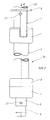
- Figur l schematisiert gezeichnete Seitenansicht eines Krankenhausbettes mit einer Aufrichtevorrichtung nach der Erfindung,
- Figur 2: Seitenansicht der Halterung für das Ovalrohr,
- Figur 3: Stirnansicht der Halterung in Richtung des Pfeiles III in Figur 2,
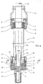
- Figur 4: Längsschnitt durch die Halterung nach Figur 2,
- Figur 5: Schnitt durch den oberen Lagertopf,
- Figur 6: Schnitt gemäss der Linie VI-VI in Figur 5,
- Figur 7: Schnitt durch den unteren Lagertopf gemäss der Linie VII-VII in Figur 4,
- Figur 8: Schnitt durch das mit dem Ovalrohr verbundene Kupplungsteil.
- Das in Figur l gezeigte Krankenhausbett 25 besteht in bekannter Weise aus einem Liegerahmen 28, an dessen vorderem und hinterem Ende jeweils ein Fußgestell 26 und ein Kopfgestell 27 angeordnet sind. Am Kopfgestell 27 ist ein Querholm 32 angebracht, an dem eine obere Einhängevorrichtung 33 für eine Halterung 34 vorgesehen ist. Im Abstand dazu ist im unteren Teil des Kopfgestells 27 eine Führungsplatte 3l vorgesehen, in welchem die Halterung 34 mit einem unteren, axialen Futterrohr 6 (vergl. Fig. 2) eingreift.
- In der Halterung 34 ist in den Pfeilrichtungen 47 verdrehbar und festlegbar ein Ovalrohr 3O gelagert, an dessen horizontalem Teil 45 ein dreiecksförmiger Handgriff 46 angeordnet ist.
- Die gesamte Aufrichtevorrichtung 29 besteht also aus dem Handgriff 46, dem Ovalrohr 3O und der zugeordneten Halterung 34.
- Die Halterung 34 ist gemäss Figur 2 leicht lösbar mit dem Kopfgestell 27 des Krankenhausbettes 25 dadurch verbunden, indem an der oberen Seite der Halterung 34 eine Verdrehsicherung 8 angeordnet ist, die aus einem umlaufenden Ring besteht, an dem unterhalb einwärts gerichtete, zueinander fluchtende Bolzen 23 angeordnet sind. Diese Bolzen werden in die Einhängevorrichtung 33 eingehängt, wobei gleichzeitig das Futterrohr 6 durch eine zugeordnete Ausnehmung in der unteren Tragplatte 3l eingreift. Auf diese Weise ist die Halterung 34 leicht lösbar am Kopfgestell 27 angeordnet, und es bedarf keiner Umrüstung bereits vorhandener Krankenhausbetten 25, denn die beschriebenen Halterungen 33,3l sind bereits schon an herkömmlichen Krankenhausbetten vorhanden.
- Von der Verdrehsicherung 8 abwärts erstreckt sich noch gemäss Figur 2 ein Haltebügel 7, der mit der Außenseite des oberen Lagertopfes l verschweisst ist; dieser trägt die gesamte Anordnung und schont gegen Verdrehung.
- An der Unterseite des Lagertopfes l setzt ein Distanzrohr 2 an, welches mit seinem gegenüberliegenden Ende mit dem unteren Lagertopf 4 verbunden ist. Der untere Lagertopf 4 wird von einem Deckel 3 abgeschlossen und er setzt sich nach unten in einen axialen Lagerwellensitz 5 fort, der schließlich in ein Futterrohr 6 mündet, welches in der vorher beschriebenen Weise lösbar in der Führungsplatte 3l am Kopfgestell 27 des Krankenhausbettes 25 eingesetzt wird.
- Die Figur 3 zeigt, daß das Ovalrohr 3O formschlüssig in eine zugeordnete rechteckförmige Ausnehmung eingesetzt ist, wobei der Außenumfang des Ovalrohres sich in die diagonal einander gegenüberliegenden, abgerundeten Ausnehmungen im oberen Lagertopf l einschmiegen.
- Der obere Lagertopf besteht gemäss Figur 4,5 und 6 aus einem oberen Schutzdeckel 9, der auf das becherförmige Unterteil dieses Lagertopfes l aufgesetzt ist. Im Unterteil dieses Lagertopfes l ist ein äußerer Lagerring lO vorgesehen, der an seiner Innenseite eine Kugelbüchse ll mit darin angeordneten Kugeln trägt, die an ihrer Innenseite an einem inneren Lagerring l4 abrollen. Der innere Lagerring l4 wird wiederum von einer inneren Ovalfutterbüchse l3 aufgenommen, und die gesamte Anordnung ist unten auf einem Kunststoffring l2 am Boden des becherförmigen Unterteils des Lagertopfes l gelagert.
- Gemäss Figur 6 ist das Ovalrohr 3O zwar drehfest, jedoch axial verschiebbar, in dem Ovallager l3 gelagert, welches sich mit Rippen 38 an der zugeordneten Innenfläche des inneren Lagerrings l4 abstützt. Das Ovalfutterrohr dreht und bewegt sich frei mit Lagerbuchse radial und axial.
- Mit der beschriebenen Anordnung können hohe Verkantungskräfte aufgenommen werden, die beim Angreifen eines entsprechenden Patientengwichts am Handgriff 46 auf den oberen Lagertopf l ausgeübt werden.
- Die gesamte Lageranordnung ist mit axialem Spiel im oberen Lagertopf l eingebaut. Aus diesem Grunde hat die untere Stirnseite des Schutzdeckels 9 einen axialen Abstand 36 zur oberen Stirnseite des zugeordneten Lageranordnung, die aus dem Lagerring lO, der Kugelbüchse ll , dem inneren Lagerring l4 und der Ovalfutterbüchse l3 besteht.
- Ebenso ist die Kugelbüchse ll zwischen der oberen Stirnseite des Lagerrings lO und dessen unterer Stirnseite mit einem axialen Spiel 37 verschiebbar.
- Gemäss Figur 4,7 und 8 ist im unteren Lagertopf 4 die erfindungsgemässe Kupplung angeordnet.
- Der untere Lagertopf 4 besteht aus einem becherförmigen Unterteil 5l, welches über ein Schraubgewinde mit einem zugeordneten Deckel 3 nach oben abgeschlossen wird.
- Zwischen dem becherförmigen Unterteil des oberen Lagertopfes l und dem Deckel 3 ist das Distanzrohr 2 aufgenommen.
- Das Ovalrohr 3O, welches sich axial und mit radialem Abstand durch das Distanzrohr 2 erstreckt, ist an seiner Unterseite drehfest mit einem Kupplungsteil l8 aus einem Metallmaterial, z.B. Grauguß, Stahlguß oder dgl. verbunden , wobei die untere Stirnseite des Ovalrohres in eine Ringnut 43 im Kupplungsteil l8 eingreift.
- In Figur 8 ist aus Vereinfachungsgründen diese Ringnut nicht gezeigt, denn es ist ebenso möglich, das Ovalrohr auf den oberen, konisch ausgebildeten, axialen Ansatz des Kupplungsteiles l8 aufzupressen.
- Das Kupplungsteil l8 weist einen unteren, als Konus 4O ausgebildeten, axialen Ansatz auf, der äußere Keilflächen 4l aufweist, welche die Kupplungsflächen zu zugeordneten Keilflächen 42 einer konischen Ausnehmung 48 von einer Bremsbacke l6 ausbilden.
- Die Bremsbacke l6 besteht gemäss Figur 4 und 7 aus einem zylinderförmigen Teil, welches in das Unterteil 5l des unteren Lagertopfes 4 eingesetzt ist.
- Im Ausführungsbeispiel nach Figur 7 besteht die Bremsbacke l6 aus vier voneinander durch radiale Schlitze 39 getrennte, segmentförmige Teile 49, die an ihrem Außenumfang mit einer umlaufenden Ringnut versehen ist, in welche eine Spannfeder 2O eingelegt ist. Durch die Spannfeder 2O werden die Teile 49 zusammengehalten und in radialer Richtung nach innen vorgespannt. Alle Teile bilden zusammen eine konische Ausnehmung 48, an deren Innenseite die vorher erwähnten Keilflächen 42 angeordnet sind, die mit den zugeordneten Keilflächen 4l des Kupplungsteiles l8 zusammenwirken.
- Sobald nun das Ovalrohr 3O in axialer Richtung in Pfeilrichtung 52 (vergl. Figur l) nach unten bewegt wird, bewegt sich das untere Kupplungsteil l8 entgegen der Kraft einer Druckfeder 2l mit seinen Keilflächen 4l in die Ausnehmung 48 der Bremsbacke l6 hinein.
- Die Druckfeder 2l greift hierbei in eine Ausnehmung 52 des Kupplungsteils l8 ein und ist mit dem unteren Ende in einem Lagerwellensitz 5 gelagert, der gleichzeitig zur Halterung einer Lagerwelle l7 dient, auf welche die Druckfeder 2l drehbar und axial verschiebbar gelagert ist. Die Lagerwelle l7 wird im Lagerwellensitz 5 über Gewindestifte 22 drefest gehalten und greift im übrigen noch in das Futterrohr 6 ein.
- Die Oberseite der Lagerwelle l7 ist in zwei voneinander beabstandeten Gleitlagerbuchsen l9,35 drehbar im Kupplungsteil l8 gelagert.
- Mit der axialen Verschiebung des Ovalrohres 3O in Pfeilrichutng 53 gleiten die Keilflächen 4l,42 von Kupplungsteil l8 und Ausnehmung 48 aneinander und die segmentförmigen Teile 49 der Bremsbacke l6 werden radial entgegen der Kraft der Spannfeder 2O nach außen verschoben und treffen sich an der geriffelten Innenfläche des Unterteils 5l des unteren Lagertopfes 4.
- Damit können jetzt hohe Verdrehkräfte arretiert werden, denn durch die großflächige Anlage von einander zugeordneten Keilflächen 4l,42 einerseits und durch die großflächige Anlage des Außenumfangs der segmentförmigen Teile 49 an der geriffelten Innenfläche des Unterteils 5l ergibt sich eine kraftschlüssige Verspannung der genannten Teile im Unterteil 5l.
- Wesentlich hierbei ist, daß die Keilflächen 4l,42 so angeschrägt sind, daß es nicht zu einer Selbstklemmung kommen kann. D.h. unter der Kraft der Druckfeder 2l ist die beschriebene Kupplung selbsttätig ausrückbar, wodurch das Ovalrohr 3O in Gegenrichtung zur Pfeilrichtung 53 nach oben geschoben wird und die segmentförmigen Teile 49 der Bremsbacke l6 über die Spannfeder 2O wieder radial einwärts sich bewegen.
- Um zu vermeiden, daß beim Ausrücken der Kupplung die Bremsbacken l6 in Gegenrichtung zur eingezeichneten Pfeilrichtung 53 nach oben mitgenommen werden, ist ein Abstreifer l5 vorgesehen, der als umlaufender Ring auf der Bremsbacke l6 aufsitzt und mit seiner Oberseite einen Abstand 5O zur Unterseite des Deckels 3 bildet.
- Damit kann sich die Bremsbacke l6 nur um das Maß des Abstandes 5O in axialer Richtung im unteren Lagertopf 4 bewegen.
- Der untere Lagertopf ist einfach zu öffnen, weil der Deckel 3 mit einem entsprechenden Gewinde 44 auf dem Unterteil 5l aufgeschraubt ist und mittels Kleber fixiert, d.h. drehfest gemacht ist.
- Die vorliegende Erfindung ist nicht auf die Verwendung eines Ovalrohres beschränkt; sie kann genauso beispielsweise mit einem Rundrohr realisiert werden, sofern die entsprechenden Lager rundprofilierte Anpassungen aufweisen. Andere Profilformen, wie Rechteck- oder Viereck-Profile, sind ebenfalls möglich. Die Anordnung ist direkt bei herkömmlichen Bettgalgen einsetzbar und kann ohne Veränderung der bestehenden Vorrichtungen am Bett eingehängt werden.
- l oberer Lagertopf
- 2 Distanzrohr
- 3 Deckel
- 4 unterer Lagertopf
- 5 Lagerwellensitz
- 6 Futterrohr
- 7 Haltebügel
- 8 Verdrehsicherung
- 9 Schutzdeckel
- lO Lagerring
- ll Kugelbüchse
- l2 Kunststoffring
- l3 Ovalfutterbüchse
- l4 Lagerring
- l5 Abstreifer
- l6 Bremsbacken
- l7 Lagerwelle
- l8 Kupplunsteil
- l9 Gleitlagerbuchse
- 2O Spannfeder
- 2l Druckfeder
- 22 Gewindestift
- 23 Bolzen
- 25 Krankenbett
- 26 Fußgestell
- 27 Kopfgestell
- 28 Liegerahmen
- 29 Aufrichtevorrichtung
- 3O Ovalrohr
- 3l Führungsplatte
- 32 Querholm
- 33 Einhängevorrichtung
- 34 Halterung
- 35 Gleitlagerbuchse
- 36 Abstand
- 37 Spiel
- 38 Rippe (Ovallager 13)
- 39 Schlitz (Bremsbacke 16)
- 4O Konus
- 4l Keilflächen (Konus 40)
- 42 Keilflächen (Ausnehmung 48)
- 43 Ringnut
- 44 Gewinde
- 45 Teil
- 46 Handgriff
- 47 Pfeilrichtung
- 48 konische Ausnehmung
- 49 Teil (Bremsbacke 16)
- 5O Abstand
- 5l Unterteil (Lagertopf 4)
- 52 Ausnehmung
- 53 Pfeilrichtung
Claims (7)
Priority Applications (1)
| Application Number | Priority Date | Filing Date | Title |
|---|---|---|---|
| AT86115666T ATE43239T1 (de) | 1985-11-13 | 1986-11-12 | Aufrichtevorrichtung fuer die anbringung an krankenhausbetten. |
Applications Claiming Priority (2)
| Application Number | Priority Date | Filing Date | Title |
|---|---|---|---|
| DE19853540302 DE3540302A1 (de) | 1985-11-13 | 1985-11-13 | Aufrichtevorrichtung fuer die anbringung an krankenhausbetten |
| DE3540302 | 1985-11-13 |
Publications (3)
| Publication Number | Publication Date |
|---|---|
| EP0222375A2 true EP0222375A2 (de) | 1987-05-20 |
| EP0222375A3 EP0222375A3 (en) | 1987-11-11 |
| EP0222375B1 EP0222375B1 (de) | 1989-05-24 |
Family
ID=6285915
Family Applications (1)
| Application Number | Title | Priority Date | Filing Date |
|---|---|---|---|
| EP86115666A Expired EP0222375B1 (de) | 1985-11-13 | 1986-11-12 | Aufrichtevorrichtung für die Anbringung an Krankenhausbetten |
Country Status (6)
| Country | Link |
|---|---|
| US (1) | US4847930A (de) |
| EP (1) | EP0222375B1 (de) |
| AT (1) | ATE43239T1 (de) |
| DE (2) | DE3540302A1 (de) |
| ES (1) | ES2009766B3 (de) |
| GR (1) | GR3000137T3 (de) |
Cited By (1)
| Publication number | Priority date | Publication date | Assignee | Title |
|---|---|---|---|---|
| EP0324237B1 (de) * | 1988-01-15 | 1993-06-09 | HILL-ROM COMPANY, INC. (an Indiana corporation) | Krankenhausbett mit drehbarem Kopfende |
Families Citing this family (14)
| Publication number | Priority date | Publication date | Assignee | Title |
|---|---|---|---|---|
| US4932090A (en) * | 1989-04-12 | 1990-06-12 | Johansson Paul J | Movable support bar |
| NL1001240C2 (nl) * | 1995-09-19 | 1997-03-20 | Prevas Ergonomie B V | Samenstel van een bed en een inrichting voor bewegings-ondersteuning bij het in of uit een bed bewegen door een persoon. |
| US6357064B1 (en) * | 2000-12-20 | 2002-03-19 | Donald Totsky | Assist device for disabled persons |
| US7188858B2 (en) * | 2002-04-24 | 2007-03-13 | Graco Children's Products Inc. | Foldable stroller |
| AU2003291215A1 (en) * | 2002-11-14 | 2004-06-03 | Adriaan Jacobus Nigrini | Spinal problem recovery aid |
| AU2003299869A1 (en) * | 2002-12-26 | 2004-07-29 | Gendron, Inc. | Bariatric patient management system |
| US7451509B2 (en) * | 2003-10-17 | 2008-11-18 | Jordan Dawes | Enhancer device for enhancing the utility of a user's bed |
| US20060130238A1 (en) * | 2004-07-16 | 2006-06-22 | Robyn Smith | Bed side rail method and apparatus |
| US7536738B2 (en) * | 2005-02-17 | 2009-05-26 | Hill-Rom Services, Inc. | Patient helper apparatus |
| US8607378B2 (en) | 2010-03-09 | 2013-12-17 | Hill-Rom Services, Inc. | Caregiver assist device |
| US8756735B2 (en) | 2011-02-08 | 2014-06-24 | Hill-Rom Services, Inc. | Patient helper with egress handle |
| EP3108866B1 (de) | 2015-06-24 | 2019-10-30 | Hill-Rom S.A.S. | Patientenpositionierungsvorrichtung und -verfahren |
| US10238562B2 (en) * | 2016-02-23 | 2019-03-26 | Hill-Rom Sas | Unit for providing assistance or services to a patient |
| EP3738571A1 (de) | 2019-05-16 | 2020-11-18 | Hill-Rom Services, Inc. | Vorrichtung zur aufrüstung eines heimbetts mit einem ausrüstungsträger |
Family Cites Families (15)
| Publication number | Priority date | Publication date | Assignee | Title |
|---|---|---|---|---|
| DE7332718U (de) * | 1973-11-29 | Bremshey Ag | Schwenkbarer Bettgalgen | |
| US1849102A (en) * | 1928-07-14 | 1932-03-15 | Gerald R Livergood | Slip bushing |
| US2010284A (en) * | 1933-08-15 | 1935-08-06 | Baash Ross Tool Co | Casing head |
| FR1378935A (fr) * | 1963-09-19 | 1964-11-20 | Nouvelle Soc Mirima | Supports télescopiques perfectionnés, notamment pour sièges et ensembles munis deces supports |
| GB1138172A (en) * | 1966-05-17 | 1968-12-27 | Evertaut Ltd | Seats of adjustable height |
| DE2152256A1 (de) * | 1971-10-20 | 1973-05-03 | Demag Ag | Kegelreibungsbremse |
| US3776387A (en) * | 1972-02-28 | 1973-12-04 | B Brent | Portable stand with magnetic bar surgical instrument holder for use on an operating cart or table |
| US3765053A (en) * | 1972-08-28 | 1973-10-16 | Magnavox Co | Friction support for lids |
| DE2458838A1 (de) * | 1974-12-12 | 1976-06-16 | Harry Dipl Ing Hammler | Einbeinstativ fuer film- und fotokameras |
| US4113222A (en) * | 1977-05-31 | 1978-09-12 | Frinzel Jerry C | Intravenous pole |
| DE3118449A1 (de) * | 1981-05-09 | 1982-12-02 | Sitema Gesellschaft für Sicherheitstechnik und Maschinenbau mbH, 7500 Karlsruhe | "klemmvorrichtung" |
| US4445660A (en) * | 1982-04-09 | 1984-05-01 | Karapita Alexander D | Adjustable suspension support |
| DE3502012A1 (de) * | 1982-06-02 | 1986-07-24 | Völker, geb. Mayer, Sigrid, 5014 Kerpen | Bettgestell, insbesondere fuer krankenhausbetten, mit einem gestellteil zugeordneter tragvorrichtung |
| DE3327320A1 (de) * | 1982-06-02 | 1985-02-07 | Völker, geb. Mayer, Sigrid, 5014 Kerpen | Bettgestell, insbesondere fuer krankenhausbett, mit einem gestellteil zugeordneter tragvorrichtung |
| DE3220783A1 (de) * | 1982-06-02 | 1983-12-08 | Völker, geb. Mayer, Sigrid, 5014 Kerpen | Bettgestell, insbesondere fuer krankenhausbett, mit einem gestellteil zugeordneter tragvorrichtung |
-
1985
- 1985-11-13 DE DE19853540302 patent/DE3540302A1/de active Granted
-
1986
- 1986-11-12 DE DE8686115666T patent/DE3663447D1/de not_active Expired
- 1986-11-12 EP EP86115666A patent/EP0222375B1/de not_active Expired
- 1986-11-12 AT AT86115666T patent/ATE43239T1/de not_active IP Right Cessation
- 1986-11-12 ES ES86115666T patent/ES2009766B3/es not_active Expired
- 1986-11-13 US US06/929,791 patent/US4847930A/en not_active Expired - Fee Related
-
1989
- 1989-08-25 GR GR89400140T patent/GR3000137T3/el unknown
Cited By (1)
| Publication number | Priority date | Publication date | Assignee | Title |
|---|---|---|---|---|
| EP0324237B1 (de) * | 1988-01-15 | 1993-06-09 | HILL-ROM COMPANY, INC. (an Indiana corporation) | Krankenhausbett mit drehbarem Kopfende |
Also Published As
| Publication number | Publication date |
|---|---|
| DE3540302A1 (de) | 1987-05-14 |
| GR3000137T3 (en) | 1990-11-29 |
| EP0222375B1 (de) | 1989-05-24 |
| DE3663447D1 (en) | 1989-06-29 |
| ES2009766B3 (es) | 1989-10-16 |
| ATE43239T1 (de) | 1989-06-15 |
| EP0222375A3 (en) | 1987-11-11 |
| US4847930A (en) | 1989-07-18 |
| DE3540302C2 (de) | 1989-02-09 |
Similar Documents
| Publication | Publication Date | Title |
|---|---|---|
| DE69324405T2 (de) | Krankenhausbett | |
| DE3540302C2 (de) | ||
| DE69003574T2 (de) | Höheneinstellvorrichtung, insbesondere für Möbel. | |
| DE3531824A1 (de) | Lenkrolle | |
| EP3736459B1 (de) | Anschlagpunkt | |
| DE9109862U1 (de) | Scharnier mit Drehtopf | |
| EP0399280A2 (de) | Kupplungseinrichtung eines Hebezeuges für einen Behälter | |
| DE69625811T2 (de) | Wartungsstütze für eine ladebrücke | |
| EP0098482A2 (de) | Hub- bzw. Absetzvorrichtung für transportable Behälter, z.B. Container, Shelter, Wechselaufbauten oder dgl. | |
| DE69406934T2 (de) | Kabeltrommelgestell | |
| DE202009002130U1 (de) | Multifunktionsständer | |
| EP0462629A1 (de) | Behälter | |
| DE60310177T2 (de) | Gestell mit Gelenkvorrichtungen für Stützarme | |
| EP0697296A1 (de) | Hebe-und Transportvorrichtung für schwere Gegenstände | |
| EP1354790A1 (de) | Klapprunge mit Riegeleinrichtung | |
| DE2736733C2 (de) | Zusatzgerät für Schraubenspannvorrichtungen, vorzugsweise von Reaktordruckbehältern | |
| EP1475493B1 (de) | Höhenverstellung einer Podestplatte | |
| DE2736206C3 (de) | Umlaufende Gefäßfüllmaschine | |
| DE29702673U1 (de) | Federspanner zum Spannen von Schraubenfedern mit zwei Druckplatten | |
| EP0187388A2 (de) | Höhenverstellbares Abstützgerät, insbesondere Sattelaufliegerstütze | |
| DE19931758C2 (de) | Trageeinrichtung zum Heben und Senken von Lasten | |
| AT10691U1 (de) | Ladekran mit in transportstellung bringbarem lastaufnahmemittel | |
| DE2917744A1 (de) | Heuwerbungsmaschine zum schwaden, wenden und zetten | |
| DE2422723A1 (de) | Fassheber | |
| DE4012586C1 (en) | Height-adjustable agricultural trailer coupling - has actuating shaft, protruding coaxially into guide bush, coupled to guide plates |
Legal Events
| Date | Code | Title | Description |
|---|---|---|---|
| PUAI | Public reference made under article 153(3) epc to a published international application that has entered the european phase |
Free format text: ORIGINAL CODE: 0009012 |
|
| AK | Designated contracting states |
Kind code of ref document: A2 Designated state(s): AT BE CH DE ES FR GB GR IT LI LU NL SE |
|
| 17P | Request for examination filed |
Effective date: 19870723 |
|
| PUAL | Search report despatched |
Free format text: ORIGINAL CODE: 0009013 |
|
| AK | Designated contracting states |
Kind code of ref document: A3 Designated state(s): AT BE CH DE ES FR GB GR IT LI LU NL SE |
|
| 17Q | First examination report despatched |
Effective date: 19880209 |
|
| RAP1 | Party data changed (applicant data changed or rights of an application transferred) |
Owner name: SPAETH GMBH & CO. KG STAHLBAU-BIEGETECHNIK |
|
| GRAA | (expected) grant |
Free format text: ORIGINAL CODE: 0009210 |
|
| AK | Designated contracting states |
Kind code of ref document: B1 Designated state(s): AT BE CH DE ES FR GB GR IT LI LU NL SE |
|
| REF | Corresponds to: |
Ref document number: 43239 Country of ref document: AT Date of ref document: 19890615 Kind code of ref document: T |
|
| REF | Corresponds to: |
Ref document number: 3663447 Country of ref document: DE Date of ref document: 19890629 |
|
| ITF | It: translation for a ep patent filed | ||
| ET | Fr: translation filed | ||
| GBT | Gb: translation of ep patent filed (gb section 77(6)(a)/1977) | ||
| PGFP | Annual fee paid to national office [announced via postgrant information from national office to epo] |
Ref country code: LU Payment date: 19891108 Year of fee payment: 4 |
|
| PGFP | Annual fee paid to national office [announced via postgrant information from national office to epo] |
Ref country code: AT Payment date: 19891115 Year of fee payment: 4 |
|
| PGFP | Annual fee paid to national office [announced via postgrant information from national office to epo] |
Ref country code: ES Payment date: 19891121 Year of fee payment: 4 |
|
| PGFP | Annual fee paid to national office [announced via postgrant information from national office to epo] |
Ref country code: FR Payment date: 19891124 Year of fee payment: 4 |
|
| PGFP | Annual fee paid to national office [announced via postgrant information from national office to epo] |
Ref country code: SE Payment date: 19891128 Year of fee payment: 4 |
|
| PG25 | Lapsed in a contracting state [announced via postgrant information from national office to epo] |
Ref country code: LU Free format text: LAPSE BECAUSE OF NON-PAYMENT OF DUE FEES Effective date: 19891130 |
|
| PGFP | Annual fee paid to national office [announced via postgrant information from national office to epo] |
Ref country code: NL Payment date: 19891130 Year of fee payment: 4 Ref country code: BE Payment date: 19891130 Year of fee payment: 4 |
|
| PGFP | Annual fee paid to national office [announced via postgrant information from national office to epo] |
Ref country code: CH Payment date: 19900130 Year of fee payment: 4 |
|
| PLBE | No opposition filed within time limit |
Free format text: ORIGINAL CODE: 0009261 |
|
| STAA | Information on the status of an ep patent application or granted ep patent |
Free format text: STATUS: NO OPPOSITION FILED WITHIN TIME LIMIT |
|
| 26N | No opposition filed | ||
| REG | Reference to a national code |
Ref country code: GR Ref legal event code: FG4A Free format text: 3000137 |
|
| PG25 | Lapsed in a contracting state [announced via postgrant information from national office to epo] |
Ref country code: AT Effective date: 19901112 |
|
| PGFP | Annual fee paid to national office [announced via postgrant information from national office to epo] |
Ref country code: GB Payment date: 19901112 Year of fee payment: 5 |
|
| PG25 | Lapsed in a contracting state [announced via postgrant information from national office to epo] |
Ref country code: SE Effective date: 19901113 Ref country code: ES Free format text: LAPSE BECAUSE OF NON-PAYMENT OF DUE FEES Effective date: 19901113 |
|
| PGFP | Annual fee paid to national office [announced via postgrant information from national office to epo] |
Ref country code: GR Payment date: 19901129 Year of fee payment: 5 |
|
| ITTA | It: last paid annual fee | ||
| PG25 | Lapsed in a contracting state [announced via postgrant information from national office to epo] |
Ref country code: LI Effective date: 19901130 Ref country code: CH Effective date: 19901130 Ref country code: BE Effective date: 19901130 |
|
| PGFP | Annual fee paid to national office [announced via postgrant information from national office to epo] |
Ref country code: DE Payment date: 19910124 Year of fee payment: 5 |
|
| BERE | Be: lapsed |
Owner name: SPATH G.M.B.H. & CO. K.G. STAHLBAU-BIEGETECHBIK Effective date: 19901130 |
|
| PG25 | Lapsed in a contracting state [announced via postgrant information from national office to epo] |
Ref country code: NL Effective date: 19910601 |
|
| NLV4 | Nl: lapsed or anulled due to non-payment of the annual fee | ||
| PG25 | Lapsed in a contracting state [announced via postgrant information from national office to epo] |
Ref country code: FR Effective date: 19910731 |
|
| REG | Reference to a national code |
Ref country code: CH Ref legal event code: PL |
|
| REG | Reference to a national code |
Ref country code: FR Ref legal event code: ST |
|
| PG25 | Lapsed in a contracting state [announced via postgrant information from national office to epo] |
Ref country code: GB Effective date: 19911112 |
|
| PG25 | Lapsed in a contracting state [announced via postgrant information from national office to epo] |
Ref country code: GR Free format text: THE PATENT HAS BEEN ANNULLED BY A DECISION OF A NATIONAL AUTHORITY Effective date: 19920531 |
|
| GBPC | Gb: european patent ceased through non-payment of renewal fee | ||
| PG25 | Lapsed in a contracting state [announced via postgrant information from national office to epo] |
Ref country code: DE Effective date: 19920801 |
|
| REG | Reference to a national code |
Ref country code: GR Ref legal event code: MM2A Free format text: 3000137 |
|
| EUG | Se: european patent has lapsed |
Ref document number: 86115666.9 Effective date: 19910705 |
|
| REG | Reference to a national code |
Ref country code: ES Ref legal event code: FD2A Effective date: 19911214 |
|
| PG25 | Lapsed in a contracting state [announced via postgrant information from national office to epo] |
Ref country code: IT Free format text: LAPSE BECAUSE OF NON-PAYMENT OF DUE FEES;WARNING: LAPSES OF ITALIAN PATENTS WITH EFFECTIVE DATE BEFORE 2007 MAY HAVE OCCURRED AT ANY TIME BEFORE 2007. THE CORRECT EFFECTIVE DATE MAY BE DIFFERENT FROM THE ONE RECORDED. Effective date: 20051112 |