EP0222375A2 - Dispositif de relèvement applicable à des lits d'hôpital - Google Patents
Dispositif de relèvement applicable à des lits d'hôpital Download PDFInfo
- Publication number
- EP0222375A2 EP0222375A2 EP86115666A EP86115666A EP0222375A2 EP 0222375 A2 EP0222375 A2 EP 0222375A2 EP 86115666 A EP86115666 A EP 86115666A EP 86115666 A EP86115666 A EP 86115666A EP 0222375 A2 EP0222375 A2 EP 0222375A2
- Authority
- EP
- European Patent Office
- Prior art keywords
- bearing
- holder
- oval
- coupling
- oval tube
- Prior art date
- Legal status (The legal status is an assumption and is not a legal conclusion. Google has not performed a legal analysis and makes no representation as to the accuracy of the status listed.)
- Granted
Links
- 230000008878 coupling Effects 0.000 claims abstract description 34
- 238000010168 coupling process Methods 0.000 claims abstract description 34
- 238000005859 coupling reaction Methods 0.000 claims abstract description 34
- 230000006835 compression Effects 0.000 claims description 8
- 238000007906 compression Methods 0.000 claims description 8
- 239000004033 plastic Substances 0.000 claims description 4
- 239000004952 Polyamide Substances 0.000 claims description 2
- 229920002647 polyamide Polymers 0.000 claims description 2
- HEMHJVSKTPXQMS-UHFFFAOYSA-M Sodium hydroxide Chemical compound [OH-].[Na+] HEMHJVSKTPXQMS-UHFFFAOYSA-M 0.000 claims 1
- 101100298222 Caenorhabditis elegans pot-1 gene Proteins 0.000 description 7
- 125000006850 spacer group Chemical group 0.000 description 4
- 230000001681 protective effect Effects 0.000 description 3
- 239000000725 suspension Substances 0.000 description 3
- 210000000078 claw Anatomy 0.000 description 2
- 101150038956 cup-4 gene Proteins 0.000 description 2
- 229910001018 Cast iron Inorganic materials 0.000 description 1
- 229910001208 Crucible steel Inorganic materials 0.000 description 1
- 230000006978 adaptation Effects 0.000 description 1
- 239000000853 adhesive Substances 0.000 description 1
- 230000001070 adhesive effect Effects 0.000 description 1
- 238000006073 displacement reaction Methods 0.000 description 1
- 239000000463 material Substances 0.000 description 1
- 239000002184 metal Substances 0.000 description 1
- 229910052751 metal Inorganic materials 0.000 description 1
- 239000007769 metal material Substances 0.000 description 1
Images


Classifications
-
- A—HUMAN NECESSITIES
- A61—MEDICAL OR VETERINARY SCIENCE; HYGIENE
- A61G—TRANSPORT, PERSONAL CONVEYANCES, OR ACCOMMODATION SPECIALLY ADAPTED FOR PATIENTS OR DISABLED PERSONS; OPERATING TABLES OR CHAIRS; CHAIRS FOR DENTISTRY; FUNERAL DEVICES
- A61G7/00—Beds specially adapted for nursing; Devices for lifting patients or disabled persons
- A61G7/05—Parts, details or accessories of beds
- A61G7/053—Aids for getting into, or out of, bed, e.g. steps, chairs, cane-like supports
- A61G7/0533—Lifting poles
Definitions
- the invention relates to an erection device for attachment to hospital beds according to the preamble of claim 1.
- Such an erecting device has become known, for example, with the subject of DE-OS 33 27 32O.
- Raising devices of this type are used in particular for freshly operated or handicapped patients, the patient lying in bed gripping the triangular-shaped handle with his hands and pulling up on it.
- the oval tube is pivotally mounted in the holder so that the patient can swing over the rotation of the oval tube in the holder to the edge of the bed by stopping at the handle.
- the coupling which prevents rotation, is intended to ensure that the pivotable oval tube is fixed in the holder in any pivot position. This prevents the oval tube from swinging out too far and, for example, from damaging objects standing next to the bed.
- the clutch consists of a dog clutch, which can be engaged against the spring force of a compression spring.
- a disadvantage of this arrangement is that it is not possible to lock this coupling in any intermediate positions, because only a certain angle of rotation can be locked by the tooth division of the intermeshing claw coupling.
- the invention has for its object to develop an erecting device of the type mentioned in such a way that it can be locked in any rotational position while avoiding early wear of the coupling.
- the invention is characterized in that the coupling consists of a coupling part which is connected in a rotationally fixed manner to the oval tube in the axial extension of the oval tube and which has a conical axial extension which is in an associated conical recess of a radially expandable brake shoe attacks, which can be pressed with its outer circumference non-positively to bear against the inside of a coupling pot receiving the coupling.
- a feature of the invention is therefore that the oval tube is connected in a rotationally fixed manner to an axial extension designed as a cone and can be axially engaged with this cone in an associated conical recess of a radially expandable brake shoe.
- the brake shoe consists of a plurality of segment-shaped parts which are separated from one another by radial slots, with an all-embracing tension spring being arranged in an annular groove on the outer circumference of the brake shoe.
- segment-shaped parts then come to rest with their outer circumference on the inside of a lower bearing pot, which is provided on the inside with a corrugation running in the axial direction, which acts as a friction-increasing surface for the outer surfaces of the brake shoe pressed against it.
- the coupling part which is connected to the oval tube in a rotationally fixed manner, consists of a metal part and the associated brake shoes consist of a polyamide plastic.
- the coupling part which is connected to the oval tube in a rotationally fixed manner, consists of a metal part and the associated brake shoes consist of a polyamide plastic.
- the hospital bed 25 shown in FIG. 1 consists in a known manner of a bed frame 28, at the front and rear end of which a foot frame 26 and a head frame 27 are arranged.
- a cross member 32 is attached to the head frame 27, on which an upper suspension device 33 for a holder 34 is provided.
- a guide plate 3l is provided in the lower part of the head frame 27, in which the holder 34 engages with a lower, axial casing tube 6 (see FIG. 2).
- An oval tube 30 is rotatably and fixably mounted in the holder 34 in the arrow directions 47, on the horizontal part 45 of which a triangular handle 46 is arranged.
- the entire lifting device 29 thus consists of the handle 46, the oval tube 30 and the associated holder 34.
- the holder 34 is easily detachably connected to the head frame 27 of the hospital bed 25 by arranging an anti-rotation device 8 on the upper side of the holder 34, which consists of an encircling ring on which bolts 23 which are directed inwards and below one another are arranged. These bolts are hooked into the suspension device 33, the casing tube 6 simultaneously engaging through an associated recess in the lower support plate 3l.
- the holder 34 is arranged in an easily detachable manner on the head frame 27, and there is no need to retrofit existing hospital beds 25, since the holders 33, 31l already described are already present on conventional hospital beds.
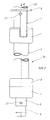
- FIG. 3 shows that the oval tube 30 is inserted in a form-fitting manner in an assigned rectangular recess, the outer circumference of the oval tube nestling into the diagonally opposite, rounded recesses in the upper bearing pot 1.
- the upper bearing pot consists of an upper protective cover 9 which is placed on the cup-shaped lower part of this bearing pot 1.
- An outer bearing ring 10 is provided in the lower part of this bearing pot 1, which carries on its inside a ball bushing 11 with balls arranged therein, which roll on its inside on an inner bearing ring 14.
- the inner bearing ring l4 is in turn received by an inner oval chuck l3, and the entire arrangement is supported at the bottom on a plastic ring l2 at the bottom of the cup-shaped lower part of the bearing pot l.
- the oval tube 30 is rotatably but axially displaceable in the oval bearing l3, which is supported by ribs 38 on the associated inner surface of the inner bearing ring l4.
- the oval casing tube rotates and moves freely with the bearing bush radially and axially.
- the entire bearing arrangement is with axial play in the upper bearing cup l built in.
- the lower end face of the protective cover 9 has an axial distance 36 to the upper end face of the associated bearing arrangement, which consists of the bearing ring 10, the ball bushing 11, the inner bearing ring 14 and the oval chuck bushing l3.
- the ball bushing 11 can be displaced with an axial play 37 between the upper end face of the bearing ring 10 and its lower end face.
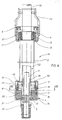
- the coupling according to the invention is arranged in the lower bearing pot 4.
- the lower bearing pot 4 consists of a cup-shaped lower part 5l, which is closed at the top by a screw thread with an associated cover 3.
- the spacer tube 2 is received between the cup-shaped lower part of the upper bearing pot 1 and the cover 3.
- a coupling part 18 made of a metal material, e.g. Cast iron, cast steel or the like.
- this annular groove is not shown in FIG. 8, because it is also possible to press the oval tube onto the upper, conically shaped, axial shoulder of the coupling part 18.
- the coupling part 18 has a lower cone 40 trained, axial approach, which has outer wedge surfaces 4l, which form the coupling surfaces to associated wedge surfaces 42 of a conical recess 48 of a brake shoe l6.
- the brake shoe 16 consists of a cylindrical part which is inserted into the lower part 5l of the lower bearing cup 4.
- the brake shoe 16 consists of four segment-shaped parts 49 which are separated from one another by radial slots 39 and which is provided on its outer circumference with a circumferential annular groove into which a tension spring 20 is inserted.
- the parts 49 are held together by the tension spring 20 and are biased inward in the radial direction. All parts together form a conical recess 48, on the inside of which the aforementioned wedge surfaces 42 are arranged, which interact with the associated wedge surfaces 4l of the coupling part 18.
- the compression spring 2l engages in a recess 52 of the coupling part l8 and is supported with the lower end in a bearing shaft seat 5, which at the same time serves to hold a bearing shaft l7 on which the compression spring 2l is rotatably and axially displaceably mounted.
- the bearing shaft 17 is held non-rotatably in the bearing shaft seat 5 by means of setscrews 22 and also engages in the casing 6.
- the top of the bearing shaft l7 is in two from each other spaced plain bearing bushes l9,35 rotatably mounted in the coupling part l8.
- the wedge surfaces 4l, 42 are chamfered so that self-clamping cannot occur. I.e. Under the force of the compression spring 2l, the clutch described can be disengaged automatically, as a result of which the oval tube 3O is pushed upward in the opposite direction to the arrow direction 53 and the segment-shaped parts 49 of the brake shoe l6 move radially inward again via the tension spring 2O.
- a stripper l5 is provided, which is seated as a circumferential ring on the brake shoe l6 and with its upper side a distance 50 to the bottom of the cover 3 forms.
- the lower storage pot is easy to open because the cover 3 is screwed onto the lower part 5l with a corresponding thread 44 and is fixed with adhesive, i.e. is made non-rotatable.
Landscapes
- Health & Medical Sciences (AREA)
- Nursing (AREA)
- Life Sciences & Earth Sciences (AREA)
- Animal Behavior & Ethology (AREA)
- General Health & Medical Sciences (AREA)
- Public Health (AREA)
- Veterinary Medicine (AREA)
- Invalid Beds And Related Equipment (AREA)
- Braking Arrangements (AREA)
Priority Applications (1)
| Application Number | Priority Date | Filing Date | Title |
|---|---|---|---|
| AT86115666T ATE43239T1 (de) | 1985-11-13 | 1986-11-12 | Aufrichtevorrichtung fuer die anbringung an krankenhausbetten. |
Applications Claiming Priority (2)
| Application Number | Priority Date | Filing Date | Title |
|---|---|---|---|
| DE3540302 | 1985-11-13 | ||
| DE19853540302 DE3540302A1 (de) | 1985-11-13 | 1985-11-13 | Aufrichtevorrichtung fuer die anbringung an krankenhausbetten |
Publications (3)
| Publication Number | Publication Date |
|---|---|
| EP0222375A2 true EP0222375A2 (fr) | 1987-05-20 |
| EP0222375A3 EP0222375A3 (en) | 1987-11-11 |
| EP0222375B1 EP0222375B1 (fr) | 1989-05-24 |
Family
ID=6285915
Family Applications (1)
| Application Number | Title | Priority Date | Filing Date |
|---|---|---|---|
| EP86115666A Expired EP0222375B1 (fr) | 1985-11-13 | 1986-11-12 | Dispositif de relèvement applicable à des lits d'hôpital |
Country Status (6)
| Country | Link |
|---|---|
| US (1) | US4847930A (fr) |
| EP (1) | EP0222375B1 (fr) |
| AT (1) | ATE43239T1 (fr) |
| DE (2) | DE3540302A1 (fr) |
| ES (1) | ES2009766B3 (fr) |
| GR (1) | GR3000137T3 (fr) |
Cited By (1)
| Publication number | Priority date | Publication date | Assignee | Title |
|---|---|---|---|---|
| EP0324237B1 (fr) * | 1988-01-15 | 1993-06-09 | HILL-ROM COMPANY, INC. (an Indiana corporation) | Lit d'hôpital avec chevet pivotant |
Families Citing this family (14)
| Publication number | Priority date | Publication date | Assignee | Title |
|---|---|---|---|---|
| US4932090A (en) * | 1989-04-12 | 1990-06-12 | Johansson Paul J | Movable support bar |
| NL1001240C2 (nl) * | 1995-09-19 | 1997-03-20 | Prevas Ergonomie B V | Samenstel van een bed en een inrichting voor bewegings-ondersteuning bij het in of uit een bed bewegen door een persoon. |
| US6357064B1 (en) * | 2000-12-20 | 2002-03-19 | Donald Totsky | Assist device for disabled persons |
| US7188858B2 (en) | 2002-04-24 | 2007-03-13 | Graco Children's Products Inc. | Foldable stroller |
| AU2003291215A1 (en) * | 2002-11-14 | 2004-06-03 | Adriaan Jacobus Nigrini | Spinal problem recovery aid |
| AU2003299869A1 (en) * | 2002-12-26 | 2004-07-29 | Gendron, Inc. | Bariatric patient management system |
| US7451509B2 (en) * | 2003-10-17 | 2008-11-18 | Jordan Dawes | Enhancer device for enhancing the utility of a user's bed |
| US20060130238A1 (en) * | 2004-07-16 | 2006-06-22 | Robyn Smith | Bed side rail method and apparatus |
| US7536738B2 (en) * | 2005-02-17 | 2009-05-26 | Hill-Rom Services, Inc. | Patient helper apparatus |
| US8607378B2 (en) | 2010-03-09 | 2013-12-17 | Hill-Rom Services, Inc. | Caregiver assist device |
| US8756735B2 (en) | 2011-02-08 | 2014-06-24 | Hill-Rom Services, Inc. | Patient helper with egress handle |
| EP3108866B1 (fr) | 2015-06-24 | 2019-10-30 | Hill-Rom S.A.S. | Procede et appareil de positionnement de patient |
| US10238562B2 (en) * | 2016-02-23 | 2019-03-26 | Hill-Rom Sas | Unit for providing assistance or services to a patient |
| EP3738571A1 (fr) | 2019-05-16 | 2020-11-18 | Hill-Rom Services, Inc. | Dispositif d'amélioration d'un lit résidentiel pour inclure un support d'équipement |
Family Cites Families (15)
| Publication number | Priority date | Publication date | Assignee | Title |
|---|---|---|---|---|
| DE7332718U (de) * | 1973-11-29 | Bremshey Ag | Schwenkbarer Bettgalgen | |
| US1849102A (en) * | 1928-07-14 | 1932-03-15 | Gerald R Livergood | Slip bushing |
| US2010284A (en) * | 1933-08-15 | 1935-08-06 | Baash Ross Tool Co | Casing head |
| FR1378935A (fr) * | 1963-09-19 | 1964-11-20 | Nouvelle Soc Mirima | Supports télescopiques perfectionnés, notamment pour sièges et ensembles munis deces supports |
| GB1138172A (en) * | 1966-05-17 | 1968-12-27 | Evertaut Ltd | Seats of adjustable height |
| DE2152256A1 (de) * | 1971-10-20 | 1973-05-03 | Demag Ag | Kegelreibungsbremse |
| US3776387A (en) * | 1972-02-28 | 1973-12-04 | B Brent | Portable stand with magnetic bar surgical instrument holder for use on an operating cart or table |
| US3765053A (en) * | 1972-08-28 | 1973-10-16 | Magnavox Co | Friction support for lids |
| DE2458838A1 (de) * | 1974-12-12 | 1976-06-16 | Harry Dipl Ing Hammler | Einbeinstativ fuer film- und fotokameras |
| US4113222A (en) * | 1977-05-31 | 1978-09-12 | Frinzel Jerry C | Intravenous pole |
| DE3118449A1 (de) * | 1981-05-09 | 1982-12-02 | Sitema Gesellschaft für Sicherheitstechnik und Maschinenbau mbH, 7500 Karlsruhe | "klemmvorrichtung" |
| US4445660A (en) * | 1982-04-09 | 1984-05-01 | Karapita Alexander D | Adjustable suspension support |
| DE3327320A1 (de) * | 1982-06-02 | 1985-02-07 | Völker, geb. Mayer, Sigrid, 5014 Kerpen | Bettgestell, insbesondere fuer krankenhausbett, mit einem gestellteil zugeordneter tragvorrichtung |
| DE3502012A1 (de) * | 1982-06-02 | 1986-07-24 | Völker, geb. Mayer, Sigrid, 5014 Kerpen | Bettgestell, insbesondere fuer krankenhausbetten, mit einem gestellteil zugeordneter tragvorrichtung |
| DE3220783A1 (de) * | 1982-06-02 | 1983-12-08 | Völker, geb. Mayer, Sigrid, 5014 Kerpen | Bettgestell, insbesondere fuer krankenhausbett, mit einem gestellteil zugeordneter tragvorrichtung |
-
1985
- 1985-11-13 DE DE19853540302 patent/DE3540302A1/de active Granted
-
1986
- 1986-11-12 ES ES86115666T patent/ES2009766B3/es not_active Expired
- 1986-11-12 DE DE8686115666T patent/DE3663447D1/de not_active Expired
- 1986-11-12 EP EP86115666A patent/EP0222375B1/fr not_active Expired
- 1986-11-12 AT AT86115666T patent/ATE43239T1/de not_active IP Right Cessation
- 1986-11-13 US US06/929,791 patent/US4847930A/en not_active Expired - Fee Related
-
1989
- 1989-08-25 GR GR89400140T patent/GR3000137T3/el unknown
Cited By (1)
| Publication number | Priority date | Publication date | Assignee | Title |
|---|---|---|---|---|
| EP0324237B1 (fr) * | 1988-01-15 | 1993-06-09 | HILL-ROM COMPANY, INC. (an Indiana corporation) | Lit d'hôpital avec chevet pivotant |
Also Published As
| Publication number | Publication date |
|---|---|
| GR3000137T3 (en) | 1990-11-29 |
| ES2009766B3 (es) | 1989-10-16 |
| ATE43239T1 (de) | 1989-06-15 |
| DE3540302C2 (fr) | 1989-02-09 |
| DE3540302A1 (de) | 1987-05-14 |
| US4847930A (en) | 1989-07-18 |
| EP0222375A3 (en) | 1987-11-11 |
| EP0222375B1 (fr) | 1989-05-24 |
| DE3663447D1 (en) | 1989-06-29 |
Similar Documents
| Publication | Publication Date | Title |
|---|---|---|
| DE69324405T2 (de) | Krankenhausbett | |
| EP0222375A2 (fr) | Dispositif de relèvement applicable à des lits d'hôpital | |
| DE69003574T2 (de) | Höheneinstellvorrichtung, insbesondere für Möbel. | |
| DE3531824A1 (de) | Lenkrolle | |
| EP3736459B1 (fr) | Point d'ancrage | |
| DE9109862U1 (de) | Scharnier mit Drehtopf | |
| EP0399280A2 (fr) | Dispositif d'accouplement d'un moyen de levage à un conteneur | |
| DE69625811T2 (de) | Wartungsstütze für eine ladebrücke | |
| DD150336A5 (de) | Heuwerbungsmaschine zum schwaden,wenden und zetten | |
| EP0098482A2 (fr) | Dispositif de levage ou de dépose pour des réceptacles transportables, par exemple conteneurs, abris, structures amovibles ou semblables | |
| DE69406934T2 (de) | Kabeltrommelgestell | |
| EP0462629A1 (fr) | Réceptacle | |
| DE60310177T2 (de) | Gestell mit Gelenkvorrichtungen für Stützarme | |
| EP0697296A1 (fr) | Dispositif de levage et de transport pour objets lourds | |
| EP1354790A1 (fr) | Rancher pliant avec dispositif de verrouillage | |
| DE2736733C2 (de) | Zusatzgerät für Schraubenspannvorrichtungen, vorzugsweise von Reaktordruckbehältern | |
| DE2736206C3 (de) | Umlaufende Gefäßfüllmaschine | |
| DE29702673U1 (de) | Federspanner zum Spannen von Schraubenfedern mit zwei Druckplatten | |
| DE2435516A1 (de) | Vorrichtung zum heben und bewegen eines gegenstandes | |
| EP0187388A2 (fr) | Dispositif d'appui réglable en hauteur, notamment jambe d'appui de semi-remorque | |
| DE19931758C2 (de) | Trageeinrichtung zum Heben und Senken von Lasten | |
| AT10691U1 (de) | Ladekran mit in transportstellung bringbarem lastaufnahmemittel | |
| DE2917744A1 (de) | Heuwerbungsmaschine zum schwaden, wenden und zetten | |
| DE2448916C2 (de) | Entleerungsvorrichtung, insbesondere an MüNsammelbehältern, für GroßraummüllgefäBe mit zwei Schwenkarmen | |
| DE2422723A1 (de) | Fassheber |
Legal Events
| Date | Code | Title | Description |
|---|---|---|---|
| PUAI | Public reference made under article 153(3) epc to a published international application that has entered the european phase |
Free format text: ORIGINAL CODE: 0009012 |
|
| AK | Designated contracting states |
Kind code of ref document: A2 Designated state(s): AT BE CH DE ES FR GB GR IT LI LU NL SE |
|
| 17P | Request for examination filed |
Effective date: 19870723 |
|
| PUAL | Search report despatched |
Free format text: ORIGINAL CODE: 0009013 |
|
| AK | Designated contracting states |
Kind code of ref document: A3 Designated state(s): AT BE CH DE ES FR GB GR IT LI LU NL SE |
|
| 17Q | First examination report despatched |
Effective date: 19880209 |
|
| RAP1 | Party data changed (applicant data changed or rights of an application transferred) |
Owner name: SPAETH GMBH & CO. KG STAHLBAU-BIEGETECHNIK |
|
| GRAA | (expected) grant |
Free format text: ORIGINAL CODE: 0009210 |
|
| AK | Designated contracting states |
Kind code of ref document: B1 Designated state(s): AT BE CH DE ES FR GB GR IT LI LU NL SE |
|
| REF | Corresponds to: |
Ref document number: 43239 Country of ref document: AT Date of ref document: 19890615 Kind code of ref document: T |
|
| REF | Corresponds to: |
Ref document number: 3663447 Country of ref document: DE Date of ref document: 19890629 |
|
| ITF | It: translation for a ep patent filed | ||
| ET | Fr: translation filed | ||
| GBT | Gb: translation of ep patent filed (gb section 77(6)(a)/1977) | ||
| PGFP | Annual fee paid to national office [announced via postgrant information from national office to epo] |
Ref country code: LU Payment date: 19891108 Year of fee payment: 4 |
|
| PGFP | Annual fee paid to national office [announced via postgrant information from national office to epo] |
Ref country code: AT Payment date: 19891115 Year of fee payment: 4 |
|
| PGFP | Annual fee paid to national office [announced via postgrant information from national office to epo] |
Ref country code: ES Payment date: 19891121 Year of fee payment: 4 |
|
| PGFP | Annual fee paid to national office [announced via postgrant information from national office to epo] |
Ref country code: FR Payment date: 19891124 Year of fee payment: 4 |
|
| PGFP | Annual fee paid to national office [announced via postgrant information from national office to epo] |
Ref country code: SE Payment date: 19891128 Year of fee payment: 4 |
|
| PG25 | Lapsed in a contracting state [announced via postgrant information from national office to epo] |
Ref country code: LU Free format text: LAPSE BECAUSE OF NON-PAYMENT OF DUE FEES Effective date: 19891130 |
|
| PGFP | Annual fee paid to national office [announced via postgrant information from national office to epo] |
Ref country code: NL Payment date: 19891130 Year of fee payment: 4 Ref country code: BE Payment date: 19891130 Year of fee payment: 4 |
|
| PGFP | Annual fee paid to national office [announced via postgrant information from national office to epo] |
Ref country code: CH Payment date: 19900130 Year of fee payment: 4 |
|
| PLBE | No opposition filed within time limit |
Free format text: ORIGINAL CODE: 0009261 |
|
| STAA | Information on the status of an ep patent application or granted ep patent |
Free format text: STATUS: NO OPPOSITION FILED WITHIN TIME LIMIT |
|
| 26N | No opposition filed | ||
| REG | Reference to a national code |
Ref country code: GR Ref legal event code: FG4A Free format text: 3000137 |
|
| PG25 | Lapsed in a contracting state [announced via postgrant information from national office to epo] |
Ref country code: AT Effective date: 19901112 |
|
| PGFP | Annual fee paid to national office [announced via postgrant information from national office to epo] |
Ref country code: GB Payment date: 19901112 Year of fee payment: 5 |
|
| PG25 | Lapsed in a contracting state [announced via postgrant information from national office to epo] |
Ref country code: SE Effective date: 19901113 Ref country code: ES Free format text: LAPSE BECAUSE OF NON-PAYMENT OF DUE FEES Effective date: 19901113 |
|
| PGFP | Annual fee paid to national office [announced via postgrant information from national office to epo] |
Ref country code: GR Payment date: 19901129 Year of fee payment: 5 |
|
| ITTA | It: last paid annual fee | ||
| PG25 | Lapsed in a contracting state [announced via postgrant information from national office to epo] |
Ref country code: LI Effective date: 19901130 Ref country code: CH Effective date: 19901130 Ref country code: BE Effective date: 19901130 |
|
| PGFP | Annual fee paid to national office [announced via postgrant information from national office to epo] |
Ref country code: DE Payment date: 19910124 Year of fee payment: 5 |
|
| BERE | Be: lapsed |
Owner name: SPATH G.M.B.H. & CO. K.G. STAHLBAU-BIEGETECHBIK Effective date: 19901130 |
|
| PG25 | Lapsed in a contracting state [announced via postgrant information from national office to epo] |
Ref country code: NL Effective date: 19910601 |
|
| NLV4 | Nl: lapsed or anulled due to non-payment of the annual fee | ||
| PG25 | Lapsed in a contracting state [announced via postgrant information from national office to epo] |
Ref country code: FR Effective date: 19910731 |
|
| REG | Reference to a national code |
Ref country code: CH Ref legal event code: PL |
|
| REG | Reference to a national code |
Ref country code: FR Ref legal event code: ST |
|
| PG25 | Lapsed in a contracting state [announced via postgrant information from national office to epo] |
Ref country code: GB Effective date: 19911112 |
|
| PG25 | Lapsed in a contracting state [announced via postgrant information from national office to epo] |
Ref country code: GR Free format text: THE PATENT HAS BEEN ANNULLED BY A DECISION OF A NATIONAL AUTHORITY Effective date: 19920531 |
|
| GBPC | Gb: european patent ceased through non-payment of renewal fee | ||
| PG25 | Lapsed in a contracting state [announced via postgrant information from national office to epo] |
Ref country code: DE Effective date: 19920801 |
|
| REG | Reference to a national code |
Ref country code: GR Ref legal event code: MM2A Free format text: 3000137 |
|
| EUG | Se: european patent has lapsed |
Ref document number: 86115666.9 Effective date: 19910705 |
|
| REG | Reference to a national code |
Ref country code: ES Ref legal event code: FD2A Effective date: 19911214 |
|
| PG25 | Lapsed in a contracting state [announced via postgrant information from national office to epo] |
Ref country code: IT Free format text: LAPSE BECAUSE OF NON-PAYMENT OF DUE FEES;WARNING: LAPSES OF ITALIAN PATENTS WITH EFFECTIVE DATE BEFORE 2007 MAY HAVE OCCURRED AT ANY TIME BEFORE 2007. THE CORRECT EFFECTIVE DATE MAY BE DIFFERENT FROM THE ONE RECORDED. Effective date: 20051112 |