EP0222387A2 - Verfahren zur Erzeugung einer Entwurfreferenz und Gerät dafür - Google Patents
Verfahren zur Erzeugung einer Entwurfreferenz und Gerät dafür Download PDFInfo
- Publication number
- EP0222387A2 EP0222387A2 EP86115709A EP86115709A EP0222387A2 EP 0222387 A2 EP0222387 A2 EP 0222387A2 EP 86115709 A EP86115709 A EP 86115709A EP 86115709 A EP86115709 A EP 86115709A EP 0222387 A2 EP0222387 A2 EP 0222387A2
- Authority
- EP
- European Patent Office
- Prior art keywords
- design object
- design
- interference check
- information
- check element
- Prior art date
- Legal status (The legal status is an assumption and is not a legal conclusion. Google has not performed a legal analysis and makes no representation as to the accuracy of the status listed.)
- Granted
Links
Images


Classifications
-
- G—PHYSICS
- G06—COMPUTING OR CALCULATING; COUNTING
- G06F—ELECTRIC DIGITAL DATA PROCESSING
- G06F15/00—Digital computers in general; Data processing equipment in general
-
- G—PHYSICS
- G06—COMPUTING OR CALCULATING; COUNTING
- G06F—ELECTRIC DIGITAL DATA PROCESSING
- G06F30/00—Computer-aided design [CAD]
- G06F30/10—Geometric CAD
- G06F30/13—Architectural design, e.g. computer-aided architectural design [CAAD] related to design of buildings, bridges, landscapes, production plants or roads
Definitions
- the present invention relates to a method for making of design reference and an apparatus therefor, and more particularly to a method for making of design reference and an apparatus therefor suitable for interactively and comparatively checking validity of a layout plan of components of a design object.
- An apparatus for making of design reference (hereafter referred to as a CAD apparatus) comprises a display screen on which a design object is to be displayed and an input device for generating coordinate data based on designation of a point on the display screen to display a point, line or characters at the point designated by a designer and write a coordinate of that point and the displayed data into a memory by using an interactive technique.
- a CAD apparatus comprises a display screen on which a design object is to be displayed and an input device for generating coordinate data based on designation of a point on the display screen to display a point, line or characters at the point designated by a designer and write a coordinate of that point and the displayed data into a memory by using an interactive technique.
- a data of a design object is converted to an image data to display it on a display screen, and comparative checking of the design object is done by visually watching the data on the display.
- a CAD apparatus disclosed in JP-A-59-17382 scaled orthogonal lines are displayed on a display screen. An operator watches the orthogonal lines to visually measure a distance between two points on the screen.
- a CAD apparatus disclosed in JP-A-60-3791 recognizes a vector related to a point on a display screen which an operator picked.
- the present invention is characterized by the steps of preparing first information for graphically displaying a structure of a designated design object based on a selected data, preparing second information for graphically displaying a designated interference check element which simulates an article or a man moving in an area in which a real design object is to be installed, and displaying patterns of the design object and the interference check element based on the first and second information.
- the interference check element moves or need be moved in an area in which a real machine - (manufactured real machine of a design object) is to be installed, or in the real unit, and it simulates the movement in the area of the real unit installation or in the real unit in order to check presence or absence of interference with a component of the real unit in the movement in the area of the real unit installation.
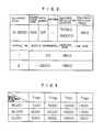
- a design object data memory 7 stores data of a design object corresponding to a menu item shown in Fig. 4 and coordinate data of menu items shown in Fig. 5, that is, the design object.
- the design object data memory 7 further stores start point and end point coordinates of the design object, a coordinate of a branch end point of a branch line (see Fig. 6), and data of connectivity of components of the design object (see Fig. 7).
- a standard pattern shape data memory 8 stores standard pattern shape data of the components of the design object, as shown in Fig. 8.
- An operator enters a code of a design object area in which the design object is to be located, from the input device 4 such as a keyboard.
- the code of the design object area is supplied to the processing unit 5a from the input unit 5c.
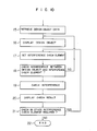
- the processing unit 5a receives the code of the design object area and fetches the process (computer program shown in Figs. 9 and 10) stored in the process memory 5b and sequentially carried out processing in accordance with the procedure.
- the first step fetched is a step shown in Fig. 9. After this step, the design object is entered so that a step of Fig. 10 is fetched and executed.
- a step 9 is first executed.
- Fig. II shows a detail of the step 9.
- a code of a design object area for example, a building floor code entered by the processing unit 5a is sent to the design attachment data memory 6 through the retrieval code output unit 5e, and a coordinate data of a corresponding design attachment is retrieved from the design attachment data memory 6 and stored in the intermediate data memory 5k through the data input unit 5f.
- the design attachment is an equipment
- an equipment pattern number is further sent to the standard equipment pattern data memory 8 through the retrieval code output unit 5i and a corresponding equipment pattern data is stored in the intermediate data memory 5k.
- the coordinate data of the design attachment retrieved and stored in the intermediate data memory 5k in the step 9A is supplied to the image data memory 3 through the image data output unit 5d (step 9B).
- the coordinate data of the menu items related to the input design object area are retrieved from the design object data memory 7 and stored in the intermediate data memory 5k through the data input unit 5h (step 9C).
- the coordinate data corresponding to the menu items shown in Fig. 5 are stored in the intermediate data memory 5k.
- step 9D the building floor code which indicates the area in which the input design object is to be located is sent to the design object data memory 7 through the retrieval code output unit 5g, and the system name data of the design object having that code is supplied to the processing unit 5a through the data input unit 5h.
- the system name data entered in the step 9D is stored in the intermediate data memory unit 5k (step 9E).
- the system name data shown in Fig. 4 is stored in the intermediate data memory 5k in the step 9E.
- step 9F system names "LPCS”, “HPCS”, “HD”, “RHR”, “RCW”, “RD”, “SPS”, “RCIC”, “RHRC”, “MS”, “FW”, “CUW” and “HV” corresponding to the menu items on page I, that is, menus I to 13 are fetched from the data in the list form which is shown in Fig. 4 and which is stored in the intermediate data memory 5k, and they are supplied to the image data memory 3 together with the coordinate data of the menu items shown in Fig. 5.
- the items "UPDATE” and “RETURN” are indicated by characters and they are supplied to the image data memory 3.
- Fig. 12 shows an example of the image displayed on the display device I after the step 9.
- the screen 25 of the display device I is divided into a design attachment display area 26, a design object connectivity chart display area 27 and a menu display area 28, and a design attachment image 26A, a connectivity image 27A and a menu item image 28A are displayed in the respective areas.
- Two display devices I may be used so that the image in the display area 26 is displayed on one of the display devices I and the images in the display areas 27 and 28 are displayed on the other display device I.
- An origin point - (Xmin, Ymin) of the image 28A is defined in the step 9 at a point displaced from an origin point of the screen 25 by Xa and Ya.
- the coordinate displayed on the screen 25 of the display device I is entered by the input device 4, and the design object name corresponding to the coordinate is selected from the design object data memory 7.
- Fig. 13 shows steps IOA -IOE of the step 10.
- a step IOB if it is determined in a step IOA that there is no system name to be laid out in the image 28A displayed in the menu item display area 28, the subsequent step is not carried out and the operation is terminated. If it is determined that there is a system name to be laid out, the steps IOB -IOE are carried out.
- designation In the steps IOB -10E, designation must be done by the input device 4. Accordingly, until an interrupt signal is supplied to the processor 5 from the input device 4 through the input unit 5c, a designation point is displayed on the screen 25 of the display device I corresponding to a designation coordinate.
- Fig. 14 shows steps 10F -101 of the step 10. If "UPDATE” or “RETURN” is not selected, the decisions in the steps 10F and 101 are "NO” and the process goes to steps 10J and 10K shown in Fig. 15. When “UPDATE” or “RETURN” in the menu display area 28 of the screen of Fig. 12 is selected, step 10H or 101 is carried out.
- steps IOA -IOH are specifically explained.
- Fig. 12 the designation by the input device 4 on the screen 25 of the display device I and the change of display are explained.
- pointing means (cursor) displayed on the image 28A of the menu display area 28 is aligned to the menu item "LPCS" by the input device 4.
- a coordinate (x, y) of the pointing means on the screen 25 is read into the processing unit 5a through the input unit 5c (step 10B) and written into the intermediate data memory unit 5k (step IOC).
- step IOC the intermediate data memory unit 5k
- the coordinate (x, y) is further written into the image data memory 3 through the image data output unit 5d (step IOD).
- step IOE When an interrupt signal is sent from the input device 4 to the processor 5 - (step IOE), the steps I0J and I0K are carried out if the decisions in the steps 10F and IOG are "NO" and the system name "LPCS" is supplied to and stored in the intermediate data memory unit 5k.
- Fig. 12 if there is no system name to be selected by an operator in the system names corresponding to the menues I to 13, "UPDATE" is selected in a step 10F and the image 28A in the menu display area 28 is re-displayed page by page as shown in Fig. 4.
- the updating of page may be done in the following manner.
- the pointing means (cursor) displayed in the menu display area is aligned to the menu item "UPDATE" by the input device 4 and an interrupt signal is sent from the input device 4 to the processor 5 so that the page number for the system name corresponding to the menu item shown in Fig. 12 is incremented by one.
- "UPDATE" in the menu display area 28 on the screen shown in Fig. 12 is designated by the input device 4
- a step 10H is carried out and the image 28A in the menu display area 28 changes to that shown on page 2 of Fig. 4.
- a step I0J based on the coordinate of the menu item of the image 28A on the display device I inputted in the step IOB and stored in the intermediate data memory 5k, the menu item corresponding to the above coordinate and the coordinate data of the menu item (Xmax, Ymax, Xmin and Ymin, see Fig. 5) are selected from the design object data memory 7 and they are stored in the intermediate data memory unit 5k through the data input unit 5h.
- a system name whose coordinate (x, y) of the menu item on the image 28A stored in the intermediate data memory unit 5k in the step I0C meets formulas (1) and (2) for the coordinate data of the menu item stored in the intermediate data memory unit 5k in the step I0J is selected from the intermediate data memory unit 5k.
- Fig. 16 shows a detail of the step II. Steps IIA and IIB shown in Fig. 16 are identical to the steps IIA and IIB described above.
- the menu item (system name) stored in the intermediate data memory unit 5k in the step 10 is sent to the design object data memory 7 through the data retrieval code output unit 5g, and a name (sub-system name) of the design object which has that menu item (system name) and which is not a branch line (branch system) is retrieved from the design object data memory 7 and supplies the retrieved design object name.
- the all sub-system names entered in the step IIB is stored in the intermediate data memory unit 5k (step IIC).
- a step IID the menu items stored in the intermediate data memory unit 5k in the step IIC are displayed in the corresponding areas on the screen 25, in the same manner as that in the step 9F.
- An example of the image displayed in the menu display area 28 of the display device I is shown in Fig. 17.
- the image 28B displayed in the menu display area 28 indicates all sub-system items concerning the menu item "LPCS".
- the step 12 of the present embodiment comprises the steps IOA -IOK like the step 10 described above.
- the "System Name" in the step IOA of the step 10 is changed to "Sub-System Name".
- the image at the end of the step 9 is displayed (Fig. 12).
- the menu item "RETURN" is designated when the page I of the menu content is displayed on the menu display area 28, the image at the end of the step 9 (Fig. 12) is displayed on the screen 25.
- Fig. 18 shows a detail of the step 13.
- the sub-system name temporarily stored in the intermediate data memory unit 5k in the step 12 is sent to the design object data memory 7 through the retrieval code output 5g, and a data representing the connectivity with the corresponding sub-system is retrieved from the specification data of the sub-systems stored in the design object data memory 7 and temporarily stored in the intermediate data memory unit 5k.
- the data representing the sub-system connectivity shown in Fig. 7 is stored in the intermediate data memory unit 5k.
- step 13C display position coordinates of the components of the sub-system stored in the intermediate data memory unit 5k and display position coordinates of the names of the components are determined in order to display the shapes of the components of the sub-system in the design object connectivity chart display area 27 on the display device I based on the connectivity of the sub-system stored in the intermediate data memory unit 5k, and those coordinates are written into the intermediate data memory unit 5k.
- Fig. 19 shows a detailed process flow of the step 13C.
- steps 13C, and 13C 2 coordinates of a start point and an end point of the sub-system and a Y coordinate of an end point element of a branch line for displaying the components in the design object connectivity chart display area 27 are retrieved from the design object data memory 7 based on the corresponding sub-system, and they are read into the processing unit 5a through the data input unit 5h. Then, those coordinate data are stored in the intermediate data memory unit 5k. Thus, the coordinate data shown in Fig. 6 is stored in the design object data memory 7.
- a step 13C 3 the distance between the start point and the end point is equi-divided based on the coordinates to be used as start points and end points of the components of the sub-system stored in the intermediate data memory unit 5k and the number of components excluding the start points and the end points retrievable from the data in the list form shown in Fig. 7, and the display position coordinates of the components are allocated in the order of the components.
- the display position for the end point of the branch line is determined by the given Y coordinate and the X coordinate determined in the manner described above.
- the sub-system "600A-LPCS-3", as seen from Figs. 6 and 7,
- a step 13C character display position coordinates for displaying names of the components are determined based on the display position coordinates of.the components.
- step 13C 5 the display position coordinates for displaying the components representing the connectivity of the sub-system and the display position coordinates for displaying the names of the components are written into the intermediate data memory unit 5k.
- Fig. 20 shows the display position coordinates of the components and the names stored in the intermediate data memory unit 5k in the step 13C s .
- a step 13D shape data of the components of the sub-system (for example, 600A-LPCS-3) are stored in the intermediate data memory unit 5k.
- the step 13D comprises steps 13D, -130. as shown in Fig. 21.
- the names of the components (excluding the branch) stored in the intermediate data memory unit 5k and shown in Fig. 20 are sent to the design object data memory 7 through the retrieval code output unit 5g, and the standard pattern numbers of the components are read from the sub-system specification data through the input unit 5h.
- the standard pattern numbers are written into the intermediate data memory unit 5k.
- a step 13D the standard pattern numbers stored in the intermediate data memory unit 5k are sent to the standard equipment pattern data memory 8 through the retrieval code output unit 5i to retrieve the equipments having the corresponding standard pattern numbers and the shape data of the standard equipment patterns related to the equipments are read into the processor 5 through the data input unit 5j.
- the shape data are stored in the intermediate data memory unit 5k.
- the shape data shown in Fig. 8 is stored in the intermediate data memory unit 5k in the step 13D..
- the display position coordinates of the components representing the connectivity of the sub-system "600A-LPCS-3" and the names thereof stored in the intermediate data memory unit 5k, and the shape data of the components are related to each other, and supplied to the image data memory 3 through the image data memory unit 5d.
- the coordinate data stored in the image data memory unit 5d in the above step is read into the image display controller 2 and displayed in the design object connectivity chart display area 27 of the display device I as the image 27A (Fig. 22).
- steps 13E -13H the sub-system name temporarily stored in the intermediate data memory 5k in the step 12 is sent to the design object data memory 7 through the retrieval code output unit 5g to retrieve the specification data of the corresponding sub-system, a name of a first branch line (branch system) which directly branches from the sub-system is stored into the intermediate data memory unit 5k through the data input unit 5h.
- the steps 13E -13H are identical to the steps IIA -IID.
- the name of the first branch line stored in the intermediate data memory unit 5k in the step 13H is supplied to the image data memory 3 and displayed as a menu item in the menu display area 28 of the display device I.
- the image 28C in the menu display area 28 is displayed in Fig. 22.
- the image shown in Fig. 22 is displayed on the display device (by the image display controller 2 by supplying to the image data memory 3 the data stored in the intermediate data memory 5k through the steps 13A -13H.
- a step 131 the name of the sub-system stored in the intermediate data memory unit 5k is sent to the design object data memory 7 through the retrieval code output unit 5g, and the specification data of the sub-system is retrieved and the coordinates of the start point and the end point are read into through the data input unit 5h, and they are written into the intermediate data memory unit 5k together with index shape data for displaying the start point and the end point on the display screen.
- the start point and end point data and the index shape data stored in the intermediate data memory unit 5k are supplied to the image data memory 3.
- Indices (arrows) 71 and 72 are displayed at the coordinates of the start point and the end point of the sub-system "600A-LPCS-3" (Fig. 22).
- Fig. 23 shows a detail of the step 14.
- curve points of indices 71 and 72 displayed on the screen 25 are designated by the input device 4 for the layout.
- the coordinates of the curve points are stored in the intermediate data memory 5k as layout information (step 14B).
- steps 14C -14E in order to determine locations of the components, that is, the components of the sub-system "600A-LPCS-3", the components of the sub-system in the image 27A displayed in the design object connectivity chart display area 27 are designated (step 14C), and a point on a route (displayed on the screen 25 after the step 15B) of the sub-system displayed in the design attachment display area 26 is designated (step 14D), and the display position coordinate and the shape data are written into the intermediate data memory unit 5k as component position information.
- the data stored in the intermediate data memory unit 5k in the steps 14A -14E are supplied to the image data memory 3 and displayed on the display device I.
- Fig. 24 shows the image displayed on the display device I. In Fig.
- numeral 73 denotes a branch point of "IOOA-LPCS-37" and numeral 74 denotes a branch point of "65A-LPCS-45”. If the item "RETURN" in the menu display area 28 on the screen 25 is designated, the following step is terminated and the status prior to the step 12 is assumed and the image shown in Fig. 17 is displayed on the display device I.
- a step '14F is carried out.
- the layout information of the sub-system (for example, 600A-LPCS'3) stored in the intermediate data memory 5k is written into the specification data of the design object of the design object data memory 7. Accordingly, the registered layout of the design object is displayed in the design object display area 26, and the branch lines "IOOA-LPCS-37" and "65A-LPCS-45” are laid out in the image 26A in the same manner as that for the sub-system.
- step 12 and the subsequent steps are completed for all sub-systems (all sub-systems displayed in the menu display area 28 of Fig. 17) of one system (for example, LPCS), the step 10 and the subsequent steps are carried out for other system (than LPCS) displayed in the menu display area 28 in Fig. 12.
- the decision in the step IOA is "NO" and the layout in one design object area is completed.
- the layout in the other design object area is necessary, the process is restarted from the step 9.
- the design object can be easily arranged in the design object area. Since the connection of the design attachment and the components of the design object is displayed as the image, the arrangement of the design object can be very efficiently done.
- a design drawing is displayed on the screen 25 of the display device I to show it to the operator, and a chart showing connection of the design object is also displayed on the screen of the display device. Accordingly, the components can be arranged without error. Since the connection from the upstream to the down stream such as system, sub-system, first branch line and second branch line is orderly and systematically defined even if a layout of a design object having a complex connection (branch) is to be designed, the layout may be designed starting from the upstream - (main flow) or main section and a chart representing the connection of the downstream (branch flow) or minor section may be sequentially prepared. Accordingly, mismatching of connection specification by the operator is prevented and the layout work is efficiently carried out.
- the operator can easily check the design object lay out in the design object area while he/she watches the connection image.
- steps 15A and 15B shown in Fig. 25 are carried out.
- the code of the design object is entered by the operator through the input device 4 (step 15A).
- the processing unit 5a retrieves the layout information of the design object (stored in the step 14F) by the design object data memory 7 and the display data (data of the image 26A of Fig. 12) of the design attachment in the design object area in which the design object is arranged, by the design object data memory 6, and stores the retrieved data into the intermediate data memory unit 5k (step 15B).
- a step 16 following to the step 15 comprises steps 16A -16C shown in Fig. 26.
- a display condition view point, reference point, magnification, etc.
- Fig. 27 shows the display condition read in the step 16A.
- the display data of the design attachment stored in the intermediate data memory unit 5k and the layout data of the design object are translated to three-dimension coordinate data in accordance with the input display condition and the translated data are stored in the intermediate data memory unit 5k.
- the coordinates (X, Y, Z) of the layout data of the design object and the display data of the design attachment are translated to the coordinates (X', Y', X') of the three-dimension coordinate data in accordance with the following formula.
- a 11 -a 13 , a 21 -a 23 and a 31 -an are terms relating to rotation, expansion and reduction, and a14, a.4, a34 are terms relating to parallel shift.
- the translated three-dimension coordinate data (X', Y', Z') of the design object are written into the image data memory 3 through the image data output unit 5d (step 16C).
- the image display controller 2 fetches the coordinate data (X', Y', Z') from the image data memory 3 as the image data and displays it on the display device I.
- Numeral 32 denotes a pipe for a line 002 of a system "LPCS”
- numeral 33 denotes a pump
- numeral 34 denotes a value
- numeral 31 denotes a footway.
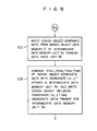
- a step 17 an interference check element is selected and an absolute coordinate (X', Y', Z') of a shape of the interference check element is determined.
- Fig. 29 shows a detail of the step 17.
- the operator enters a type of the interference check element and data of size of the interference check element (Xmax, Xmin, Ymax, Ymin, Zmax, Zmin) through the input device 4 (step 17A).
- the type of the interference check element includes imitation of human being, equipment and pipe to be transported in or out, transport apparatus, equipment to be disassembled and checked, manufacturing apparatus, and check device.
- the manufacturing apparatus may be an automatic welding apparatus used for installation or repair work
- the check device may be an ultrasonic fault locating device or a moving check device.
- a step 17A the imitation of human being is entered as the interference check element.
- the operator enters the position data (X, Y, Z) of the interference check element through the input device 4 (step 17B).
- the position of the interference check element is designated by the operator while he/she watches the image of Fig. 28.
- the arrangement of the imitation of human being as the interference check element in a path 31 of Fig. 28 designates a coordinate of the path 31.
- a standard pattern shape data of the corresponding interference check element is selected from the standard pattern shape data memory 8 in accordance with the type of the interference check element and the selected data is supplied to the intermediate data memory unit 5k.
- the selected standard pattern shape data is corrected based on the data of the size of the interference check element so that it has the size designated by the operator (step 17D). Then, in a step 17E, the absolute coordinate (X', Y', Z') of the shape data of the interference check element is determined and supplied to the image data memory 3 from the intermediate data memory unit 5k and the image data output unit 5d.
- the imitation of human being as the interference check element is displayed in the path 31 on the screen of the display device I as if there were an actual human being (Fig. 30). In Fig. 30, numeral 35 denotes the imitation of human being.
- the absolute coordinate (X'max, X'min, Y'max, Y'min, Z'max, Z'min) of the interference check range is determined based on the size data and position data of the interference check element and it is supplied to the intermediate data memory unit 5k.
- the absolute coordinate of the interference check range is determined by the following formulas.
- a step 18 whether the check of interference between the design object and the interference check element is necessary or not is designated.
- the operator designates the requirement or non-requirement of the interference check through the input device 4.
- a step 18A of Fig. 31 an interference check flag supplied from the input device 4 is supplied to the processing unit 5a through the input unit 5c.
- the processing unit 5a determines whether the input flag indicates the necessity of the interference check or not (step 18B). If the interference check is not necessary in the step 18B, the process returns to the step 16 and other design object entered in the step 15A is displayed and the subsequent steps are carried out. If the interference check is necessary in the step 18B, a step 19 is carried out.
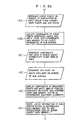
- Fig. 32 shows a detail of the step 19.
- a step 19A the absolute coordinate of the interference check range determined in the step 17E is fetched from the intermediate data memory unit 5k into the processing unit 5a.
- a data counter which is related under a certain condition with the design object data number of the components of the design object and the pipes which are to be checked for the interference with the interference check element designated by the input signal in the step 17A, is initialized by the processing unit 5a.
- the design object data number and the data counter may have one-to-one correspondence. When the design object data number and the data counter have one-to-one correspondence, the design object data counter can be set to "I" in the step 19B.
- a step 19C the design object data designated by the data counter (design object data of the area including the components and pipes for which interference with the interference check element is to be checked) and the design object data of the area in which the components designated by the design object data are arranged are fetched from the intermediate data memory unit 5k and supplied to the processing unit 5a.
- the fetched design object data and design attachment data have been translated to the three-dimensional bsolute coordinate data in the step 16C.
- a step 19D the absolute coordinates of the design object data and the design attachment data fetched in the step 19C and the shape data of the interference check element fetched from the intermediate data memory unit 5k (which are stored in the intermediate data memory unit 5k in the step 17E) are supplied to the image data memory 3 through the image data output unit 5d.
- Those design object data, design attachment data and shape data are displayed on the display device I.
- the displayed image is shown in Fig. 30.
- Numeral 35 denotes the imitation of human being.
- a step 19E whether the absolute coordinate (X', Y', Z') of the design object data fetched in the step 19C or line segments connecting certain absolute coordinates (line segments outlining the surface of the design object) interfere with the interference check range or not is checked.
- the check is done in the following manner.
- the design object data is included in the interference check range, that is, the corresponding design object interferes with the interference check element when the following conditions are met.
- the line segments connecting certain design object data when an absolute coordinate (X,' Y,', Z,') of one end point of the line segment satisfies the three conditions of the item (a) described below, or when the line segment has a crosspoint with any one of planes I -6 shown in the item (b), the line segment is included in the interference check range, that is, the corresponding design object interferes with the interference check element.
- step 19F If it is determined in the step 19E that a portion or all of the components (or pipes) of the design object fetched in the step 19C are not included in the interference check range, a step 19F is carried out.
- the count of the data counter is updated to the next count.
- the process returns to the step 19C and the design object data corresponding to the count of the updated data counter and the design attachment data corresponding to the design object data are fetched from the intermediate data memory unit 5k.
- step 19D the design object and the design object data are supplied to the image data memory 3 and the components based on the design object and design attachment data are displayed on the display device I.
- the X-Y or two-axis coordinate of the image of the components shifts from that of the image displayed before the data counter is updated.
- the image of the components displayed on the display device I based on the design object outputted in the step 19D after the updating of the data counter appears moving.
- the backside of the path 31 moves forward.
- the coordinate of the arrangement position of the interference check element is also changed in the step 19D. The change is in the opposite direction to the change of the coordinates of the components of the design object and absolute values of changes are equal.
- the shape data of the interference check element and the absolute coordinate of the interference check range are determined in manners similar to the steps 17E and 17F.
- the absolute coordinate of the new shape data is supplied to the image data memory 3 in the step 19D and displayed on the display device I. Since the absolute values of the changes are equal as described above, the interference check element is displayed on the screen of the display device I at the same point as that prior to the updating of the data counter. However, since the image of the components moves as described above, it appears as if the interference check element (the imitation 35 of human being in the present embodiment) advances along the path 31.
- the interference check element the imitation 35 of human being in the present embodiment
- step 19F and the steps 19C -19E after the updating are again carried out.
- step 19E if the interference between the components of the design object and the interference check range is detected, a step 19G is carried out.
- the step 19G the area of the components of the design object which interfere with the interference check range is determined and the data of the interference area is stored in the intermediate data memory unit 5k, and the count of the data counter which has caused the interference is stored in the intermediate data memory unit 5k.
- the step 19 is terminated.
- the steps 19F, 19C, 19D and 19E may be repeatedly carried out.
- a step 20 is carried out.
- the interference check result is displayed as shown in Fig. 33.
- the data of the interference area stored in the intermediate data memory unit 5k is fetched and red display data is added to the interference area data and it is supplied to the image data memory 3 through the image data output unit 5d.
- the interference area is displayed in red on the screen of the display device I.
- An area 36 in Fig. 30 is displayed in red indicating the interference.
- the count of the counter stored in the intermediate data memory unit 5k in the step 19G is fetched, and based on the fetched count, the type of the design object, the system name of the design object and the data number are retrieved (step 20C).
- a display character string is prepared and supplied to the image data memory 3 through the image data output unit 5d (step 20D).
- the character string is displayed on the display device I as the image 37 (Fig. 30).
- the operator determines whether the interference check by other check element is required or not and it is entered by the input device 4. This signal is supplied to the processing unit 5a and a step 21 is carried out. If the processing unit 5a determines that the check by the other interference check element is required, the steps 17 -20 are carried out for the new interference check element. The step 21 may be automatically carried out without designation by the operator. In this case, a procedure for detecting the interference check elements for which the interference check has been completed and the interference check elements which require the interference check and carrying out the interference check sequentially to the remaining interference check element may be incorporated and the process is carried out in accordance with the procedure. If the check by other interference check element is not required, the process ends (step 22). If the interference check is to be carried out to a new design object (for example, another system), the process is carried out again from the step 15.
- a new design object for example, another system
- Figs. 34 to 36 show images of the interference check results displayed on the display device I.
- Fig. 34 shows an image displayed when a pump 38 is transported in by a whist 39. Since there is no interference between the moving pump 38 which is the interference check element and the components of the design object, "NO INTERFERENCE" is displayed on the display device I.
- a pipe 41 is fault-located by an ultrasonic fault location device (interference check element) 40. Again, “NO INTERFERENCE” is displayed because there is no interference.
- the ultrasonic fault location can be carried out without interference with other pipes and equipments even if the ultrasonic fault location device 40 mounted on the pipe 41 is moved around the pipe 41 for checking.
- Fig. 36 shows an image displayed when a valve 42 (interference check element) to be checked is hung by the whist 43 and removed from the pipe.
- Numeral 42A denotes a portion to which the valve 42 is to be attached.
- the portion 42A is displayed in white to indicate a detached status. Again, "NO INTERFERENCE” is displayed and it can be previously confirmed that a sufficient space for moving the removed valve 42 is assured.
- any obstacle which a man may encounter when he walks along the path in the design object area (or walks up or down a step) can be previously checked, and if there is an obstacle, a design correction can be made to eliminate the obstacle. Such correction may also be applied when "INTERFERENCE" is detected in Figs. 34 -36.
- the interference between the interference check element which imitates the article or human being moving in the design object area and the components of the design object can be readily checked in the design stage by the simulation in the steps 15 -20 while the components of the design object are arranged. Since the interference can be checked by the simulation while the interference check element and the design object are displayed on the display device I such that the interference check element relatively moves, the interference with the moving article (or human being) in a state in which the design object is actually installed can be previously and efficiently checked.
- the interference check element corresponds to the article or human being moving in a predetermined space in the design object area in which the design object is arranged. If there is an interference, the interference area is displayed so that the interference area can be readily detected. Rearrangement of the components of the design object to eliminate the interference area can also be readily made. Accordingly, a moving space of the movable article after the installation of the design object can be readily set in the design state.'
- the data counter used in the step 19B is a procedure having a counter function, and the procedure is stored in the process memory unit 5b.
- the procedure of the data counter is fetched when the step 19B is carried out.
- the interference between the movable article which moves in the area in which the component of the design object are arranged and the components of the design object is checked by the simultation so that any interference can be readily detected in the design stage.
Landscapes
- Engineering & Computer Science (AREA)
- Physics & Mathematics (AREA)
- Geometry (AREA)
- Theoretical Computer Science (AREA)
- General Physics & Mathematics (AREA)
- Computer Hardware Design (AREA)
- General Engineering & Computer Science (AREA)
- Structural Engineering (AREA)
- Computational Mathematics (AREA)
- Civil Engineering (AREA)
- Mathematical Analysis (AREA)
- Mathematical Optimization (AREA)
- Pure & Applied Mathematics (AREA)
- Evolutionary Computation (AREA)
- Architecture (AREA)
- Processing Or Creating Images (AREA)
Applications Claiming Priority (2)
| Application Number | Priority Date | Filing Date | Title |
|---|---|---|---|
| JP60253767A JPH0738198B2 (ja) | 1985-11-14 | 1985-11-14 | 設計支援方法及びその装置 |
| JP253767/85 | 1985-11-14 |
Publications (3)
| Publication Number | Publication Date |
|---|---|
| EP0222387A2 true EP0222387A2 (de) | 1987-05-20 |
| EP0222387A3 EP0222387A3 (en) | 1988-12-14 |
| EP0222387B1 EP0222387B1 (de) | 1994-08-31 |
Family
ID=17255856
Family Applications (1)
| Application Number | Title | Priority Date | Filing Date |
|---|---|---|---|
| EP86115709A Expired - Lifetime EP0222387B1 (de) | 1985-11-14 | 1986-11-12 | Verfahren zur Erzeugung einer Entwurfreferenz und Gerät dafür |
Country Status (5)
| Country | Link |
|---|---|
| US (1) | US5006991A (de) |
| EP (1) | EP0222387B1 (de) |
| JP (1) | JPH0738198B2 (de) |
| KR (1) | KR930003127B1 (de) |
| DE (1) | DE3650052T2 (de) |
Cited By (4)
| Publication number | Priority date | Publication date | Assignee | Title |
|---|---|---|---|---|
| EP0539179A3 (en) * | 1991-10-24 | 1993-10-06 | Canon Kabushiki Kaisha | Kinematic-simulation apparatus and kinematic-simulation method |
| EP0621545A3 (de) * | 1993-04-21 | 1995-12-13 | Hitachi Ltd | Rechnergestütztes Entwurfs- und Anfertigungssystem für Bauteilanordnung und Rohrverlegungsplanung. |
| KR100246066B1 (ko) * | 1995-03-24 | 2000-03-15 | 포만 제프리 엘 | 컴퓨터 그래픽 시스템 및 그래픽 시스템 동작 제어 방법 |
| KR100246520B1 (ko) * | 1995-04-27 | 2000-03-15 | 가시오 가즈오 | 화상처리장치 |
Families Citing this family (33)
| Publication number | Priority date | Publication date | Assignee | Title |
|---|---|---|---|---|
| JP2668034B2 (ja) * | 1989-02-06 | 1997-10-27 | 株式会社日立製作所 | 建設装置 |
| JP2947830B2 (ja) * | 1989-09-11 | 1999-09-13 | 株式会社日立製作所 | 放射線作業支援方法及びその支援装置 |
| US5430837A (en) * | 1990-03-27 | 1995-07-04 | Mitsubishi Denki Kabushiki Kaisha | Mechanism conceptual drawing formation method and apparatus |
| US5557537A (en) * | 1990-07-12 | 1996-09-17 | Normann; Linda M. | Method and apparatus for designing and editing a distribution system for a building |
| JPH0498466A (ja) * | 1990-08-10 | 1992-03-31 | Fujitsu Ltd | 要素配置装置 |
| JP2865828B2 (ja) * | 1990-08-22 | 1999-03-08 | 株式会社日立製作所 | 操作手順の表示方法及びその装置 |
| JPH0789382B2 (ja) * | 1991-03-14 | 1995-09-27 | インターナショナル・ビジネス・マシーンズ・コーポレイション | 形状モデルを生成する方法及び装置 |
| US5225987A (en) * | 1991-05-20 | 1993-07-06 | Westinghouse Electric Corp. | System for implementing a PC computer configuration system for assembling and mounting of a complex product in situ |
| JP2957308B2 (ja) * | 1991-06-04 | 1999-10-04 | 日本精工株式会社 | 自動作画発注装置及び自動作画発注方法 |
| JP3225635B2 (ja) * | 1992-10-20 | 2001-11-05 | 株式会社日立製作所 | 建設支援装置及び方法 |
| US5343385A (en) * | 1993-08-17 | 1994-08-30 | International Business Machines Corporation | Interference-free insertion of a solid body into a cavity |
| US5625827A (en) * | 1993-09-21 | 1997-04-29 | Gary M. Krause | Method and system of blueprint document manipulation |
| JP3214776B2 (ja) * | 1994-04-13 | 2001-10-02 | 株式会社東芝 | 仮想環境表示装置および方法 |
| US5815154A (en) * | 1995-12-20 | 1998-09-29 | Solidworks Corporation | Graphical browser system for displaying and manipulating a computer model |
| US6219055B1 (en) * | 1995-12-20 | 2001-04-17 | Solidworks Corporation | Computer based forming tool |
| US5844566A (en) * | 1996-02-12 | 1998-12-01 | Dassault Systemes | Method and apparatus for controlling shadow geometry on computer displays |
| US6056428A (en) * | 1996-11-12 | 2000-05-02 | Invention Machine Corporation | Computer based system for imaging and analyzing an engineering object system and indicating values of specific design changes |
| US5950206A (en) * | 1997-04-23 | 1999-09-07 | Krause; Gary Matthew | Method and apparatus for searching and tracking construction projects in a document information database |
| US5901068A (en) * | 1997-10-07 | 1999-05-04 | Invention Machine Corporation | Computer based system for displaying in full motion linked concept components for producing selected technical results |
| US6289496B1 (en) * | 1998-06-29 | 2001-09-11 | Xilinx, Inc. | Placement of input-output design objects into a programmable gate array supporting multiple voltage standards |
| US6625795B1 (en) | 1998-06-29 | 2003-09-23 | Xilinx, Inc. | Method and apparatus for placement of input-output design objects into a programmable gate array |
| US6611725B1 (en) * | 2000-02-03 | 2003-08-26 | Solidworks Corporation | Computer drawing system |
| JP2003044530A (ja) * | 2001-07-30 | 2003-02-14 | Toshiba Corp | 構造物形状定義装置、構造物形状定義方法、並びに構造物形状定義用プログラム、及び設計図面作成装置 |
| US7010759B2 (en) * | 2002-04-05 | 2006-03-07 | U-Tech Enviromental Manufacturing Supply, Inc. | Method for real time display of maintenance device location in an internal space |
| US7286975B2 (en) * | 2002-10-24 | 2007-10-23 | Visteon Global Technologies, Inc. | Method for developing embedded code for system simulations and for use in a HMI |
| US7426578B2 (en) * | 2003-12-12 | 2008-09-16 | Intercall, Inc. | Systems and methods for synchronizing data between communication devices in a networked environment |
| WO2007088630A1 (ja) * | 2006-02-03 | 2007-08-09 | Fujitsu Limited | 検証装置、検証方法及び検証プログラム |
| US7518606B2 (en) * | 2006-04-04 | 2009-04-14 | Autodesk, Inc. | System and method for generating curved pipe objects for computer aided design models |
| US7644363B2 (en) * | 2006-04-10 | 2010-01-05 | Autodesk, Inc. | “For-each” label components in CAD drawings |
| JP2008027045A (ja) * | 2006-07-19 | 2008-02-07 | Fanuc Ltd | 干渉チェック機能を備える数値制御装置 |
| US8718982B2 (en) * | 2008-09-18 | 2014-05-06 | 3Shape A/S | Tools for customized design of dental restorations |
| US10824680B2 (en) * | 2012-10-02 | 2020-11-03 | The Boeing Company | Panoptic visualization document access control |
| WO2014142929A1 (en) * | 2013-03-14 | 2014-09-18 | Trifecta Global Infrastructure Solutions, Ltd. | Systems and methods for advanced sanitary sewer infrastructure management |
Family Cites Families (5)
| Publication number | Priority date | Publication date | Assignee | Title |
|---|---|---|---|---|
| US3867616A (en) * | 1968-09-03 | 1975-02-18 | Badger Co | Automated designing |
| GB1443019A (en) * | 1973-12-07 | 1976-07-21 | Qeleq Ltd | Computer systems |
| JPS5597245A (en) * | 1979-01-19 | 1980-07-24 | Mitsubishi Heavy Ind Ltd | Apparatus for processing and assembling piping member for plant |
| DE3109784A1 (de) * | 1981-03-13 | 1982-10-14 | Siemens AG, 1000 Berlin und 8000 München | Einrichtung zum betrieb eines greiferkrans einer verladebruecke zum be- oder entladen eines schiffes |
| US4512747A (en) * | 1982-01-13 | 1985-04-23 | Hitchens Max W | Material conveying system simulation and monitoring apparatus |
-
1985
- 1985-11-14 JP JP60253767A patent/JPH0738198B2/ja not_active Expired - Lifetime
-
1986
- 1986-11-12 DE DE3650052T patent/DE3650052T2/de not_active Expired - Fee Related
- 1986-11-12 EP EP86115709A patent/EP0222387B1/de not_active Expired - Lifetime
- 1986-11-13 KR KR1019860009596A patent/KR930003127B1/ko not_active Expired - Fee Related
-
1990
- 1990-01-09 US US07/463,005 patent/US5006991A/en not_active Expired - Fee Related
Non-Patent Citations (3)
| Title |
|---|
| BROWN BOVERI REVIEW, vol. 71, no. 3/4, March/April 1984, pages 154-159, Baden, CH; W. D\MER et al.: "Computer-aided plant design with RAPAS" * |
| COMPUTERS & GRAPHICS, vol. 7, no. 3/4, 1983, pages 285-293, Pergamon Press Ltd, Exeter, GB; T. UCHIKI et al.: "Collision detection in motion simulation" * |
| COMPUTERS & GRAPHICS, vol. 9, no. 4, 1985, pages 449-453, Pergamon Press Ltd, New York, US; P.P. COMNINOS: "Computer animation in interior and industrial design" * |
Cited By (6)
| Publication number | Priority date | Publication date | Assignee | Title |
|---|---|---|---|---|
| EP0539179A3 (en) * | 1991-10-24 | 1993-10-06 | Canon Kabushiki Kaisha | Kinematic-simulation apparatus and kinematic-simulation method |
| US5945994A (en) * | 1991-10-24 | 1999-08-31 | Canon Kabushiki Kaisha | Kinematic-simulation apparatus and kinematic-simulation method with interference processing |
| EP0621545A3 (de) * | 1993-04-21 | 1995-12-13 | Hitachi Ltd | Rechnergestütztes Entwurfs- und Anfertigungssystem für Bauteilanordnung und Rohrverlegungsplanung. |
| US5740341A (en) * | 1993-04-21 | 1998-04-14 | Hitachi, Ltd. | Design and production supporting system for component arrangement and pipe routing |
| KR100246066B1 (ko) * | 1995-03-24 | 2000-03-15 | 포만 제프리 엘 | 컴퓨터 그래픽 시스템 및 그래픽 시스템 동작 제어 방법 |
| KR100246520B1 (ko) * | 1995-04-27 | 2000-03-15 | 가시오 가즈오 | 화상처리장치 |
Also Published As
| Publication number | Publication date |
|---|---|
| JPH0738198B2 (ja) | 1995-04-26 |
| KR930003127B1 (ko) | 1993-04-19 |
| DE3650052D1 (de) | 1994-10-06 |
| DE3650052T2 (de) | 1995-03-16 |
| US5006991A (en) | 1991-04-09 |
| KR870005310A (ko) | 1987-06-08 |
| EP0222387A3 (en) | 1988-12-14 |
| JPS62114063A (ja) | 1987-05-25 |
| EP0222387B1 (de) | 1994-08-31 |
Similar Documents
| Publication | Publication Date | Title |
|---|---|---|
| EP0222387A2 (de) | Verfahren zur Erzeugung einer Entwurfreferenz und Gerät dafür | |
| EP0195976B1 (de) | Entwerfungsunterstützungsverfahren und Gerät dafür | |
| US4992953A (en) | Computer assisted design method and apparatus | |
| US5740341A (en) | Design and production supporting system for component arrangement and pipe routing | |
| US4829446A (en) | Method and apparatus for recording and rearranging representations of objects in a model of a group of objects located using a co-ordinate system | |
| JP4000198B2 (ja) | 会話型回路設計装置 | |
| US4831546A (en) | Method and apparatus for assisting layout design | |
| WO1999045504A1 (en) | Apparatus and method for manually selecting, displaying and repositioning dimensions | |
| CN108664722A (zh) | 基于增强现实的卫星电缆铺设导引系统及导引方法 | |
| US5265040A (en) | Method and device for displaying information on simulation result in a numerical simulation system | |
| CN116670675A (zh) | 快速定位图形系统和方法 | |
| JP2003011822A (ja) | 列車運行管理用情報生成装置、列車運行管理用情報生成プログラムおよび列車運行管理用情報生成方法 | |
| JPH0981608A (ja) | 筐体製造支援システム | |
| JP5260415B2 (ja) | プリント配線パターン表示装置及びそれを用いたシステム | |
| JPH06168246A (ja) | 据付け計画支援方法及びその装置 | |
| JPH06103499B2 (ja) | 設計支援装置 | |
| JP3108605B2 (ja) | 図形の属性表示方法 | |
| Ariansyah et al. | in Assisted Aircraft Cable Assembly | |
| JPS6319074A (ja) | レイアウト評価支援装置 | |
| JP2646828B2 (ja) | 配置修正方式 | |
| JP3312233B2 (ja) | 図面管理装置 | |
| JP2874289B2 (ja) | 基板cad装置 | |
| JP2914302B2 (ja) | 配線設計の配線制限表示方法 | |
| JP3247730B2 (ja) | 出図装置 | |
| JP3798946B2 (ja) | Cad図面のケーブル芯線数の整合性保持方法およびシステム |
Legal Events
| Date | Code | Title | Description |
|---|---|---|---|
| PUAI | Public reference made under article 153(3) epc to a published international application that has entered the european phase |
Free format text: ORIGINAL CODE: 0009012 |
|
| AK | Designated contracting states |
Kind code of ref document: A2 Designated state(s): DE FR GB SE |
|
| PUAL | Search report despatched |
Free format text: ORIGINAL CODE: 0009013 |
|
| AK | Designated contracting states |
Kind code of ref document: A3 Designated state(s): DE FR GB SE |
|
| 17P | Request for examination filed |
Effective date: 19881219 |
|
| 17Q | First examination report despatched |
Effective date: 19900313 |
|
| GRAA | (expected) grant |
Free format text: ORIGINAL CODE: 0009210 |
|
| AK | Designated contracting states |
Kind code of ref document: B1 Designated state(s): DE FR GB SE |
|
| REF | Corresponds to: |
Ref document number: 3650052 Country of ref document: DE Date of ref document: 19941006 |
|
| ET | Fr: translation filed | ||
| EAL | Se: european patent in force in sweden |
Ref document number: 86115709.7 |
|
| PLBE | No opposition filed within time limit |
Free format text: ORIGINAL CODE: 0009261 |
|
| STAA | Information on the status of an ep patent application or granted ep patent |
Free format text: STATUS: NO OPPOSITION FILED WITHIN TIME LIMIT |
|
| 26N | No opposition filed | ||
| PGFP | Annual fee paid to national office [announced via postgrant information from national office to epo] |
Ref country code: SE Payment date: 20011002 Year of fee payment: 16 |
|
| PGFP | Annual fee paid to national office [announced via postgrant information from national office to epo] |
Ref country code: FR Payment date: 20011022 Year of fee payment: 16 |
|
| PGFP | Annual fee paid to national office [announced via postgrant information from national office to epo] |
Ref country code: GB Payment date: 20011116 Year of fee payment: 16 |
|
| PGFP | Annual fee paid to national office [announced via postgrant information from national office to epo] |
Ref country code: DE Payment date: 20011230 Year of fee payment: 16 |
|
| REG | Reference to a national code |
Ref country code: GB Ref legal event code: IF02 |
|
| PG25 | Lapsed in a contracting state [announced via postgrant information from national office to epo] |
Ref country code: GB Free format text: LAPSE BECAUSE OF NON-PAYMENT OF DUE FEES Effective date: 20021112 |
|
| PG25 | Lapsed in a contracting state [announced via postgrant information from national office to epo] |
Ref country code: SE Free format text: LAPSE BECAUSE OF NON-PAYMENT OF DUE FEES Effective date: 20021113 |
|
| PG25 | Lapsed in a contracting state [announced via postgrant information from national office to epo] |
Ref country code: DE Free format text: LAPSE BECAUSE OF NON-PAYMENT OF DUE FEES Effective date: 20030603 |
|
| EUG | Se: european patent has lapsed | ||
| GBPC | Gb: european patent ceased through non-payment of renewal fee | ||
| PG25 | Lapsed in a contracting state [announced via postgrant information from national office to epo] |
Ref country code: FR Free format text: LAPSE BECAUSE OF NON-PAYMENT OF DUE FEES Effective date: 20030731 |
|
| REG | Reference to a national code |
Ref country code: FR Ref legal event code: ST |