EP0222549A2 - Outil susceptible de fonctionner continûment dans l'application dans un processus d'une ligne de production - Google Patents
Outil susceptible de fonctionner continûment dans l'application dans un processus d'une ligne de production Download PDFInfo
- Publication number
- EP0222549A2 EP0222549A2 EP86308371A EP86308371A EP0222549A2 EP 0222549 A2 EP0222549 A2 EP 0222549A2 EP 86308371 A EP86308371 A EP 86308371A EP 86308371 A EP86308371 A EP 86308371A EP 0222549 A2 EP0222549 A2 EP 0222549A2
- Authority
- EP
- European Patent Office
- Prior art keywords
- wire
- drum
- point
- tool
- pick
- Prior art date
- Legal status (The legal status is an assumption and is not a legal conclusion. Google has not performed a legal analysis and makes no representation as to the accuracy of the status listed.)
- Withdrawn
Links
- 238000000034 method Methods 0.000 title claims abstract description 41
- 230000008569 process Effects 0.000 title claims abstract description 41
- 238000004519 manufacturing process Methods 0.000 title abstract description 9
- 238000003780 insertion Methods 0.000 claims description 25
- 230000037431 insertion Effects 0.000 claims description 25
- 239000002390 adhesive tape Substances 0.000 claims description 8
- 238000005452 bending Methods 0.000 claims description 8
- 238000005520 cutting process Methods 0.000 claims description 8
- 230000002093 peripheral effect Effects 0.000 claims description 7
- 230000000717 retained effect Effects 0.000 claims description 3
- 239000000853 adhesive Substances 0.000 claims description 2
- 230000001070 adhesive effect Effects 0.000 claims description 2
- 238000012360 testing method Methods 0.000 description 18
- 238000005476 soldering Methods 0.000 description 13
- 238000010924 continuous production Methods 0.000 description 6
- 230000000712 assembly Effects 0.000 description 4
- 238000000429 assembly Methods 0.000 description 4
- 229910000679 solder Inorganic materials 0.000 description 4
- 239000000463 material Substances 0.000 description 3
- 238000004080 punching Methods 0.000 description 3
- XEEYBQQBJWHFJM-UHFFFAOYSA-N Iron Chemical compound [Fe] XEEYBQQBJWHFJM-UHFFFAOYSA-N 0.000 description 2
- 230000007246 mechanism Effects 0.000 description 2
- 230000004048 modification Effects 0.000 description 2
- 238000012986 modification Methods 0.000 description 2
- 230000000063 preceeding effect Effects 0.000 description 2
- 230000002441 reversible effect Effects 0.000 description 2
- RYGMFSIKBFXOCR-UHFFFAOYSA-N Copper Chemical compound [Cu] RYGMFSIKBFXOCR-UHFFFAOYSA-N 0.000 description 1
- 229910000831 Steel Inorganic materials 0.000 description 1
- 230000009471 action Effects 0.000 description 1
- 239000003990 capacitor Substances 0.000 description 1
- 230000015556 catabolic process Effects 0.000 description 1
- 229910052802 copper Inorganic materials 0.000 description 1
- 239000010949 copper Substances 0.000 description 1
- 230000004907 flux Effects 0.000 description 1
- 229910052742 iron Inorganic materials 0.000 description 1
- 239000007788 liquid Substances 0.000 description 1
- 239000002184 metal Substances 0.000 description 1
- 229910052751 metal Inorganic materials 0.000 description 1
- 229920001296 polysiloxane Polymers 0.000 description 1
- 238000012545 processing Methods 0.000 description 1
- 230000000750 progressive effect Effects 0.000 description 1
- 230000035939 shock Effects 0.000 description 1
- 239000010959 steel Substances 0.000 description 1
- 238000003860 storage Methods 0.000 description 1
- 230000007723 transport mechanism Effects 0.000 description 1
Images
Classifications
-
- H—ELECTRICITY
- H01—ELECTRIC ELEMENTS
- H01G—CAPACITORS; CAPACITORS, RECTIFIERS, DETECTORS, SWITCHING DEVICES, LIGHT-SENSITIVE OR TEMPERATURE-SENSITIVE DEVICES OF THE ELECTROLYTIC TYPE
- H01G13/00—Apparatus specially adapted for manufacturing capacitors; Processes specially adapted for manufacturing capacitors not provided for in groups H01G4/00 - H01G11/00
- H01G13/006—Apparatus or processes for applying terminals
-
- H—ELECTRICITY
- H01—ELECTRIC ELEMENTS
- H01R—ELECTRICALLY-CONDUCTIVE CONNECTIONS; STRUCTURAL ASSOCIATIONS OF A PLURALITY OF MUTUALLY-INSULATED ELECTRICAL CONNECTING ELEMENTS; COUPLING DEVICES; CURRENT COLLECTORS
- H01R43/00—Apparatus or processes specially adapted for manufacturing, assembling, maintaining, or repairing of line connectors or current collectors or for joining electric conductors
- H01R43/04—Apparatus or processes specially adapted for manufacturing, assembling, maintaining, or repairing of line connectors or current collectors or for joining electric conductors for forming connections by deformation, e.g. crimping tool
- H01R43/048—Crimping apparatus or processes
- H01R43/055—Crimping apparatus or processes with contact member feeding mechanism
-
- H—ELECTRICITY
- H05—ELECTRIC TECHNIQUES NOT OTHERWISE PROVIDED FOR
- H05K—PRINTED CIRCUITS; CASINGS OR CONSTRUCTIONAL DETAILS OF ELECTRIC APPARATUS; MANUFACTURE OF ASSEMBLAGES OF ELECTRICAL COMPONENTS
- H05K13/00—Apparatus or processes specially adapted for manufacturing or adjusting assemblages of electric components
- H05K13/003—Placing of components on belts holding the terminals
-
- Y—GENERAL TAGGING OF NEW TECHNOLOGICAL DEVELOPMENTS; GENERAL TAGGING OF CROSS-SECTIONAL TECHNOLOGIES SPANNING OVER SEVERAL SECTIONS OF THE IPC; TECHNICAL SUBJECTS COVERED BY FORMER USPC CROSS-REFERENCE ART COLLECTIONS [XRACs] AND DIGESTS
- Y10—TECHNICAL SUBJECTS COVERED BY FORMER USPC
- Y10T—TECHNICAL SUBJECTS COVERED BY FORMER US CLASSIFICATION
- Y10T29/00—Metal working
- Y10T29/43—Electric condenser making
- Y10T29/435—Solid dielectric type
-
- Y—GENERAL TAGGING OF NEW TECHNOLOGICAL DEVELOPMENTS; GENERAL TAGGING OF CROSS-SECTIONAL TECHNOLOGIES SPANNING OVER SEVERAL SECTIONS OF THE IPC; TECHNICAL SUBJECTS COVERED BY FORMER USPC CROSS-REFERENCE ART COLLECTIONS [XRACs] AND DIGESTS
- Y10—TECHNICAL SUBJECTS COVERED BY FORMER USPC
- Y10T—TECHNICAL SUBJECTS COVERED BY FORMER US CLASSIFICATION
- Y10T29/00—Metal working
- Y10T29/49—Method of mechanical manufacture
- Y10T29/49002—Electrical device making
- Y10T29/49117—Conductor or circuit manufacturing
- Y10T29/49169—Assembling electrical component directly to terminal or elongated conductor
-
- Y—GENERAL TAGGING OF NEW TECHNOLOGICAL DEVELOPMENTS; GENERAL TAGGING OF CROSS-SECTIONAL TECHNOLOGIES SPANNING OVER SEVERAL SECTIONS OF THE IPC; TECHNICAL SUBJECTS COVERED BY FORMER USPC CROSS-REFERENCE ART COLLECTIONS [XRACs] AND DIGESTS
- Y10—TECHNICAL SUBJECTS COVERED BY FORMER USPC
- Y10T—TECHNICAL SUBJECTS COVERED BY FORMER US CLASSIFICATION
- Y10T29/00—Metal working
- Y10T29/51—Plural diverse manufacturing apparatus including means for metal shaping or assembling
- Y10T29/5136—Separate tool stations for selective or successive operation on work
- Y10T29/5137—Separate tool stations for selective or successive operation on work including assembling or disassembling station
- Y10T29/5142—Separate tool stations for selective or successive operation on work including assembling or disassembling station and means to sever work from supply
Definitions
- the present invention relates to a continuously operable tool for use in a production line process in which a plurality of workpieces are fed one by one to the tool, handled or manipulated by the tool, and exit from the tool to proceed to a subsequent stage in the process.
- leads are still often soldered to components by hand because of the complexity necessary in a machine or process for carrying out the operation automatically.
- lengths of wire are formed into U-shaped loops one by one at a first station, attached to a carrier strip, and carried by the strip to another station where components are fed into the loops.
- the components are soldered to the loops.
- the carrier strip must be stopped and re-started repeatedly at a very high rate to accommodate the reciprocating motion relative to the workpieces as various operations are carried out. This causes vibration which may cause chips to be shaken out of the wire loops.
- a continuously operable tool for handling a plurality of workpieces simultaneously comprises a rotatable assembly with a series of workpiece handling stations spaced around the periphery of the assembly. At least one workpiece manipulating device is associated with each workpiece handling station, and is movable back and forth between an inoperative position and an operative position in which it operatively engages the workpiece.
- a mechanism is provided for reciprocating the manipulating devices back and forth as the assembly rotates, so that each manipulating device reciprocates back and forth at least once during each full rotation of the assembly.
- the rotatable assembly will be located so that at least part of its rotating path lies in the path of workpieces through the process.
- the rotatable assembly comprises a drum with workpiece handling stations provided at spaced intervals around the outer periphery of the drum.
- the manipulating devices may be urged radially in and out from the outer periphery of the drum, or axially across the outer periphery of the drum, for example by stationary cam surfaces either inside or alongside the drum. They may be designed to shape or bend workpieces, for example, or to insert items or attach items to a workpiece.
- the manipulating devices are preferably actuated by a suitably shaped stationary cam surface as the drum rotates so that they are forced back and forth by the shape of the surface.
- a spring or bearing may be provided for returning the devices to an inoperative position, or the cam surface may be in the form of a track or rail in which the workpieces run. Alternatively, oppositely directed advance and return cam surfaces may be provided.
- Two or more cooperating manipulating devices may be provided at each station, for example one which moves radially in and out while the other slides axially back and forth across the drum outer circumference.
- a wire bending or forming tool in which the manipulating devices at each station comprise a radially movable anvil device and an axially movable slider device.
- the slider device has a cut out conforming to the shape of the anvil and the shape into which a length of wire is to be bent.
- a wire feeding device is provided for feeding successive cut lengths of wire into a space between the anvil device and slider device at each successive handling station as it passes the pick up point. As the picked up wires leave the pick up point the slider device starts to slide across the outer circumference of the drum to trap the wire between its cut out and the anvil device, which is already in its operative position.
- a carrier strip is carried around by the drum and the free ends of the bent wires are secured to the carrier strip,for example by means of an adhesive tape, before the exit point is reached.
- the slider device is withdrawn to the inoperative position and the bent loops of wire at successive stations reaching the exit point are carried away to a next processing station on the carrier strip.
- co-operating cut-out and anvil device are shaped to form wires into loops which are narrower at their loop end than at their free ends secured to the carrier strip.
- a component feeding tool for inserting components into successive loops of wire.
- the manipulating devices at each handling station comprise sliders which reciprocate axially across the outer surface of the drum, the sliders having indents for carrying components fed into the indents by a component feed device at the pick-up point.
- the loops of wire are preferably carried around the drum between the pick-up point and exit point by the carrier strip such that the loop of wire at each station is positioned above and in alignment with the slider device.
- each slider device is designed such that the carried component projects upwardly out of it and as the slider moves across the drum into the operative position the component is moved into the narrower end of the loop of wire at that station, the dimensions of the narrow end of the loop being such that the component is gripped between the opposite arms of the loop.
- the loop of wire is carried away on the carrier strip at the exit point, the component will be carried with it.
- a continuous process for securing leads to electronic components is provided.
- One or more tools comprising rotatable assemblies are provided with at least part of their paths of rotation lying in the path of workpieces through various stages in the process.
- the process includes the steps of supplying a carrier strip having punched holes along its length to a wire forming tool as described above, the strip being carried around with the drum between the pick up point and exit point by means of indexing pins on the drum, supplying successive lengths of cut wire to successive handling stations on the drum as they pass the pick up point, bending the lengths of wire to form loops which are narrower at their inner end than their free ends, securing the free ends of each loop to the carrier strip, transporting the carrier strip and carried loops of wire away from the wire forming tool at the exit point, transporting the loops of wire to a component feeding tool as described above, feeding components into the narrow ends of each loop of wire at successive handling stations on the component feeding tool between its pick up and exit points, transport
- This continuous lead securing process can operate at a significantly faster rate and improved reliability to similar, non-continuous processes.
- the continuously operable tools which can handle a plurality of wires, wire loops,and components simultaneously increase operating efficiency significantly.
- continuously operable tools according to the invention are used in a continuous process for forming the wire leads of electronic components and securing the leads to the components.
- continuously operable tools according to the invention may be used in any operation where it is desirable to handle a plurality of workpieces simultaneously while a specific operation is being carried out, the successive workpieces being in successive stages of completion of the desired operation.
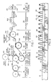
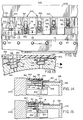
- Figures 1 and 2 of the drawings show the various stages in a machine for carrying out a wire lead forming and securing process according to one possible embodiment of the present invention.
- This process forms one preferred embodiment of a process involving continuously operable tools according to other embodiments of the present invention.
- the various components of the machine at successive stages in the process are suitably mounted on a support frame 200 or other mounting assembly as indicated schematically in the drawings.
- the basic steps in the operation include punching a series of indexing holes 10 in a carrier strip or ribbon 12 at a first stage 14 in the process.
- the carrier strip is suitably of cardboard or similar material of sufficient flexibility to be transported along the indicated path through the various stages in the process.
- the indexing holes are used in transporting the strip along the indicated path and maintaining it in the correct location relative to the various tools as it passes through the various stages of the process.
- the leads are reformed to shape the loops more accurately, and the shaped leads are then carried on the carrier strip to the fourth stage 24 where components 26 are fed into the successive loops so that they are gripped between the opposite arms of each loop at its narrower end 28.
- the loops carrying components are then transported to the soldering stage 30, where they are passed through flux 32, heated and then passed through a solder wave at 34 to secure the components to the opposite arms of each loop.
- the projecting end 38 of each loop is cut off to separate the leads, and the carrier tape carrying the finished components can then be tensioned and wound onto a storage reel, subsequent to an optional gross testing stage described below in connection with Figure 18.
- FIG. 3 of the drawings illustrates a hole punching apparatus 40 utilized in the first stage 14 of the process.
- a continuous length of carrier strip 12 is fed from a suitable supply roll (not shown) to the apparatus 40, where it is passed between two commonly driven rollers 42 and 44 which are rotatably mounted on frame 200 with their axes parallel.
- the roller 42 has a series of holes 46 spaced around its periphery, while the roller 44 has a series of radially projecting pins 48 at equivalent spacings which cooperate with roller 42 to project into the holes 46 at the closest point between the rollers, where they are spaced apart by a distance approximately equal to the thickness of the carrier strip, as shown in Figure 3.
- the pins will pierce a series of spaced holes 10 in the strip 12 as it passes between the rollers, and the pierced strip is directed from the first stage of the process to the second stage 16 as indicated in Figure 1.
- the carrier strip was of approximately 18 mm width and a thickness of 0 . 5 mm, and the indexing holes were of approximately 4 mm diameter at a spacing of about 1.26 cm.
- these dimensions may be varied according to the specific application and the required spacing between units to be secured to the carrier strip.
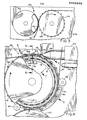
- the second stage of the process comprises a wire forming tool or apparatus 50 which is shown in detail in Figures 4 to 8.
- the apparatus 50 is a continuously operable tool comprising a rotatable assembly lying with at least part of its path of rotation in the path of the carrier strip.
- the assembly basically comprises a rotating drum 52 mounted on the frame 200 and having a series of wire forming stations 54 spaced around its periphery. In the preferred embodiment thirty wire forming stations 54 are provided at equal spacings around the periphery of the drum.
- Each wire forming station includes a forming die or slider 56 having a shaped cut out or indent 58, and an anvil device 60 of outline corresponding in shape to the cut out 58, as best shown in Figure 5.
- the slider has a tongue or lip 61 which projects forwardly over the cut-out as shown in Figure 6 and 7.
- a suitable drive assembly (not shown) is provided for rotating the drum 52.
- the forming die is mounted to slide back and forth axially across the outer surface of the drum, while the anvil device is mounted to move radially in and out between an inoperative position and an operative position.
- the inoperative position 62 shown at the left hand end of Figure 5 the forming die and anvil device are spaced apart to leave a gap 105 and the anvil device is retracted within the drum, and in the operative position 64 the anvil device projects out of the outer surface of the drum and is engaged within the cut-out 58 in the advanced forming die.
- the wire forming apparatus also includes a wire feeding assembly 66 including a wire feeder 68 for feeding wire 70 in the direction of a pick-up point 72 at or adjacent the uppermost or 12 o'clock position on the drum's periphery, and a cutter 74 for cutting the wire to a predetermined length.
- the wire feeding assembly is of a conventional type and also includes a wire tensioner and straightener (not shown in the drawings) and an optional wire oiler or cleaner.
- the wire itself may be of copper coated steel, for example, or other wire material suitable for forming the leads of electronic components.
- An actuating assembly 76 is also provided for reciprocating the forming die and anvil device at the various forming stations between their operative and inoperative positions.
- the actuating assembly comprises a first stationary cam surface 78 positioned adjacent the peripheral edge of the drum around at least part of its circumference for engaging the outer ends 80 of the forming dies as shown in Figures 5 to 7.
- a second stationary cam surface 81 is positioned within the drum as shown in Figure 8 for engaging the inner ends of the anvil devices as they rotate with the drum.
- the first cam surface 78 includes a retracting slot 82 for engaging retracting pins 84 projecting upwardly from the forming dies as they rotate past the three o'clock position, as indicated in Figure 4.
- a return roller or bearing 86 is rotatably mounted in contact with the outer surface of the drum at a position just past the six o'clock point to return the anvil devices to their inoperative position.
- the return roller may optionally be arranged to act on pins projecting from the wider end of each anvil device so that each anvil device is actually recessed slightly within the drum's surface in the inoperative position.
- a tape feeding assembly 88 which comprises a supply 90 of adhesive tape 92, and a tape heater 94.
- the adhesive tape 92 is fed from the supply 90 past the heater 94 to the drum, where it is urged with its adhesive face inwards against carrier strip 12 (see Figure 4) by means of a silicone roller 96 bearing against the tape at the three o'clock position of the drum.
- the pierced carrier strip 12 travels from the first stage 14 to a position just before 12 o'clock on the drum 52, where a series of indexing pins 98 projecting from the periphery of the drum at spaced intervals corresponding to one or more times the spacing between spaced indexing holes on the strip 12 engage in successive holes in the strip as the drum rotates past the pick-up point 72 to carry the strip around the drum to an exit point 100.
- the carrier strip is carried in a recess 102 around the right hand half of the drum periphery, as shown in Figures 6 and 7.
- the strip is carried around the drum for approximately 200 degrees to the exit point 100, which is at or just after the lowermost or six o'clock position.
- the carrier strip is directed around a take off roller 103 which may be a simple plastic drum or may have radially projecting indexing pins (not shown) which engage the indexing holes in the strip as it travels around the roller.
- the take-off roller 103 is rotated by a common drive assembly in contact with the drum at approximately the six o'clock position.
- the carrier strip here makes a 180 degree turn around take-off roller 103 before proceeding to the next station.
- a suitable drive assembly (not shown in the drawings) is provided for rotating the drum and take off roller continuously.
- the wire feeder will shoot a cut length of wire 104 (see Figures 4 and 5) transversely into the gap 105 between the forming die and anvil device, so that the wire is picked up or trapped in the gap and carried away as the drum continues to rotate.
- a radial step 106 in the outer periphery of the second cam surface will start to urge the anvil device outwardly to its operative position.
- an outwardly curved portion 108 on the first cam surface curving towards the drum will cause the forming die at that station to start travelling across the outer surface of the drum to grip the length of wire between it and the corresponding projecting anvil device.
- the wire will be bent between the opposed faces of the cut-out and anvil device to form a loop 18 of the shape shown in Figure 5 having a narrower inner end portion 28.
- the projecting lip 61 above the cut-out will ensure even, flat forming of the opposite arms of each loop of wire and give the wire no chance to twist or warp out of the bending plane.
- the first cam surface is shaped such that the forming die reaches its operative position between the twelve and three o'clock positions of the respective forming station. The bending will be completed approximately 30 degrees beyond the 12 o'clock position. A straight portion 112 of the cam surface then maintains the forming die in its operative position until the forming station reaches the retracting groove, to ensure that the wire shape is maintained until the free ends of the loop are taped to the carrier strip. This prevents spring action of the wire causing it to loose its shape.
- the retracting groove 82 is shaped and positioned to engage the retracting pins of successive forming dies as they reach the groove, and to pull the forming dies back into the inoperative position to release the formed loops of wire.
- each forming die is in the retracted, inoperative position just before its respective station reaches the exit point.
- the carrier strip is carried via indexing pins around the periphery of the drum adjacent the forming stations, such that when the successive lengths of wire are formed into loops their free ends 20 will lie over the adjacent edge of the strip 12.
- the adhesive tape 92 is urged by the roller 96 at the three o'clock position against the edge portion of the strip to secure the free ends of successive loops to the strip, so that when the forming die is retracted the secured loops are carried away from the drum by the carrier strip on the take off roller.
- successive lengths of wire are picked up at successive forming stations as they pass the pick up point, shaped into loops having narrowed end portions, and secured to a carrier strip to be carried away from the drum to the next stage in the process.
- a series of wire loops will be engaged at successive stations between the pick-up and exit points, and the wire forming process can proceed continuously with no need for intermittent operation.
- the spacing between adjacent stations on the drum is such that the successive cut lengths of wire directed to the pick-up point will not interfere with either the preceding or successive forming stations which will be positioned below the feed direction of wire feeder 68.
- the respective forming station is about 2 to 3 degrees past the pick up point when the length of cut wire is shot into place.
- anvil devices 60 ensures that they are retracted until they reach the pick-up point so that the left hand end of the fed length of wire does not bump into the adjacent anvil device left of the pick-up point.
- the wire feeder is timed and co-ordinated with the rotation of the drum 52 so as to fire a length of cut wire at the pick up point each time a forming station reaches the pick up point during rotation of the drum.
- the rotatable assembly in the preferred embodiment of the tool described above is a cylindrical drum, it may comprise any suitable assembly having an outer peripheral surface or track which follows a closed path when the assembly is rotated.
- the outer peripheral surface is positioned to lie in the path of workpieces around at least part of its path of rotation between the pick up and exit point.
- the rotatable assembly is preferably shaped so that the handling or wire forming station at the pick up point at any one time is raised above both the preceeding and successive wire forming station on the assembly.
- the pick up point is at or near the uppermost position on the drum.
- stationary cam surfaces have been described as the actuating assemblies for urging the forming dies and associated anvil devices between their inoperative and operative positions
- stationary cam tracks or rails may be provided in an alternative arrangement so that separate return devices such as the return groove and return roller are not required.
- the anvil devices need not be retracted but could remain continuously in their projecting, operative position, if the spacing between adjacent stations was sufficient to ensure that the cut length of wire fed to a station would not interfere with the preceeding or succeeding station.
- wire forming apparatus 50 has been described above as part of a continuous process for securing wire leads to electrical components, it will be understood that such a wire forming apparatus can be used in many alternative applications in which wires are to be bent into any chosen configuration, with suitable adjustment of the shapes of the cut-out 58 and anvil device 60.
- the indexing pins 98 and forming stations 54 on the drum are positioned such that the successive formed and taped lengths of wire are positioned between adjacent indexing holes 10 of the carrier strip.
- a spacing of the order of 1.25 cm between adjacent loops of wire was provided, but clearly alternative spacings may be provided for different applications according to the size of components to be secured to the carrier strip.
- the continuously operable wire forming tool allows a plurality of lengths of cut wire to be handled simultaneously while they are being transported along a predetermined path.
- the rate of wire forming can be increased significantly over an intermittently operated forming tool which is positioned at a single position in the workpiece path and only bends one wire at a time.
- This wire forming tool may therefore be of significant use in any wire forming operation, and not only in the forming of wire leads for electronic components.
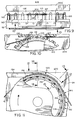
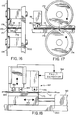
- the third stage of the process comprises a wire lead re-forming apparatus as best shown in Figures 9 and 10.
- the apparatus comprises a rotating drum 120 mounted on frame 200 and having a series of spaced generally V-shaped indents 122 defined between projections 124 and a stationary pusher plate 126 positioned above the drum 120 and having a slot 127 into which successive projections project as the drum rotates past the plate 126. Again the drum will be rotated by a suitable drive assembly (not shown).
- indexing pins 128 Spaced around the periphery of the drum are a series of indexing pins 128 positioned to engage in successive indexing holes in carrier strip 12 as it is fed onto the drum.
- the indexing pins are positioned to carry the strip 12 around the drum 120 with the narrow ends of the projecting loops of wire located in successive indents 122.
- the indents are of downwardly tapering width so that the pusher plate pushes the narrow end portions of the loops downwardly into the indents as shown in Figure 9 to squeeze the opposite arms of the narrow end portions together. This ensures that the spacing between the arms of each loop of wire at the narrow end 28 is slightly less than the component or chip size, taking into account possible manufacturing variations. After the squeezing operation the strip carrying the reformed loops is directed to the fourth stage 24 of the process.
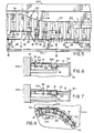
- the fourth stage 24 of the process comprises a component or chip insertion tool or apparatus 130 which is shown in Figures 11 to 15.
- the components 26, which may be any electronic components to which leads are to be applied, such as capacitors, transducers, resistors and the like, are supplied from a component feeder bowl 132, shown schematically in Figure 1, via a linear vibrator 134 to the component insertion tool.
- the insertion tool or apparatus 130 basically comprises a rotatable assembly or drum 136 having an annular indent or groove 138 around the right hand half of its peripheral surface, as shown in Figures 12,14 and 15, in which the carrier strip is guided from the point where it meets the drum to the exit point where it is guided away from the drum to the next stage of the process.
- the groove 138 has a series of spaced radially projecting indexing pins 140 which cooperate with the carrier strip 12 in the same manner as the indexing pins on the wire forming drum 52 to carry the strip 12 in the desired path around part of the drum as it rotates.
- the drum 136 has a series of spaced component insertion stations 142 spaced around its periphery. In a preferred embodiment of the invention thirty spaced stations are provided around the periphery of the drum, but a greater or lesser number may be provided in alternative applications.
- the drum has an axially orientated groove 144 in which a component pick up and feed slider 146 is provided.
- Each slider is movable axially in its respective groove between the inoperative position shown in Figure 14 and the operative position shown in Figure 15.
- each groove 144 is of stepped width, with a widened outer end portion 145 and opposed ledges or shoulders 147 on opposite sides of the groove between the wider portion and the narrower inner end portion in which the slider 146 rides.
- the sliders are each of width slightly less than that of the average component 26 and each have an upwardly facing open sided component receiving pocket 148, as best shown in Figures 14 and 15.
- the pocket 148 is defined between two upward projections or shoulders 150,152 which are spaced apart a sufficient distance to allow the average component to rest in the pocket as shown in Figures 12 and 14.
- the rearmost shoulder 152 is taller than the other shoulder and acts as a pusher.
- an actuating pin 1 54 projects downwardly from the inner or rear end of each slider 146.
- the actuating pins 154 cooperate with an actuating assembly comprising advance and return stationary cam surfaces 156 and 158 (see Figure 11) within the drum for moving the sliders between the operative and inoperative positions as the drum rotates.
- the carrier strip 12 carrying the wire loops 110 meets the drum at approximately the 9 o'clock position, as shown in Figures 1 and 11, where it is picked up by engagement of the indexing pins 140 in holes 10 such that the wire loops project into widened upper end portions of the successive grooves 144 above the sliders 146 (see Figures 12 to 15).
- the opposite arms of each loop rest on the opposed ledges or shoulders 147 of the respective groove on opposite sides of the slider.
- the width of the sliders is less than the loop gap at the wider end of the loop, so that each pusher shoulder 152 in the inoperative position of its slider will project upwardly between the opposite arms of each loop at its widest end as the loops are picked up at the pick up point on the drum in successive insertion stations as they rotate past the pick up point.
- the linear vibrator 134 comprises a linear track along which components are fed one by one to an outlet 160 which is located at or near to the uppermost or 12 o'clock point on the drum 136.
- a cover or tongue member 162 Projecting forwardly from the outlet end of the track across the drum circumference is a cover or tongue member 162, which may be of plastic or other suitable material and which is machined to fit snugly against the outer surface of the drum above the axial grooves.
- the cover member 162 extends for approximately 20 degrees around the drum circumference from the component insertion point.
- each pocket is set so that a component in the pocket will meet the opposite leads or arms of the respective loop at a plane which approximately halves the component in two.
- the actuating pin 154 will travel against a curved actuating surface of the cam 156 as shown in Figure 12 to urge the slider outwardly towards the advanced position shown in Figure 15.
- the slider at the right hand end of the portion of the drum shown in Figure 12 has just reached the advanced or operative position.
- the slider moves the component is pushed by pusher shoulder 152 towards the narrow end 28 of the loop, where the spacing between the opposite arms or leads is less than the width of the component.
- the component When the component reaches the narrow end of the loop it will be resiliently gripped between the opposite arms or leads 164, and will be carried out of the slider and away from the drum as the carrier strip is guided tangentially away from the drum at the exit point 166.
- the carrier strip is carried around the drum for a little more than 90 degrees before being directed away from it towards the next stage of the process.
- the outer periphery of the drum need not be circular but could define any closed path for the component insertion stations carried on the drum, for example oval or elongate.
- the assembly need not be a drum but could comprise a conveyer belt or continuous chain type of track which may be linear or substantially linear between the pick up point and exit point, with the assembly preferably curving away from the workpiece path at the exit point to return empty component insertion stations to the pick up point.
- the soldering stage includes fluxer 32 and a pre-heater 168 where the components are preheated to prevent damage from thermal shock.
- the pre- heater is arranged to be moved away from the wire loops and components automatically whenever the machine stops, to prevent damage to a component within the pre-heater for an excessive amount of time.
- the pre-heater comprises a heated piece of metal, similar to a soldering iron, having a slit through which the component passes.
- the pre-heater temperature is adjustable.
- the loops and carried components pass through a wave soldering device 34.
- Each chip-loop assembly kisses the solder wave and picks up liquid solder by adhesion. As the solder freezes or cools the leads contacting the opposite sides of the chip or component are secured to the component.
- the carrier strip 12 is directed through a cutting stage 36, shown in more detail in Figures 16 and 17.
- the component leaving the soldering stage still has a loop end 170 projecting beyond its outer edge, as seen in Figure 2, and thus the opposite leads 164 are short circuited.
- the projecting loop end 170 is cut off to separate the leads.
- the cutting stage 36 basically comprises a pair of circular knife blades 172,174 rotating in opposite directions with their bladed edges in contact at contact point 176, as shown in Figure 16.
- the carrier strip is guided in a linear path along a suitable guide 175 so that the projecting loop ends 170 of the component-loop assemblies are directed between the knife blades with the bladed edges contacting just beyond the outer edge 178 of the component.
- the projecting loop will pass between the knife blades and be cut off. Since the knife blades cannot overlap there is a risk that loops will not be completely cut off at this point, so a further blade 180 is provided beyond the circular blades which is pushed downwardly in the direction of the arrow in Figure 17 by a suitable actuator 181 as each component passes it to push off any remaining projecting loops.
- testing stage 182 illustrated in Figure 18, is provided following the cutting stage for gross testing of components for open and short circuits. Besides the wire feeder, this is the only part of the machine which operates intermittently. As shown in Figure 18, the testing stage comprises two test devices 184 and 186 which simultaneously test two successive components as they travel through the testing stage. The testing stage or station is driven back and forth in the direction of the arrow 190 in Figure 18 to test successive pairs of components without stopping the carrier strip 12.
- a hydraulic actuator 192 for example, may be used to drive the testing station back and forth.
- the test devices comprise spaced contacts 188 which contact the opposite leads of the components under test and provide output signals to a fault detector 194 which detects any open or short circuit in either of the tested components.
- a fault detector 194 which detects any open or short circuit in either of the tested components.
- the carrier strip carrying finished components will be tensioned and wound on a suitable take up reel.
- the machine incorporating continuously operating tools having a plurality of workpiece handling stations allowing continuous wire forming and component insertion operations can produce assembled electronic components at a relatively high rate and with reduced rates of faulty or unassembled components, for example as a result of components shaking loose prior to soldering to the wire leads.
- a machine according to this invention has been run at speeds of at least 200 components per minute at 1/2 inch spacings on the carrier strip and has achieved production rates of up to 300 finished components per minute with no problems.
- the closed end of the shaped loops of wire may be cut off prior to the component insertion stage, instead of after the soldering stage. Components can then be inserted into the narrow space between the projecting wire ends such that their outer edges slightly beyond the wire ends, ensuring that there are no projecting wire ends in the finished product.
- the machine therefore provides a relatively high speed and reliability of component production, and because of the continuously operable tools takes up relatively little shop floor space as compared to manual or other non continuous lead assembly production processes.
- the machine described above and the continuously operable tools have been described for use in manufadturing components with generally rectangular dimensions having parallel projecting leads, they may also be used in other applications involving wire forming, for example, either in the assembly of leads to electronic components of other shapes or in wire forming for other purposes.
- the wires may be shaped to have a cross over between which the opposed radial faces of disc- type components are retained.
Landscapes
- Engineering & Computer Science (AREA)
- Manufacturing & Machinery (AREA)
- Microelectronics & Electronic Packaging (AREA)
- Power Engineering (AREA)
- Automatic Assembly (AREA)
- Supply And Installment Of Electrical Components (AREA)
Applications Claiming Priority (2)
| Application Number | Priority Date | Filing Date | Title |
|---|---|---|---|
| US06/792,118 US4662066A (en) | 1985-10-28 | 1985-10-28 | Continuously operable tool for use in production line process |
| US792118 | 1985-10-28 |
Publications (2)
| Publication Number | Publication Date |
|---|---|
| EP0222549A2 true EP0222549A2 (fr) | 1987-05-20 |
| EP0222549A3 EP0222549A3 (fr) | 1988-05-25 |
Family
ID=25155856
Family Applications (1)
| Application Number | Title | Priority Date | Filing Date |
|---|---|---|---|
| EP86308371A Withdrawn EP0222549A3 (fr) | 1985-10-28 | 1986-10-28 | Outil susceptible de fonctionner continûment dans l'application dans un processus d'une ligne de production |
Country Status (3)
| Country | Link |
|---|---|
| US (1) | US4662066A (fr) |
| EP (1) | EP0222549A3 (fr) |
| JP (1) | JPS62236634A (fr) |
Families Citing this family (6)
| Publication number | Priority date | Publication date | Assignee | Title |
|---|---|---|---|---|
| FR2593320B1 (fr) * | 1986-01-21 | 1988-03-04 | Europ Composants Electron | Procede de fabrication d'un composant inductif pour report a plat |
| JPH04302125A (ja) * | 1991-03-29 | 1992-10-26 | Hitachi Zosen Corp | 箔巻電子部品製造装置 |
| EP1225663A1 (fr) * | 2001-01-23 | 2002-07-24 | Prodit GmbH | Dispositif de montage pour composants électriques |
| CN101434074B (zh) * | 2007-11-14 | 2012-03-28 | 鸿富锦精密工业(深圳)有限公司 | 剪切机和剪切方法 |
| EP2175457B1 (fr) * | 2008-10-09 | 2012-04-18 | Joinset Co., Ltd | Ensemble de puce en céramique |
| CN113725696B (zh) * | 2021-09-26 | 2023-01-03 | 四川华丰科技股份有限公司 | 一种用于弹性套夹的装配机构 |
Family Cites Families (10)
| Publication number | Priority date | Publication date | Assignee | Title |
|---|---|---|---|---|
| CA687166A (en) * | 1964-05-26 | H. Luther James | Capacitor assembly machine | |
| US3079957A (en) * | 1956-04-20 | 1963-03-05 | Cornell Dubilier Electric | Terminal wire forming and assembly apparatus for electrical components |
| US3091835A (en) * | 1956-04-20 | 1963-06-04 | Cornell Dubilier Electric | Capacitor manufacture |
| US3073007A (en) * | 1958-09-29 | 1963-01-15 | Sprague Electric Co | Method and means for assembling capacitors |
| US3080908A (en) * | 1959-03-13 | 1963-03-12 | Cornell Dubilier Electric | Terminal wire forming and assembly apparatus for electrical components |
| US3315331A (en) * | 1964-06-16 | 1967-04-25 | Cornell Dubilier Electric | Apparatus for manufacturing capacitors |
| US3394441A (en) * | 1966-11-03 | 1968-07-30 | Cornell Dubilier Electric | Method of manufacturing capacitors |
| JPS5335155A (en) * | 1976-09-11 | 1978-04-01 | Tdk Electronics Co Ltd | Method of manufacturing series of electronic parts |
| DE2948319C2 (de) * | 1979-11-30 | 1982-03-18 | Siemens AG, 1000 Berlin und 8000 München | Verfahren zum Anbringen und Befestigen von Stromzuführungsdrähten an elektrischen Bauelementen |
| FR2519509A1 (fr) * | 1981-12-31 | 1983-07-08 | Europ Composants Electron | Procede et dispositif pour la mise en boitier de composants electroniques |
-
1985
- 1985-10-28 US US06/792,118 patent/US4662066A/en not_active Expired - Fee Related
-
1986
- 1986-10-28 JP JP61256728A patent/JPS62236634A/ja active Pending
- 1986-10-28 EP EP86308371A patent/EP0222549A3/fr not_active Withdrawn
Also Published As
| Publication number | Publication date |
|---|---|
| US4662066A (en) | 1987-05-05 |
| EP0222549A3 (fr) | 1988-05-25 |
| JPS62236634A (ja) | 1987-10-16 |
Similar Documents
| Publication | Publication Date | Title |
|---|---|---|
| US5823082A (en) | Apparatus for manufacturing support members for razor blades | |
| CA1099905A (fr) | Traduction non-disponible | |
| US3971193A (en) | Machines for sequencing diverse components | |
| US4558981A (en) | Method and apparatus for assembling pronged binding strips with stacks of paper sheets or the like | |
| US4177554A (en) | Assembling leads to a substrate | |
| US4662066A (en) | Continuously operable tool for use in production line process | |
| US5725930A (en) | Supply feedstock for workpiece finishing machine | |
| EP0409068B1 (fr) | Appareil pour fabriquer des fermetures à glissière | |
| US4628600A (en) | Method and apparatus for producing electrical harnesses having multi-contact connectors and discrete wires | |
| US4205772A (en) | Terminal pin insertion machine | |
| US20020052244A1 (en) | Apparatus and method for manufacturing offset head nails | |
| US4003413A (en) | Machines for reforming and repackaging components | |
| EP0467593B1 (fr) | Méthode et appareillage pour le traitement d'une pluralité de terminaisons de câble | |
| CN101959628A (zh) | 双边和双处理子弹带 | |
| US3079957A (en) | Terminal wire forming and assembly apparatus for electrical components | |
| JPS6336160B2 (fr) | ||
| US3187972A (en) | Apparatus for automatically inserting electrical components | |
| US6405430B1 (en) | Workpiece moving methods | |
| US3893381A (en) | Envelope fastener attaching machine | |
| US3987528A (en) | Non-axial lead electrical component prepper-taper apparatus | |
| US4034893A (en) | Machines for sequencing diverse components with component separating and guiding surface | |
| US4452352A (en) | Apparatus for loading parts into bodies | |
| US3636610A (en) | Wire pull and tape machine | |
| US7383760B1 (en) | Bandoliered flechettes and method for manufacturing bandoliered flechettes | |
| GB2074967A (en) | Improvements in or relating to apparatus for loading parts into bodies |
Legal Events
| Date | Code | Title | Description |
|---|---|---|---|
| PUAI | Public reference made under article 153(3) epc to a published international application that has entered the european phase |
Free format text: ORIGINAL CODE: 0009012 |
|
| AK | Designated contracting states |
Kind code of ref document: A2 Designated state(s): AT DE FR GB |
|
| PUAL | Search report despatched |
Free format text: ORIGINAL CODE: 0009013 |
|
| AK | Designated contracting states |
Kind code of ref document: A3 Designated state(s): AT DE FR GB |
|
| STAA | Information on the status of an ep patent application or granted ep patent |
Free format text: STATUS: THE APPLICATION IS DEEMED TO BE WITHDRAWN |
|
| 18D | Application deemed to be withdrawn |
Effective date: 19890501 |
|
| RIN1 | Information on inventor provided before grant (corrected) |
Inventor name: TOMAN, HERBERT Inventor name: KOPECKY, FRIEDRICH |