EP0222600A2 - Dispositif d'alimentation du papier pour imprimantes - Google Patents
Dispositif d'alimentation du papier pour imprimantes Download PDFInfo
- Publication number
- EP0222600A2 EP0222600A2 EP86308668A EP86308668A EP0222600A2 EP 0222600 A2 EP0222600 A2 EP 0222600A2 EP 86308668 A EP86308668 A EP 86308668A EP 86308668 A EP86308668 A EP 86308668A EP 0222600 A2 EP0222600 A2 EP 0222600A2
- Authority
- EP
- European Patent Office
- Prior art keywords
- paper
- feed motor
- stack
- feed
- feed roller
- Prior art date
- Legal status (The legal status is an assumption and is not a legal conclusion. Google has not performed a legal analysis and makes no representation as to the accuracy of the status listed.)
- Granted
Links
Images


Classifications
-
- B—PERFORMING OPERATIONS; TRANSPORTING
- B41—PRINTING; LINING MACHINES; TYPEWRITERS; STAMPS
- B41J—TYPEWRITERS; SELECTIVE PRINTING MECHANISMS, i.e. MECHANISMS PRINTING OTHERWISE THAN FROM A FORME; CORRECTION OF TYPOGRAPHICAL ERRORS
- B41J13/00—Devices or arrangements of selective printing mechanisms, e.g. ink-jet printers or thermal printers, specially adapted for supporting or handling copy material in short lengths, e.g. sheets
- B41J13/0009—Devices or arrangements of selective printing mechanisms, e.g. ink-jet printers or thermal printers, specially adapted for supporting or handling copy material in short lengths, e.g. sheets control of the transport of the copy material
- B41J13/0018—Devices or arrangements of selective printing mechanisms, e.g. ink-jet printers or thermal printers, specially adapted for supporting or handling copy material in short lengths, e.g. sheets control of the transport of the copy material in the sheet input section of automatic paper handling systems
-
- B—PERFORMING OPERATIONS; TRANSPORTING
- B41—PRINTING; LINING MACHINES; TYPEWRITERS; STAMPS
- B41J—TYPEWRITERS; SELECTIVE PRINTING MECHANISMS, i.e. MECHANISMS PRINTING OTHERWISE THAN FROM A FORME; CORRECTION OF TYPOGRAPHICAL ERRORS
- B41J11/00—Devices or arrangements of selective printing mechanisms, e.g. ink-jet printers or thermal printers, for supporting or handling copy material in sheet or web form
- B41J11/48—Apparatus for condensed record, tally strip, or like work using two or more papers, or sets of papers, e.g. devices for switching over from handling of copy material in sheet form to handling of copy material in continuous form and vice versa or point-of-sale printers comprising means for printing on continuous copy material, e.g. journal for tills, and on single sheets, e.g. cheques or receipts
- B41J11/52—Apparatus for condensed record, tally strip, or like work using two or more papers, or sets of papers, e.g. devices for switching over from handling of copy material in sheet form to handling of copy material in continuous form and vice versa or point-of-sale printers comprising means for printing on continuous copy material, e.g. journal for tills, and on single sheets, e.g. cheques or receipts in which one paper or set is moved transversely relative to another
- B41J11/53—Devices for holding in place one paper or set during replacement of one or more of the auxiliary papers or sets
-
- B—PERFORMING OPERATIONS; TRANSPORTING
- B41—PRINTING; LINING MACHINES; TYPEWRITERS; STAMPS
- B41J—TYPEWRITERS; SELECTIVE PRINTING MECHANISMS, i.e. MECHANISMS PRINTING OTHERWISE THAN FROM A FORME; CORRECTION OF TYPOGRAPHICAL ERRORS
- B41J13/00—Devices or arrangements of selective printing mechanisms, e.g. ink-jet printers or thermal printers, specially adapted for supporting or handling copy material in short lengths, e.g. sheets
- B41J13/10—Sheet holders, retainers, movable guides, or stationary guides
Definitions
- the present invention relates to a device for feeding a paper to a paper feeding mechanism of a printer, for printing on the paper while the paper is supported by a platen.
- a printer equipped with an automatic sheet feeder which has a paper stacker for storing a stack of cut sheets and is adapted to automatically feed the cut sheets one after another from the paper satcker toward the platen of printer, when the platen is placed in an automatic feed mode.
- the printer equipped with such an automatic sheet feeder may be switched, upon manipulation of a suitable operator-controlled member, from the automatic feed mode to a manual feed mode wherein the printer is loaded with a cut sheet which has been manually inserted by the operator.
- the automatic sheet feeder is arranged such that the top of the stack of cut sheets is held in pressed contact with a feed roller of the sheet feeder, so that the top sheet is fed from the paper stacker.
- a paper feeding device for feeding a paper to a printer wherein the paper is fed by paper feeding means driven by a paper feed motor, for printing on the paper by a print head while the paper is supported by a platen, comprising: a paper stacker for storing a stack of paper sheets; a feed roller disposed for contact with a top of the stack of sheets, and rotated for feeding a top sheet of the stack from the paper stacker; first passage means for defining a first paper path for directing the top sheet fed by the feed roller, to the paper feeding means; second passage means for defining a second paper path for directing another sheet of paper to the paper feeding means without the above-indicated another sheet passing the feed roller; a transmission mechanism disposed between the feed roller and the paper feed motor, for transmitting a rotary motion of the paper feed motor to the feed roller; and a cut-off mechanism disposed in the transmission mechanism, and manually operated to a cut-off position in which transmission of the rotary motion of the feed
- the cut sheets are fed toward the platen one after another from the paper stacker by the feed roller operatively connected to the paper feeding motor by means of the transmission mechanism, while the printer is placed in an automatic feed mode.
- the cut-off mechanism Upon switching of the feed mode from the automatic mode to the manual mode, the cut-off mechanism is manually operated to its cut-off position to disconnect the feed roller from the paper feed motor. Therefore, the cut sheet manually inserted along the second paper path can be advanced toward the platen by the paper feeding means of the printer driven by the paper feed motor, while the feed roller of the paper feeding device is operatively disconnected from the paper feed roller.
- the instant paper feeding device permits easy changeover between an automatic feed mode for automatically feeding cut sheets from the paper stacker one after another toward the platen along the first paper path, and a manual feed mode wherein a cut sheet may be manually inserted along the second paper path. Further, the manipulation of the operator-controlled cut-off mechanism upon selection of the manual feed mode will automatically cause the transmission mechanism to be disconnected, so as to cut off power transmission from the paper feeding motor to the feed roller of the paper feeding device. Hence, the cut-off mechanism prevents an unnecessary load which would otherwise be applied to the paper feeding motor.
- the transmission mechanism comprises a gear train including a first gear, a second gear and a third gear which are rotatable about a first axis, a second axis and a third axis, respectively
- the cutt-off mechanism comprises an operator-controlled lever which is supported pivotally about the first axis.
- the lever supports the second gear for rotation about thed second axis, and is pivotally movable between a connected position for operative connection of the second gear with the third gear, and a disconnected position for operative disconnection of the second gear from the third gear.
- the cut-off mechanism further comprises biasing means for biasing the lever toward the connected position, and lock means for locking the lever in the disconnected position, against a biasing force of the biasing means.
- the lock means includes a protrusion extending from the lever parallel to the first axis, and a stationary member disposed adjacent to the lever.
- the stationary member has an arcuate elongate hole formed along a circular arc which is described by the protrusion when the lever is pivotally moved about the first axis.
- the protrusion engages the arcuate elongate hole with a slight clearance therebetween in a direction perpendicular to the circular arc.
- the stationary member includes a locking portion which gives the arcuate elongate hole a constricted portion near one of opposite ends thereof which corresponds to the second position of the lever.
- the constricted portion has an original size slightly smaller than the protrusion in the direction.
- the locking portion is elastically deformed to expand the constricted portion, thereby permitting the protrusion to pass the constricted portion to the above-indicated one end of the arcuate elongate hole when the protrusion is forced against the locking portion.
- the locking portion is restored to an original position to cause the expanded constricted portion to recover the original size, thereby locking the protrusion at the above-indicated one end of the arcute elongate hole, after the protrusion has passed the expanded constricted portion of the elongate hole.
- the paper feed motor is operable in opposite directions which consist of a foward direcion for operating said paper feeding means in a paper feeding direcion, and a reverse direction opposite to said forward direction.
- the feed roller is rotated through the transmission mechanism in a direction to feed the top sheet from the paper stacker when the feed motor is rotated in the reverse direction thereof, the paper feeding device further comprising detecting means for sensing the cutt-off position of the cut-off mechanism; and motor control means connected to the feed motor and the detecting means.
- the motor controller means is adapted to operate the feed motor in the reverse direction by a predetermined angular amount, and to subsequently operate the feed motor in the forward direction, when the cut-off position of the cut-off mechanism is not detected by the detecting means.
- the motor control means operates the feed motor in the forward direction without initially operating the feed motor in the reverse direction,
- the transmission mechanism comprises a gear train including a first gear, a second gear and a third gear which are rotatable about a first axis, a second axis and a third axis, respectively
- the cutt-off mechanism comprises an operator-controlled lever which is supported pivotally about the first axis.
- the lever supports the second gear for rotation about thed second axis, and is pivotally movable between a first position for operative connection of the second gear with the third gear, and a second position for operative disconnection of the second gear from the third gear.
- the detector means is operable to detect at least one of the first and second positions of the operator-controlled lever.
- the paper feeding means further comprises a pair of paper advancing rollers disposed in contact with each other at outer circumferential surfaces thereof, between the feed roller and the paper feeding means of the printer.
- the pair of paper advancing rollers are connected to the feed motor such that the avancing rollers are rotated in a paper advancing direction to advance the top sheet toward the paper feeding means when the feed motor is operated in the forward direction, and are rotated in an opposite direction opposite to the paper advancing direction, so as to prevent a leading edge of the top sheet fed by the feed roller, from passing therethrough toward the paper feeding means, thereby causing a leading portion of the top sheet to be buckled between the pair of paper advancing rollers and the feed roller.
- the second paper path may be advantageously arranged so as to lead to the pair of paper advancing rollers.
- the paper feeding means may further comprises an earth member which is made of an electrically conductive material and which is connected to the ground.
- the earth member is disposed such that the buckled leading portion of the top sheet contacts the earth member.
- the earth member may consist of a generally planar partition wall member which constiute parts of the first and second passage mean, and which separates the first and second paper paths from each other.
- the partition wall member being disposed so that not only the top sheet, but also the above-indicated another sheet fed along the second paper path can contact the partition wall member.
- the paper feeding device further comprises: converting means including a pinion operatively connected to the paper feed motor, and a rack member engaging the pinion for converting bidirectional rotating movements of the pinion into linear reciprocating movements; a pushing member disposed on one of opposite sides of the stack of sheets on the paper stacker, remote from the feed roller.
- the pushing member is moved by the linear reciprocaing movemens of the rack member, between an advanced position thereof for forcing the stack of sheets against the feed roller, and a retracted position thereof in which the stack of paper is spaced away from the feed roller; and a clutch disposed between the pinion and the paper feed motor, for disconnecting the pinion from the paper feed motor and thereby stopping an advancing movement of the pushing member when a contact pressure applied by the pushing member between the stack of sheets and the feed roller exceeds a predetermined upper limit.
- Another object of the invention is to provide a paper feeding device for a printer, which has an automatic sheet feeder, and which has means for smooth and reliable feeding of cut sheets from a paper stacker of the sheet feeder to paper feeding means incorporated in the printer.
- a paper feeding device for feeding a paper to a printer wherein the paper is fed by paper feeding means driven by a paper feed motor, for printing on the paper by a print head while the paper is supported by a platen, comprising: a paper stacker for storing a stack of paper sheets; a feed roller disposed for contact with a top of the stack of sheets and rotated for feeding a top sheet of the stack from the paper stacker; pushing means operable between an advanced position thereof for forcing the stack of sheets against the feed roller, and a retracted position thereon in which the stack of sheets is spaced away from the feed roller; a pair of paper advancing rollers disposed in contact with each other at outer circumferential surfaces thereof, between the feed roller and the printer; a transmission mechanism for transmitting a rotary motion of the paper feed motor to the feed roller and the paper advancing rollers; and control means for operating the paper feed motor in one of opposite directions to rotate the feed roller in a paper feeding direction
- the control means stops the paper feed motor when the leading end of the top sheet has abutted on the nip of the paper advancing rollers, and subsequently operates the paper feed motor in the other direction to rotate the paper advancing rollers in a paper advancing direction for feeding the top sheet toward the paper feeding means of the printer, by a predetermined distance.
- the pushing means is placed in the advanced position when the paper feed motor is operated in the above-indicated one of the opposite directions, and in the retracted position when the paper feed motor is operated in the other direction.
- the paper feeding device further comprises converting means including a pinion operatively connected to the paper feed motor, and a rack member engaging the pinion for converting bidirectional rotating movements of the pinion into linear reciprocating movements.
- the paper feeding device further comprises a clutch disposed betwen the pinion and the paper feed motor.
- the pushing means is disposed on one of opposite sides of the stack of sheets on the paper stacker, remote from the feed roller. The pushing means is moved by the linear reciprocating movements of the rack member, between the advanced and retracted positions.
- the clutch is adapted to disconnect the pinion from the paper feed motor and thereby stop an advancing movement of the pushing means when a contact pressure applied by the pushing means between the stack of sheets and the feed roller exceeds a predetermined upper limit.
- a further object of the invention is the provision of a paper feeding device for a printer, which has an automatic sheet feeder, and which has means for maintaining a suitable contact pressure between the feed roller of the sheet feeder and a stack of cut sheets stored on the paper stacker of the sheet feeder, irrespective of a thickness of the paper stack.
- a printer wherein the paper is fed by paper feeding means driven by a paper feed motor, for printing on the paper by a print head while the paper is supported by a platen, comprising: a paper stacker for storing a stack of paper sheets; a feed roller disposed opposite to a top of the stack of the sheets and operatively connected to the paper feed motor, for rotation thereof by the feed motor for feeding a top sheet of the stack from the paper stacker; converting means including a pinion operatively connected to the feed mottor, and a rack member engaging the pinion for converting a rotating movement of the pinion into a movement; a pushing member disposed on one of opposite sides of the stack of sheets on the paper stacker, remote from the feed roller, the pushing member being advanced by the movement of the rack member, for forcing the stack of sheets against the feed roller; and a cluch disposed between the pinion and the paper feed motor, for disconnecting the pinion from the paper feed motor when
- the top sheet of the stack pressed in contact with the feed roller by the pushing member is fed by rotation of the feed roller toward the paper feeding means of the printer.
- An advancing movement of the pushing member toward the feed roller is stopped upon disconnection cf the pinion from the feed motor by the clutch.
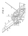
- a printer equipped with a paper feeding device wherein a platen 2 is rotatably supported by a frame 100 of the printer, at their opposite small-diameter end portions 2a.
- a cut sheet of paper PS or PS' is fed round the platen 2, so that the portion of the cut sheet PS or PS' at which printing occurs is supported by the platen 2.
- the frame 100 has rear portions defining a paper inlet 2b behind the platen 2, and front portions which support a guide rod 3 and a guide rail 4 such that the rod and rail 3, 4 extend parallel to the platen 2.
- the cut sheet PS or PS' is fed through the paper inlet 2b toward the platen 2.
- a carriage 5 is slidably supported by the guide rod and rail 3, 4 so that the carriage 5 is reciprocable along the platen 2 in the right and left directions.
- the carriage 5 carries a print head 6 mounted thereon. Printing is effected on the cut sheet PS or PS' by the print head 6 while the carriage 5 is reciprocated along the platen 2.
- a stepping motor 7 used as a paper feed motor.
- the motor 7 is connected to the platen 2 via a gear 9 fixed to the output shaft of the motor 7, and a gear 10 which is fixed to the right-hand side end portion 2a of the platen 2, in mesh with the gear 9.
- the paper feed stepping motor 7 is operated intermittently to rotate the platen 2 in the clockwise direction (in Fig. 1) or forward feeding direction, by means of the gears 9, 10, for advancing the cut sheet PS or PS ' by a predetermined line-to-line distance each time a line of characters is printed on the cut sheet.
- the paper feed motor 7, platen 2 and gears 9, 10 constitute a major part of the paper feeding means of the printer.
- the paper feeding device is removably mounted on the printer frame 100, such that the device is located substantially above the platen 2.
- a roller shaft 12 extends between, and is rotatably supported by, right and left side plates la, lb of a frame 1 of the paper feeding device.
- the roller shaft 12, which has a plurality of paper ejection rollers 11, is positioned above a paper outlet 2c formed in the printer frame 100.
- the cut sheet PS or PS' printed while supported by the platen 2 is ejected through a paper exit 13 formed in the frame 1.
- the printed cut sheets PS, PS' ejected through the paper exit 13 are stacked on the paper support 14.
- Two parallel roller shafts 17, 18 extend between, and are rotatably supported by, the right and left side plates la, lb, such that the shafts 17, 18 are located above the paper inlet 2b.
- These roller shafts 17, 18 have a plurality of paper advancing rollers 15, 16, respectively. These advancing rollers 15, 16 are held in contact with each other at their outer circumferential surfaces.
- the roller shaft 17 is positively driven, while the roller shaft 18 is freely rotatable. With the advancing rollers 15 rotated by the roller shaft 17 in the counterclockwise direction as seen in Fig. 1, the cut sheet PS fed from a paper stacker 19 is advanced toward the platen 2.
- the paper stacker 19 which stores the cut sheets PS in a stack, is disposed such that it extends in a rear upward direction from a portion of the frame 1 adjacent to the advancing rollers 15, 16. As described in greater detail, the cut sheets PS stored in the paper stacker 19 are fed toward the nip of the advancing rollers 15, 16, one after another while the printer is placed in an automatic paper feed mode.
- a paper guide plate 21 which extends between the paper inlet 20 and the advancing rollers 15, 16, passing near the lower end of the paper stacker 19.
- This guide plate 21 is made of an electrically conductive material and connected to the ground. The guide plate 21 is arranged so that the cut sheet PS fed from the paper stacker 19 or the cut sheet PS I manually inserted through the paper inlet 20 will contact the guide plate 21 while the cut sheet P S or PS' is fed toward the nip of the advancing rollers 15, 16.
- This guide plate 21 not only serves as a partition wall partially defining a first paper path 55 and a second paper path 56, but also as an earth member for discharging or eliminating static electricity charged on the cut sheets PS, PS'.
- the first paper path 55 extends between the lower end of the paper stacker 19 and the nip of the advancing rollers 15, 16, while the second paper path extends between the paper inlet 20 and the nip of the advancing rollers 15, 16.
- the partition wall 21 whose lower end is positioned above the advancing rollers 15, 16, separates the first and second paper paths 55, 56 from each other.
- the first and second paper paths 55, 56 merge at the advancing rollers 15, 16, into a single comman paper path leading to the platen 2.
- a roller shaft 22 is rotatably supported by the right and left side plates la, lb of the frame 1 of the paper feeding device, such that the roller shaft 22 extends parallel to the advancing rollers 15, 16 and platen 2, across the width of the paper stacker 19.
- the roller shaft 22 has a pair of right and left feed rollers 23, 23 mounted thereon via respective sleeves 24, 24, so that the feed rollers 23, 23 are rotatable with the shaft 22, and are slidably movable on the shaft 22 for adjustment of an axial distance therebetween.
- the two feed rollers 23, 23 are positioned opposite to the bottom of the paper stacker 19 (which will be described), so that the feed rollers 23, 23 may be held in pressed contact with the top of the paper stack PS stored in the stacker 19 (with the top sheet PS of the stack).
- the rear portion of the frame 1 has a transverse recessed portion 25 which is disposed behind the lower portion of the paper stacker 19, so as to extend parallel to the roller shaft 22.
- This transverse recessed portion 25 there are slidably received lower portions 26d of a pair of right and left paper receiver members 26, 26 each having an L-shaped cross section.
- the two paper receiver members 26, 26, which constitute the paper stacker 19, correspond to the pair of feed rollers 23, and are movable relative to each other.
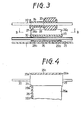
- Each receiver plate 26 has a bottom wall 26a on which the paper stack PS is placed, and a side wall 26b. With the receiver members 26 suitably positioned relative to each other, a distance between the side walls 26b is adjusted depending upon the width of the cut sheets PS. As shown in Figs.
- each side wall 26b has a rectangular aperture 27 and a U-shaped engagement portion 28.
- Each sleeve 24 for supporting each feed roller 23 on the roller shaft 22 is held in engagement with the corresponding U-shaped engagement portion 28, such that a pair of flanges formed on the sleeve 24 prevents a relative movement between the sleeve 24 and the corresponding receiver member 26 in the axial direction of the roller shaft 22.
- This arrangement permits the feed rollers 23 to be moved together with the paper receiver plates 26, for adjustment of the distance between the feed rollers 23 to suit the specific width of the cut sheets PS.
- a pushing member 29 having a planar substantially rectangular shape is provided opposite to each feed roller 23, that is, on one side of the paper stack PS remote from the feed roller 23.
- the pushing member 29 has three lugs 29a at the corresponding three corners. These three lugs 29a engage the opposite edges of the corresponding rectangular aperture 27, and the edge of a lower wall portion 26c of the receiver member 26.
- the pushing member 29 is movable relative to the corresponding receiver plate 26 and feed roller 23.
- Each pushing member 29 has a pair of spaced-apart legs 29b on its rear surface remote from the feed roller 23.
- an actuator rod 30 extends parallel to the roller shaft 22, so as to penetrate the legs 29b of the right and left pushing members 29.
- This actuator rod 30 is adapted to be movable toward and away from the feed rollers 23 between an advanced position in which the top of the paper stack PS on the stacker 19 is held in pressed contact with the feed rollers 23, and a retracted position in which the paper stack PS is spaced away from the feed rollers 23.
- the top sheet PS of the paper stack is fed by the feed rollers 23 rotating in the counterclockwise direction (in Fig. 1), from the paper stacker 19 toward the pair of advancing rollers 15, 16, along the first paper path 55.
- a power transmission mechanism 31 is provided between the paper feed motor 7 and the feed rollers 23, in order to transmit a rotary motion of the feed motor 7 to the feed rollers 23.
- the small-diameter end portion 2a of the platen 2, the roller shaft 12 for the ejection rollers 11, and the roller shaft 17 for the advancing rollers 15, have gears 32, 33 and 34, respectively, fixed at their left ends.
- Intermediate gears 35 and 36 are freely rotatably supported on the left side plate la, such that the gear 35 meshes with the gears 32 and 33, while the gear 36 meshes with the gears 33 and 34.
- the roller shaft 17 for the advancing rollers 15 has a gear 37 fixed to its right end, and the roller shaft 22 has a gear 38 freely rotatably mounted at its right end.
- Intermediate gears 39, 40 are freely rotatably supported on a shaft 41 fixed to the right side plate lb of the frame 1.
- the intermediate gear 39 meshes with the gear 37.
- a changeover lever 42 is supported pivotally by the shaft 41.
- the changeover lever 42 supports an intermediate gear 43 in a freely rotatable manner, such that the gear 43 meshes with the gears 38 and 40.
- the roller shaft 22 has a pair of rotors 44 fixedly mounted on the opposite ends. Each rotor 44 has a pinion 45 integrally formed at its axially intermediate portion.
- a spring clutch 46 is disposed between the right-hand side rotor 44 and the gear 38, for transmitting a rotary motion of the gear 38 to the right-hand side rotor 44, to thereby rotate the roller shaft 22 and the feed rollers 23.
- racks 47a of a pair of rack members 47 are held in engagement with the respective pinions 45 of the two rotors 44.
- the rack members 47 are connected at their lower ends to the opposite ends of the actuator rod 30, so that the rack members 47 are moved by the actuator rod 30.
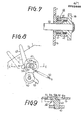
- the pinions 45 and the rack members 47 constitute a converter mechanism generally indicated at 48, for converting bidirectional rotating movements of the pinions 45 into linear reciprocating movements of the rack members 47. More specifically referring to Figs. 1, 5 and 6, the rotation of the platen 2 in the direction P upon operation of the feed motor 7 in the reverse direction will cause the pinions 45 and feed rollers 23 in the directions indicated by arrows in the figures, via the gears 32-40, 43, etc. With the rotating movements of the pinions 45, the rack members 47 are linearly moved in the upward direction, together with the actuator rod 30, whereby the pushing members 29 are moved toward the feed rollers 23 (to their advanced positions).
- the changeover lever 42 and the intermediate gear 43 on the lever 42 constitute a cut-off mechanism 49 which, when placed in its cut-off position, interrupts the operative connection between the feed rollers 23 (roller shaft 22) and the feed motor 7.
- the changeover lever 42 is biased in the clockwise direction by a tension spring 50 which is fixed at its one end to the right side plate la, and at its other end to the lever 49. That is, the tension spring 50 holds the changeover lever 42 in its first position (indicated in solid lines in Figs. 6 and 8) in which the intermediate gear 43 on the lever 42 engages the gear 38 on the roller shaft 22.
- This first position of the changeover lever 42 is selected when the printer is operated in an automatic paper feed mode.
- the right side plate lb of the frame 1 has a generally arcuate elongate hole 51 formed adjacent to the changeover lever 42, along a circular arc which is described by a protrusion in the form of a pin 52 formed on the inner surface of the pivotally supported changeover lever 42.
- the elongate hole 51 has an enlarged portion 51a at its one end corresponding to the first position of the changeover lever 42, and a constricted portion 51b near the other end corresponding to a second position of the changeover lever 42.
- the constricted portion 51b is partially defined by a locking tab which is formed on the side plate lb so as to protrude inwardly of the hole 51.
- the lever 42 When the lever 42 is installed, its pin 52 is brought into engagement with the arcuate hole 51 after a large-diameter head 52b of the pin 52 is inserted through the enlarged portion 51a.
- the pin 52 has a diameter which is slightly smaller than a size of the arcuate elongate hole 52 as measured between the enlarged and constricted portions 51a and 51b, in the direction perpendicular to the arc of the hole 52, so that the pin 52 engages the elongate hole 51 with a slight clearance therebetween.
- the changeover lever 42 is pivoted with its pin 52 guided in the arculate elongate hole 51 between its first and second positions.
- the cut-off mechanism 31 is placed in its cut-off position. This cut-off position of the mechanism 31, i.e., the second position of the changeover lever 42 is selected when the printer is placed in the manual paper feed mode.
- the changeover lever 42 has an operating arm 53 formed so as to extend from a portion adjacent to the shaft 42.
- This switch 54 is opened and closed by the operating arm 53, depending upon the currently selected position of the changeover lever 42. Namely, the detecting switch 54 generates a signal indicative of the currently selected position of the cut-off mechanism 49, or indicative of the currently selected one of the automatic and manual paper feed modes of the printer.
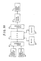
- the control system includes a central processing unit (CPU) 61, and a read-only memory (ROM) 62 and a random-access memory (RAM) 63 which are connected to the CPU 61.
- the ROM 62 stores various control programs for controlling the operation of the printer
- the RAM 63 stores various data such as the number of stepping pulses of the paper feed motor 7 (stepping motor) necessary to feed the cut sheet PS from the paper stacker 19 along the first paper path 55 by a predetermined distance, and the number of stepping pulses of the motor 7 necessary to advance the cut sheet PS from the paper stacker 19, or the manually inserted cut sheet PS' by a predetermined distance.
- the CPU 61 is connected via an input interface 65 to the previously indicated detecting switch 54, and to a paper feeding switch 64 which is provided on the frame 1 in order to start loading the printer with the new cut sheet PS or PS I. Namely, the signals from the switches 54, 64 are received by the CPU 61.
- the paper feed motor 7 is connected to the CPU 61, via an output interface 66 and a motor driver 67 which are connected between the CPU 61 and the feed motor 7. The feed motor 7 is turned on and off according to drive or stop signals generated by the CPU 61.
- step Sl the CPU 61 executes step Sl to check if the paper feeding switch 64 is in the ON position, i.e., whether a paper feeding command to effect a paper loading operation is present or not. If the paper feeding switch 64 has been turned on, the CPU 61 goes to step S2 to check if the mode detecting switch 54 is in the ON position, i.e., if the printer is in the automatic paper feed mode, or not.
- step S3 the paper feed motor 7 is operated in the reverse direction.
- step S4 the CPU 61 executes step S4 to check if the feed motor 7 has been operated by the predetermined number of steps which is stored in the RAM 63. Steps S3 and S4 are repeatedly executed until the predetermined number of steps has been reached.
- the operation of the feed motor 7 in its reverse direction causes the platen 2 to be rotated in the clockwise direction P (opposite to the paper advancing direction Q) as indicated in Figs. 1 and 5, whereby the roller shaft 22 is rotated in the direction indicated by arrow in Figs. 5 and 6, via the transmission mechanism 31 which is not disconnected by the cut-off mechanism 49.
- the feed rollers 23 on the roller shaft 22 are rotated in the counterclockwise direction (in Fig. 1).
- the rotation of the pinions 45 at the opposite ends of the roller shaft 22 will cause the pair of rack members 47 to be moved upward, whereby the pair of pushing members 29 are advanced in order to force the paper stack PS on the paper stacker 19, against the feed rollers 23.
- the top of the paper stack PS is pressed in contact with the feed rollers 23 by the pushing members 29. Consequently, the top sheet Ps of the paper stack in the stacker 19 is fed by the feed rollers 23, along the first paper path 55, toward the paper advancing rollers 15, 16. Since the advancing rollers 15, 16 are now rotated in the directions indicated by arrow in Fig. 1, i.e., in the counter paper-advancing direction, the leading end of the cut sheet PS will not pass the nip of the advancing rollers 15, 16. In other words, the cut sheet PS is stopped with its leading edge held in abutting contact with the nip of the advancing rollers 15, 16.
- the contact pressure between the paper stack PS and the feed rollers 23 is increased as the pushing members 29 are advanced toward the feed rollers 23, it is noted that when the contact pressure exceeds a predetermined upper limit, the spring clutch 46 shown in Figs. 2 and 7 is disengaged to disconnect the right-hand side rotor 44 from the rotating gear 38, and thereby stop the advancing movement of the pushing memers 29.
- the contact pressure between the paper stack PS and the feed rollers 23 can be maintained at a suitable level, irrespective of the number of the cut sheets PS of the paper stack on the paper stacker 19. This assures reliable feeding actions of the feed rollers 23 to feed the top sheet PS from the paper stacker 19.
- steppg pulses to operate the feed motor 7 in the reverse direction is determined so that the leading end portion of the cut sheet PS fed by the feed rollers is buckled by a suitable amount with the leading edge stopped by the advancing rollers 15, 16, as depicted in two-dot chain line in Fig. 1.
- the leading portion of the cut sheet PS is held in contact with the guide plate 21 which serves as an earth member for discharging the static electricity of the cut sheet PS or PS'.
- the number of stepping pulses to operate the feed motor 7 in the forward direction is determined so that the cut sheet PS is advanced round the platen 2, as indicated in dashed line in Fig. 1, until the first line to be printed on the sheet PS is located between the platen 2 and the print head 6. That is, the feed motor 7 is turned off when the cut sheet PS is advanced to the desired printing start position. Since the leading edge of the cut sheet PS fed from the paper stacker 19 is determined by the paper advancing rollers 15, 16, the operation of the feed motor 7 by the predetermined steps permits the cut sheet PS to be advanced exactly to the predetermined printing start position.
- the printer is set ready for printing on the cut sheet PS by the print head 6 with the carriage 5 being reciprocated along the platen 2, and with the platen 2 being rotated in the paper advancing direction Q to advance the cut sheet PS by a predetermined line-to-line distance at the end of printing of each line.
- the printed leading portion of the cut sheet PS is ejected through the paper exit 13, by the rotation of the ejection rollers 11.
- step S2 if the checking in step S2 reveals that the mode detecting switch 54 is placed in the OFF position (the printer is placed in the manual paper feed mode) with the changeover lever 42 set in the second position indicated in two-dot chain line in Figs. 6 and 8, the CPU 61 skips steps S3 and S4 to step S5.
- this manual paper feed mode the cut sheet PS' is manually inserted through the paper inlet 20, and is fed along the second paper path 56 indicated in one-dot chain line in Fig. 1, until the leading edge abuts on the nip of the advancing rollers 15, 16. Since the cut sheet PS' is guided by the guide plate 21, the static electricity of the sheet PS' is eliminated.
- the paper feeding switch 64 is turned on, and the feed motor 7 is operated in the forward direction by the predetermined number of steps, in steps S5 and S6.
- the cut sheet PS' is advanced by the advancing rollers 15, 16, and is eventually fed round the platen 2 to the predetermined printing start position.
- the changeover lever 42 is placed in its second position, that is, the cut-off mechanism 31 is placed in its cut-off position in which the intermediate gear 43 on the lever 42 is separated from the gear 38 on the roller shaft 22.
- the rotary motion of the feed motor 7 is not transmitted to the roller shaft 22, and the feed rollers 23 remain at rest while the pushing members 29 remain at their retracted position.
- the cut-off mechanism 31 was not provided, or if the feed motor 7 was operatively connected to the roller shaft 22 even in the manual paper feed mode, an additional load to rotate the roller shaft 22 and advance the pushing members 29 would be exerted to the feed motor 7.
- the cut-off mechanism 31 including the changeover lever 42 frees the feed motor 7 from such an additional load while the cut sheet PS' is advanced in the manual paper feed mode.
- the pushing members 29 are moved away the feed rollers 23 to prevent the cut sheet PS from being fed by the feed rollers 23 while the feed motor 7 is operated in the forward paper advancing direction in the automatic paper feed mode.
- a one-way clutch between the gear 38 and the feed rollers 23, so that the one-way clutch permits the feed rollers 23 to be rotated to feed the cut sheets PS from the stacker 19 only when the feed motor 7 is operated in the reverse direction, and so that the one-way clutch does not permit the feed rollers 23 to be rotated when the feed motor 7 is operated in the forward paper advancing direction.
- the use of such a one-way clutch is disclosed in Laid-Open Publication No. 58-6633 of Japanese Patent Application. In this case, too, the principle of the present invention may be practiced, provided the feed rollers 23 are operatively disconnected to the feed motor 7 when the manual paper insertion mode is selected.
Landscapes
- Sheets, Magazines, And Separation Thereof (AREA)
- Handling Of Cut Paper (AREA)
Applications Claiming Priority (2)
| Application Number | Priority Date | Filing Date | Title |
|---|---|---|---|
| JP251647/85 | 1985-11-08 | ||
| JP60251647A JPH0674097B2 (ja) | 1985-11-08 | 1985-11-08 | プリンタの給紙装置 |
Publications (3)
| Publication Number | Publication Date |
|---|---|
| EP0222600A2 true EP0222600A2 (fr) | 1987-05-20 |
| EP0222600A3 EP0222600A3 (en) | 1988-03-02 |
| EP0222600B1 EP0222600B1 (fr) | 1991-02-06 |
Family
ID=17225930
Family Applications (1)
| Application Number | Title | Priority Date | Filing Date |
|---|---|---|---|
| EP86308668A Expired EP0222600B1 (fr) | 1985-11-08 | 1986-11-06 | Dispositif d'alimentation du papier pour imprimantes |
Country Status (4)
| Country | Link |
|---|---|
| US (1) | US4798374A (fr) |
| EP (1) | EP0222600B1 (fr) |
| JP (1) | JPH0674097B2 (fr) |
| DE (1) | DE3677467D1 (fr) |
Cited By (5)
| Publication number | Priority date | Publication date | Assignee | Title |
|---|---|---|---|---|
| EP0313208A3 (en) * | 1987-10-23 | 1990-02-28 | Hewlett-Packard Company | Inkjet printer-to-paper referencing system |
| DE3940203A1 (de) * | 1988-12-05 | 1990-06-13 | Daiwa Seiko Inc | Automatische blattzufuhrvorrichtung |
| EP0380285A3 (fr) * | 1989-01-25 | 1990-10-10 | Brother Kogyo Kabushiki Kaisha | Dispositif d'entraínement du papier dans une imprimante ou semblable |
| EP0376418A3 (fr) * | 1988-12-27 | 1991-02-06 | MANNESMANN Aktiengesellschaft | Dispositif d'alimentation en feuilles de papier pour machines de bureau, en particulier des imprimantes à matrice de points |
| CN101134403B (zh) * | 2006-08-29 | 2010-06-16 | 精工爱普生株式会社 | 印刷装置及用于连续印刷的印刷介质的输送控制方法 |
Families Citing this family (22)
| Publication number | Priority date | Publication date | Assignee | Title |
|---|---|---|---|---|
| EP0288089B1 (fr) * | 1987-04-23 | 1993-11-24 | Brother Kogyo Kabushiki Kaisha | Dispositif de transport du papier dans un dispositif d'enregistrement |
| JPS63288837A (ja) * | 1987-05-18 | 1988-11-25 | Seiko Epson Corp | 給紙装置 |
| US5211690A (en) * | 1988-12-23 | 1993-05-18 | Canon Kabushiki Kaisha | Transmission clutch and recording apparatus which uses the transmission clutch |
| JPH0319862A (ja) * | 1989-06-16 | 1991-01-29 | Fujitsu Ltd | 用紙吸入方法 |
| GB2238301B (en) * | 1989-11-20 | 1993-11-17 | Brother Ind Ltd | Print paper feeding apparatus for use in printer |
| US5087141A (en) * | 1989-12-19 | 1992-02-11 | Hewlett-Packard Company | Combination pinch roller and carriage guide for printer |
| US5201873A (en) * | 1990-07-04 | 1993-04-13 | Canon Kabushiki Kaisha | Sheet feeding apparatus having the ability to retract the sheet supply |
| US5104112A (en) * | 1990-11-21 | 1992-04-14 | Pitney Bowes Inc. | Document feeder having reversibly positioned direct drive separator assembly motor |
| IT1241343B (it) * | 1990-12-10 | 1994-01-10 | Olivetti Canon Ind Spa | Dispositivo per l'introduzione di fogli in una macchina per la riproduzione o la stampa di documenti. |
| JP3028107B2 (ja) * | 1991-04-11 | 2000-04-04 | ブラザー工業株式会社 | プリンタの連帳単票切換え装置 |
| JP3366670B2 (ja) * | 1991-10-18 | 2003-01-14 | セイコーエプソン株式会社 | 給紙装置 |
| US5364195A (en) * | 1992-01-07 | 1994-11-15 | Canon Kabushiki Kaisha | Sheet conveying apparatus with displaceable guide between cassette and feed roller |
| JP3126548B2 (ja) * | 1993-05-19 | 2001-01-22 | キヤノン株式会社 | 記録媒体搬送装置 |
| US5392710A (en) * | 1993-06-15 | 1995-02-28 | Li; Raymond | Modular feeder printing system |
| US5793399A (en) * | 1993-12-27 | 1998-08-11 | Canon Kabushiki Kaisha | Sheet supplying apparatus |
| JP3284257B2 (ja) * | 1995-06-09 | 2002-05-20 | セイコーエプソン株式会社 | プリンタ |
| JP3689997B2 (ja) * | 1996-08-26 | 2005-08-31 | ブラザー工業株式会社 | 給紙装置及び印字装置 |
| JP3497388B2 (ja) * | 1998-08-31 | 2004-02-16 | セイコープレシジョン株式会社 | プリンタ |
| TW430613B (en) | 1999-08-23 | 2001-04-21 | Acer Peripherals Inc | Paper feeding apparatus and method for driving same |
| US6487926B2 (en) * | 2001-05-02 | 2002-12-03 | Hewlett-Packard Company | Lock plate transmission |
| JP4613778B2 (ja) * | 2005-09-30 | 2011-01-19 | ブラザー工業株式会社 | シート検出装置及びこれを備えた画像記録装置 |
| JP7419750B2 (ja) * | 2019-10-31 | 2024-01-23 | セイコーエプソン株式会社 | 記録装置 |
Family Cites Families (24)
| Publication number | Priority date | Publication date | Assignee | Title |
|---|---|---|---|---|
| US3926428A (en) * | 1971-07-28 | 1975-12-16 | Seaco Computer Display Inc | Sheet feeding apparatus |
| US3920238A (en) * | 1972-10-16 | 1975-11-18 | Canon Kk | Copy medium feed device |
| GB1597910A (en) * | 1977-05-17 | 1981-09-16 | Ricoh Kk | Sheet feed apparatus |
| DE2816442C2 (de) * | 1978-04-15 | 1981-12-17 | Helmut 7210 Rottweil Steinhilber | Vorrichtung zum Zuführen von Einzelblättern von einem in einem Magazin gespeicherten Papierstapel zur Schreibwalze einer Büromaschine |
| JPS55135033A (en) * | 1979-04-09 | 1980-10-21 | Ricoh Co Ltd | Sheet feeder |
| JPS5628137A (en) * | 1979-08-07 | 1981-03-19 | Canon Inc | Feeder |
| JPS5628396A (en) * | 1979-08-09 | 1981-03-19 | Ishikawajima Harima Heavy Ind Co Ltd | Insulation of low-temperature liquefied gas tank |
| DE2941816C2 (de) * | 1979-10-16 | 1985-05-09 | Helmut 7210 Rottweil Steinhilber | Vorrichtung zum Zuführen von Einzelblättern zur Schreibwalze einer Büromaschine |
| JPS586633A (ja) * | 1981-07-03 | 1983-01-14 | Pioneer Electronic Corp | 送受信システム |
| JPS58212537A (ja) * | 1982-05-31 | 1983-12-10 | Toshiba Corp | 用紙搬送装置 |
| JPS58211479A (ja) * | 1982-06-03 | 1983-12-08 | Nec Corp | シ−トフイ−ダ |
| US4582314A (en) * | 1982-11-19 | 1986-04-15 | Brother Kogyo Kabushiki Kaisha | Paper feeding apparatus |
| JPS59185675A (ja) * | 1983-04-07 | 1984-10-22 | Tokyo Electric Co Ltd | 紙葉供給装置 |
| JPS59160248U (ja) * | 1983-04-11 | 1984-10-26 | 東芝テック株式会社 | 紙葉供給受入れ装置 |
| CH654255A5 (fr) * | 1983-06-03 | 1986-02-14 | Hermes Precisa International | Dispositif d'alimentation pour imprimante ou machine a ecrire. |
| CH654254A5 (fr) * | 1983-06-03 | 1986-02-14 | Hermes Precisa International | Dispositif d'alimentation en feuilles pour imprimante ou machine a ecrire. |
| JPS602534A (ja) * | 1983-06-08 | 1985-01-08 | Fuji Xerox Co Ltd | 複写機等の給紙装置 |
| US4606663A (en) * | 1983-11-29 | 1986-08-19 | Siemens Aktiengesellschaft | Switchable paper transport device for single sheets and continuous paper in printers |
| DE3343785A1 (de) * | 1983-12-03 | 1985-06-13 | Olympia Werke Ag, 2940 Wilhelmshaven | Einzelblattzufuehrvorrichtung fuer eine schreib- oder aehnliche bueromaschine mit zwei vorratsbehaeltern |
| KR910000522B1 (ko) * | 1984-02-29 | 1991-01-26 | 도교덴기 가부시기가이샤 | 자동 급지 장치 |
| JPS60202037A (ja) * | 1984-03-27 | 1985-10-12 | Fuji Xerox Co Ltd | 画像形成装置の給紙装置 |
| EP0157735A3 (fr) * | 1984-04-02 | 1988-09-14 | Kurt Rünzi | Dispositif d'alimentation de feuilles vers le rouleau d'une machine de bureau |
| JPS6181334A (ja) * | 1984-09-27 | 1986-04-24 | Toshiba Corp | 給紙装置 |
| JPS61145046A (ja) * | 1984-12-20 | 1986-07-02 | Ricoh Co Ltd | 給紙装置 |
-
1985
- 1985-11-08 JP JP60251647A patent/JPH0674097B2/ja not_active Expired - Fee Related
-
1986
- 1986-11-03 US US06/925,977 patent/US4798374A/en not_active Expired - Lifetime
- 1986-11-06 EP EP86308668A patent/EP0222600B1/fr not_active Expired
- 1986-11-06 DE DE8686308668T patent/DE3677467D1/de not_active Expired - Lifetime
Cited By (5)
| Publication number | Priority date | Publication date | Assignee | Title |
|---|---|---|---|---|
| EP0313208A3 (en) * | 1987-10-23 | 1990-02-28 | Hewlett-Packard Company | Inkjet printer-to-paper referencing system |
| DE3940203A1 (de) * | 1988-12-05 | 1990-06-13 | Daiwa Seiko Inc | Automatische blattzufuhrvorrichtung |
| EP0376418A3 (fr) * | 1988-12-27 | 1991-02-06 | MANNESMANN Aktiengesellschaft | Dispositif d'alimentation en feuilles de papier pour machines de bureau, en particulier des imprimantes à matrice de points |
| EP0380285A3 (fr) * | 1989-01-25 | 1990-10-10 | Brother Kogyo Kabushiki Kaisha | Dispositif d'entraínement du papier dans une imprimante ou semblable |
| CN101134403B (zh) * | 2006-08-29 | 2010-06-16 | 精工爱普生株式会社 | 印刷装置及用于连续印刷的印刷介质的输送控制方法 |
Also Published As
| Publication number | Publication date |
|---|---|
| US4798374A (en) | 1989-01-17 |
| JPS62111846A (ja) | 1987-05-22 |
| EP0222600B1 (fr) | 1991-02-06 |
| DE3677467D1 (de) | 1991-03-14 |
| EP0222600A3 (en) | 1988-03-02 |
| JPH0674097B2 (ja) | 1994-09-21 |
Similar Documents
| Publication | Publication Date | Title |
|---|---|---|
| EP0222600B1 (fr) | Dispositif d'alimentation du papier pour imprimantes | |
| EP0336734B1 (fr) | Imprimante comportant un dispositif pour régler l'impression en fonction de l'épaisseur du papier | |
| EP0725028B1 (fr) | Dispositif de déliverance de papier | |
| US4134581A (en) | Virtual bin collator control | |
| EP0580431A2 (fr) | Appareil d'alimentation de papier pour imprimante | |
| KR100189174B1 (ko) | 영상 재생 장치용 듀얼 빈 용지 공급 트레이 | |
| US6305262B1 (en) | Sheet punch device and a sheet punch method | |
| US4300756A (en) | In-feed paper buckle control apparatus | |
| US4825405A (en) | Printer capable of printing the same data repeatedly on a plurality of copies | |
| EP0427290B1 (fr) | Imprimante pour deux genres de papier | |
| US4577984A (en) | Paper feeding device for a printing apparatus providing alternatively different feed paths | |
| EP0294055B1 (fr) | Appareil à amener des feuilles de papier par exemple pour utilisation dans une imprimante | |
| US5563699A (en) | Document feeder which determines a document path using a determined page length | |
| JP7559430B2 (ja) | 記録装置および媒体収容装置 | |
| JPH0720774B2 (ja) | プリンタの自動給紙装置 | |
| JPS62191339A (ja) | 記録装置の給送機構 | |
| JP2942056B2 (ja) | シート給送装置及び画像形成装置 | |
| JP2659610B2 (ja) | 水平プリンタにおける連続用紙給送機構 | |
| JPH0122170B2 (fr) | ||
| JP2805933B2 (ja) | 自動用紙供給装置 | |
| JPH05270669A (ja) | 画像形成装置の用紙収納部材駆動装置 | |
| JPH0611624B2 (ja) | カセットケースを用いる給紙装置 | |
| JPS60257267A (ja) | 印字機の紙送り装置 | |
| JPS61291372A (ja) | プリンタ用の自動給紙装置 | |
| JPH0625337Y2 (ja) | 自動給紙装置付印字装置 |
Legal Events
| Date | Code | Title | Description |
|---|---|---|---|
| PUAI | Public reference made under article 153(3) epc to a published international application that has entered the european phase |
Free format text: ORIGINAL CODE: 0009012 |
|
| AK | Designated contracting states |
Kind code of ref document: A2 Designated state(s): DE FR GB IT |
|
| PUAL | Search report despatched |
Free format text: ORIGINAL CODE: 0009013 |
|
| RHK1 | Main classification (correction) |
Ipc: B41J 13/03 |
|
| AK | Designated contracting states |
Kind code of ref document: A3 Designated state(s): DE FR GB IT |
|
| 17P | Request for examination filed |
Effective date: 19880322 |
|
| 17Q | First examination report despatched |
Effective date: 19890622 |
|
| GRAA | (expected) grant |
Free format text: ORIGINAL CODE: 0009210 |
|
| AK | Designated contracting states |
Kind code of ref document: B1 Designated state(s): DE FR GB IT |
|
| ITF | It: translation for a ep patent filed | ||
| REF | Corresponds to: |
Ref document number: 3677467 Country of ref document: DE Date of ref document: 19910314 |
|
| ET | Fr: translation filed | ||
| PLBE | No opposition filed within time limit |
Free format text: ORIGINAL CODE: 0009261 |
|
| STAA | Information on the status of an ep patent application or granted ep patent |
Free format text: STATUS: NO OPPOSITION FILED WITHIN TIME LIMIT |
|
| 26N | No opposition filed | ||
| PGFP | Annual fee paid to national office [announced via postgrant information from national office to epo] |
Ref country code: FR Payment date: 19921109 Year of fee payment: 7 |
|
| PGFP | Annual fee paid to national office [announced via postgrant information from national office to epo] |
Ref country code: GB Payment date: 19931027 Year of fee payment: 8 |
|
| PGFP | Annual fee paid to national office [announced via postgrant information from national office to epo] |
Ref country code: DE Payment date: 19931110 Year of fee payment: 8 |
|
| PG25 | Lapsed in a contracting state [announced via postgrant information from national office to epo] |
Ref country code: FR Effective date: 19940729 |
|
| REG | Reference to a national code |
Ref country code: FR Ref legal event code: ST |
|
| PG25 | Lapsed in a contracting state [announced via postgrant information from national office to epo] |
Ref country code: GB Effective date: 19941106 |
|
| GBPC | Gb: european patent ceased through non-payment of renewal fee |
Effective date: 19941106 |
|
| PG25 | Lapsed in a contracting state [announced via postgrant information from national office to epo] |
Ref country code: DE Effective date: 19950801 |
|
| PG25 | Lapsed in a contracting state [announced via postgrant information from national office to epo] |
Ref country code: IT Free format text: LAPSE BECAUSE OF NON-PAYMENT OF DUE FEES;WARNING: LAPSES OF ITALIAN PATENTS WITH EFFECTIVE DATE BEFORE 2007 MAY HAVE OCCURRED AT ANY TIME BEFORE 2007. THE CORRECT EFFECTIVE DATE MAY BE DIFFERENT FROM THE ONE RECORDED. Effective date: 20051106 |