EP0222972A2 - Mehrzwecksofortwassererhitzer - Google Patents
Mehrzwecksofortwassererhitzer Download PDFInfo
- Publication number
- EP0222972A2 EP0222972A2 EP86109704A EP86109704A EP0222972A2 EP 0222972 A2 EP0222972 A2 EP 0222972A2 EP 86109704 A EP86109704 A EP 86109704A EP 86109704 A EP86109704 A EP 86109704A EP 0222972 A2 EP0222972 A2 EP 0222972A2
- Authority
- EP
- European Patent Office
- Prior art keywords
- burner
- water
- combustion
- hot
- temperature
- Prior art date
- Legal status (The legal status is an assumption and is not a legal conclusion. Google has not performed a legal analysis and makes no representation as to the accuracy of the status listed.)
- Granted
Links
Images









Classifications
-
- F—MECHANICAL ENGINEERING; LIGHTING; HEATING; WEAPONS; BLASTING
- F24—HEATING; RANGES; VENTILATING
- F24H—FLUID HEATERS, e.g. WATER OR AIR HEATERS, HAVING HEAT-GENERATING MEANS, e.g. HEAT PUMPS, IN GENERAL
- F24H1/00—Water heaters, e.g. boilers, continuous-flow heaters or water-storage heaters
- F24H1/10—Continuous-flow heaters, i.e. heaters in which heat is generated only while the water is flowing, e.g. with direct contact of the water with the heating medium
- F24H1/12—Continuous-flow heaters, i.e. heaters in which heat is generated only while the water is flowing, e.g. with direct contact of the water with the heating medium in which the water is kept separate from the heating medium
- F24H1/14—Continuous-flow heaters, i.e. heaters in which heat is generated only while the water is flowing, e.g. with direct contact of the water with the heating medium in which the water is kept separate from the heating medium by tubes, e.g. bent in serpentine form
-
- F—MECHANICAL ENGINEERING; LIGHTING; HEATING; WEAPONS; BLASTING
- F23—COMBUSTION APPARATUS; COMBUSTION PROCESSES
- F23N—REGULATING OR CONTROLLING COMBUSTION
- F23N1/00—Regulating fuel supply
- F23N1/08—Regulating fuel supply conjointly with another medium, e.g. boiler water
- F23N1/082—Regulating fuel supply conjointly with another medium, e.g. boiler water using electronic means
-
- F—MECHANICAL ENGINEERING; LIGHTING; HEATING; WEAPONS; BLASTING
- F24—HEATING; RANGES; VENTILATING
- F24H—FLUID HEATERS, e.g. WATER OR AIR HEATERS, HAVING HEAT-GENERATING MEANS, e.g. HEAT PUMPS, IN GENERAL
- F24H1/00—Water heaters, e.g. boilers, continuous-flow heaters or water-storage heaters
- F24H1/10—Continuous-flow heaters, i.e. heaters in which heat is generated only while the water is flowing, e.g. with direct contact of the water with the heating medium
-
- F—MECHANICAL ENGINEERING; LIGHTING; HEATING; WEAPONS; BLASTING
- F23—COMBUSTION APPARATUS; COMBUSTION PROCESSES
- F23N—REGULATING OR CONTROLLING COMBUSTION
- F23N2223/00—Signal processing; Details thereof
- F23N2223/08—Microprocessor; Microcomputer
-
- F—MECHANICAL ENGINEERING; LIGHTING; HEATING; WEAPONS; BLASTING
- F23—COMBUSTION APPARATUS; COMBUSTION PROCESSES
- F23N—REGULATING OR CONTROLLING COMBUSTION
- F23N2225/00—Measuring
- F23N2225/08—Measuring temperature
- F23N2225/18—Measuring temperature feedwater temperature
-
- F—MECHANICAL ENGINEERING; LIGHTING; HEATING; WEAPONS; BLASTING
- F23—COMBUSTION APPARATUS; COMBUSTION PROCESSES
- F23N—REGULATING OR CONTROLLING COMBUSTION
- F23N2225/00—Measuring
- F23N2225/08—Measuring temperature
- F23N2225/19—Measuring temperature outlet temperature water heat-exchanger
-
- F—MECHANICAL ENGINEERING; LIGHTING; HEATING; WEAPONS; BLASTING
- F23—COMBUSTION APPARATUS; COMBUSTION PROCESSES
- F23N—REGULATING OR CONTROLLING COMBUSTION
- F23N2227/00—Ignition or checking
- F23N2227/10—Sequential burner running
-
- F—MECHANICAL ENGINEERING; LIGHTING; HEATING; WEAPONS; BLASTING
- F23—COMBUSTION APPARATUS; COMBUSTION PROCESSES
- F23N—REGULATING OR CONTROLLING COMBUSTION
- F23N2235/00—Valves, nozzles or pumps
- F23N2235/12—Fuel valves
- F23N2235/14—Fuel valves electromagnetically operated
-
- F—MECHANICAL ENGINEERING; LIGHTING; HEATING; WEAPONS; BLASTING
- F23—COMBUSTION APPARATUS; COMBUSTION PROCESSES
- F23N—REGULATING OR CONTROLLING COMBUSTION
- F23N2235/00—Valves, nozzles or pumps
- F23N2235/12—Fuel valves
- F23N2235/16—Fuel valves variable flow or proportional valves
-
- F—MECHANICAL ENGINEERING; LIGHTING; HEATING; WEAPONS; BLASTING
- F23—COMBUSTION APPARATUS; COMBUSTION PROCESSES
- F23N—REGULATING OR CONTROLLING COMBUSTION
- F23N2237/00—Controlling
- F23N2237/02—Controlling two or more burners
-
- F—MECHANICAL ENGINEERING; LIGHTING; HEATING; WEAPONS; BLASTING
- F23—COMBUSTION APPARATUS; COMBUSTION PROCESSES
- F23N—REGULATING OR CONTROLLING COMBUSTION
- F23N5/00—Systems for controlling combustion
- F23N5/18—Systems for controlling combustion using detectors sensitive to rate of flow of air or fuel
-
- F—MECHANICAL ENGINEERING; LIGHTING; HEATING; WEAPONS; BLASTING
- F23—COMBUSTION APPARATUS; COMBUSTION PROCESSES
- F23N—REGULATING OR CONTROLLING COMBUSTION
- F23N5/00—Systems for controlling combustion
- F23N5/20—Systems for controlling combustion with a time program acting through electrical means, e.g. using time-delay relays
Definitions
- This invention relates to the improvement of a multiple-purpose instantaneous gas water heater, and mainly to the improvement of the function, furtherly to the multiple-purpose of the invention including a shower and the like. (Back ground of the invention and conventional technology)
- this inventor will offer hereby a multiple-purpose instantaneous gas water heater having a high capability with a multiple-purpose application in order to respond the requirement of the consumer.
- the above type of an water heater with proportional gas operation is typically limitted in control of a feeding gas volume only, so that when the feeding water volume once exceeds the highest limit of control for a feeding gas volume, saying when an water pressure of the source of water supply is higher than a predetermined value, otherwise when a temperature drop of a feeding water is extremely severe in Winter season for example, it is hardly possible that the hot-water temperature reaches to a set up temperature, accordingly there was suchlike unreasonable point of that an user had to throttle a source faucet by his hand in order to control a feeding water volume as a countermeasure, so to say it was exactly to require a preferable hot-water by his feeling only.
- this inventor is now going to develop such a type of an water heater in which, against an unit of heat exchanger, provides two units of a burner consisting of No.1 burner with a comparatively larger ability and No.2 burner with a smaller ability adjusted its highest limit of combustion to equal or slightly larger than the lowest limit of No.1 burner, and in response to a necessary heat load, the above No.1, No.2 burners are proportionally-controlled in single selectively or in double at the same time, and when a necessary heat load is smaller than a predetermined standard value, No.2 burner will be used, and said No.2 burner will be performed in an intermittent combustion with a cycle responded to a necessary heat load so as to make the lowest limit value of the combustion to extremely smaller against the highest limit value of the combustion.
- the necessary heat load consists of an waterflow rate, a set up temperature and an water temperature, however, an error responded by a detecting means of the above each factor is not constant with a fairly scattering. Therefore, some amount of deflection occures upon the necessary heat load herein, some time the necessary heat load fluctuates up and down between a standard value when the necessary heat load approaches to some value near to the above standard value, in such case, an using burner or a control method will be often switched frequently owing to a few fluctuation of the necessary heat load, so that it is considerable that its temperature characteristics will go wrong during a switching time of the burner or an alternating time of a heat value controlling method.
- a problem of which is going to be resolved by this invention will be that, makes a standard value to have an allowance to perform a switching of an using burner or a heat value controlling method hereby, it is to perform the switching of an using burner or a heat value controlling method when the necessary heat load exceeds its highest limit of the above allowance-in case of the necessary heat load moving to an increasing toward, otherwise when the necessary heat load exceeds its lowest limit of the allowance in-case of the necessary heat load moving to a decreasing toward.
- it is intended to improve on the phase of a multiple-purpose function and also a technology of convenience in practice.
- No.1 burner which is arranged against a heat exchanger
- No.2 burner having a smaller ability than said No.1 burner, a detecting means of an water volume and also a detecting means of an water temperature which are arranged respectively in the upstream side of the above heat exchanger along a feeding water pipe line through the heat exchanger, and further a detecting means of discharging hot-water arranged in the downstream side of the above, and a temperature setting means arranged in a control panel, and an operations means to calculate a necessary heat load by means of an arithmetic and logical unit in accordance with the above mentioned respective means which are input from such as a setting temperature, an water volume, an water temperature and a hot-water temperature hereby, when some necessary heat load shows less than a predetermined standard value, it selects No.2 burner so as to make an electrical valve to perform on-off action with a cycle responded to a necessary heat load, furtherly when some necessary heat load shows more than the above pre
- the necessary heat load are divided into the increasing toward direction and the decreasing toward direction respectively herein, provides such two kinds of a value, and especially the standard value of a decreasing toward direction is featured to make smaller than another standard value of an increasing toward direction. Therefore, now the necessary heat load varies into an increasing toward direction, and exceeds its predetermined standard value for example, then an using burner will be switched as a step up, however, in contrast even if the necessary heat load begins to vary reversely into a decreasing toward direction but still the using burner will be not switched unless the value of the variation becomes to smaller than another standard value which is established with a decreasing toward direction.
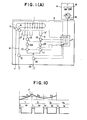
- Fig.1(A) is a schematic view for showing a basic technology of the present invention
- Fig.1(B) is a schematic view for showing more concretely than Fig.I(A)
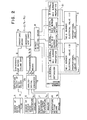
- Fig.2 is a block diagram for showing a how to use of No.1 invention
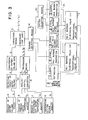
- Fig.3 is a block diagram for showing a how to use of No.2 invention
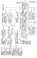
- Fig.4 is a block diagram for showing a how to use of No.3 invention
- Fig.5 is a graph for showing boundaries of each combustion zone
- Fig.6 is a pattern for showing a conbustion pattern of No.3 invention
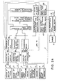
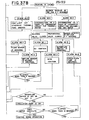
- FIG. 7 is a flow chart of No.3 invention for showing a proportional control of each burner
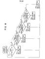
- Fig.8 is a flow chart for showing a pattern selection of No.3 invention
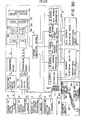
- Fig.9 is a flow chart of a program for showing a burner selecting treatment of No.3 invention
- Fig.10 is a graph for showing a relationship between a necessary heat load in the cycle of intermittent combustion and the ratio of on-time and off-time of burners in No.4 invention
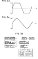
- Fig11 is a graph for showing an normal wave of AC source frequency in No.6 invention
- Fig.12 is a graph for showing an halfly rectified wave by means of SCR (silicon controlled rectifier) for example in No.6 invention
- FIG. 13 is a graph for showing a general pulse wave of a duty control in A type improvement invention
- Fig.14 is a graph for showing a voltage controlled wave in A type improvement invention
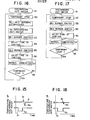
- Fig.15 is a graph for showing a conventional temperature chracteristic of a discharging hot-water in B type improvement invention
- Fig.16 is a flow chart for showing a conventional program involving delay-time between each burner switching in B type improvement invention
- Fig.17 is a flow chart for showing a improved program in B type improvement invention
- Fig.18 is a graph for showing an improved temperature characteristic of a discharging hot-water in B type improvement invention
- Fig.19 is a block diagram for showing a function of C type improvement invention
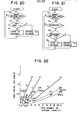
- Fig.20 is a flow chart for showing a conventional program of a blower control in C type improvement invention
- Fig.21 is a flow chart for showing an improvement program of a blower control in C type improvement invention
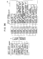
- Fig.22 is a graph for showing a
- Fig.1(A) and Fig.1(B) indicate an water heater body, (b) is a control panel, and the above water heater provides two units of burner against an unit of heat exchanger(1), saying No.1 burner(2) and No.2 burner(3), a fuel gas is fed into No.1 burner(2) and or No.2 burner(3) through a feeding gas pipe line(15), then made combustion, an water flowing into a feeding water pipe line(4) is heated in the heat exchanger(1).
- a feeding gas pipe line(15) is branched off in an halfway possition toward No.1 gas pipe line(15a) which connects to No.1 burner(2) and also No.2 gas pipe line(15b) which connects to No.2 burner(3) respectively, and a source electrical valve(16) is arranged in the upstream side of the above branch part.
- No.1 electrical valve(10) and No.1 proportional control valve(12) are arranged along the above No.1 gas pipe line(15a) and also No.2 electrical valve(11) and N o.2 porportion control valve(13) are arranged along the above No.2 gas pipe line(15b) in which these valves are arranged in order from the upstream respectively.
- No.1 burner(2) and No.2 burner(3) will be fed an amount of fuel gas in response to an opening ratio of No.1, No.2 proportional control valves(12)(13) when No.1, No.2 electrical valves(10)(11) are opened in advance under the state of a source electrical valve( 16 ) being opened initially, so that it will be able to control the heat capacity within a controllable range of No.1, No.2 proportional control valves(12)(13) by means of change an opening ratio and also a feeding gas-volume of No.1, No.2 proportional control valves(12)(13).
- the proportional control such control method of a heat capacity is refered to as the proportional control
- No.1, No.2 burner(2)(3) can make an intermittent combustion by means of repeating on-off action of No.1,No.2 electrical valves(10)(11), therefore, it will be able to control the heat capacity widely within a range between the highest heat capacity with a continuous combustion when both proportional control valves(12)(13) are kept with a constant fully opening and also both electrical valves(10)(11) respond with a longest on-time against off-time and in contrast the lowest heat capacity near to even zero value when its on-time of both electrical valves(10)(11) extremely shorten near to zero against its off-time.
- the intermittent combustion control such control method of a heat capacity is refered to as the intermittent combustion control
- No.1 burner(2) and No.2 burner(3) are composed to make a capacity of either one larger than another, and the lowest-limit combustion capacity of one burner having a large capacity is arranged to be smaller than
- No.1 burner(2) is composed of five pieces of burner nozzle so as to become No.4 combustion capacity in the lowest and No.15 combustion capacity in the highest
- No.2 burner(3) is composed of two pieces of burner nozzle so as to become No.1.6 combustion capacity in the lowest and No.6 combustion capacity in the highest.
- the water heater(a) will be able to control the heat capacity within a range between No.1.6 and No.6 of combustion capacity when uses No.2 burner (3) alone with a proportional control, and within a range between No.4 and No.15 of combustion capacity when uses No.1 burner(2) alone with a proportional control, and further, within a range between No.15 and No.21 of combustion capacity when uses both of No.1 burner(2) and No.2 burner(3) at the same time with a proportional control.
- the water heater(a) will be able to control the heat capacity within a range between No.0 and No.1.6 of combustion capacity when uses No.2 burner(3) alone, keeping No.2 proportional control valve(13) with a reasonable opening, being suited to No.3 of combustion capacity for example, repeating on-off action of No.2 electrical valve (11), then an intermittent combustion is done with the variation of on-off time ratio.
- this water heater(a) can control the heat capacity within a range between No.0 and No.21 of combustion capacity by means of a suitable combination of the burners and a switching of either one selectively, and furhter, a switching between a proportional control or an intermittent conbustion control of No.1, No.2 burner(2)(3).
- a sensor of water volume(5) is applicated in the upstream side of a heat exchanger(1), and a sensor of feeding water temperature(6) is arranged in where the former is of the upstream side, and further, a sensor of discharging hot-water temperature(7) is arranged in the downstream side of a heat exchanger(1) where is near to an exit of the heat exchanger (1).
- No.1 electrical valve(10), No.1 proportional control valve(12), No.2 electrical valve(11), No.2 proportional control valve(13), a sensor of water volume(5), a sensor of feeding water temperature(6) and a sensor of discharging hot-water temperature(7) are connected respectively with a microprocessor(17) electrically hereby, a sensor of water volume(5) will detect an water volume, saying it is an water flow rate shown by Q-value, which is flowed into a feeding water pipe line(4), and it will be transmitted into the microprocessor(17) as a detected data.
- the above water volume is regulated by a faucet and or other instrument of hot-water supply(27) [hereinafter, it is refered to as a faucet and the like(27)] in where is arranged in a termination of a feeding water pipe line(4).
- a sensor of feeding water temperature(6) will detect a feeding water temperature shown as Tc-value to be fed into a heat exchanger(1)
- a sensor of discharging hot-water temperature(7) will detect a temperature of discharging hot-water in which is showed by Th-value and discharged from a heat exchanger(1) hereby, these electrical signals will be transmitted into an analog-digital convertor as a voltage, and converted to such data of Tc-value and Th-value by means of said analog-digital convertor, and further, the above data will be transmitted into the microprocessor(17).
- a control panel(b) provides a power source switch(18) and a temperature setting means(8) hereby, Ts-value of set up temperature which is set up by the above temperature setting means(8) will be transmitted into an analog-digital convertor(19) which is showed in Fig.2 althogh the above Ts-value is merely a sort of voltage in this stage, and then it is converted to Ts-value data through the analog-digital convertor, and transmitted into themicroprocessor(17).
- the microprocessor(17) is housed in the water heater body(a), and owns itself an operations means(9) shown in Fig.1(B) and Fig.2 which caluculates a necessary heat load, and further, a burner selecting means(14) will determine for which burner is preferable and which control method is suitable in accordance with a necessary heat load which is calculated by said operations means(9).
- the operations means(9) acceptes Q-value of water volume in conversion of a pulse signal coming form a sensor of water volume(5), and further, acceptes each value of Ts, Tc, Th which are transmitted from a temperature setting means (8), a sensor of feeding water temperature(6) and a sensor of discharging hot-water temperature(7) through an analog-digital convertor(19), and then calculates a necessary heat load in accordance with the above data.
- a burner selecting means(14) dispatches a necessary signal into a burner controlling means(21) in order to drive No.1, No.2 electrical valves(2)(3) and No.1, No.2 proportional control valves(12)(13) in response to a necessary heat load indicated as F1-value which is calculated by the above operations means(9).
- each signal is divided into such five type of signal between [1]-signal and [5]-signal hereby,and firstly [1]-signal will close every valves of No.1, No.2 electrical valves(2)(3) and also No.1, No.2 proportional control valves (12)(13) and [2]-signal will close No.1 electrical valve(10) and No.1 proportional control valve(12),at the same time it makes No.2 electrical valve(11) to drive with on-off action intermittently in response to F1-value of a necessary heat load with a suitable cycle, furtherly it will open-No.2 proportional control valve(13) with an opening which is suited to No.3 combustion capacity, and [3]-signal will close No.1 electrical valve(10) and No.1 proportional control valve(12), and opens No.2 electrical valve(11), furtherly it makes No.2 proportional control valve(13) to drive with a proportional operation in response to F1-value of a necessary heat load, and [4]-signal will open No.
- a burner selecting means (14) will dispatch [1]-signal, and makes No.1, No.2 burners (2)(3) to extinguish, and further, when it is No. 0.1 ⁇ F1 ⁇ No.1.6, [2]-signal will be dispatched and it becomes an intermittent combustion of No.2 burner(3).
- the water heater(a) is under control of a proportional controlling combustion of No.1 burner(2).
- a burner selecting means(14) will dispatch [1]-signal, and makes No.1, No.2 burners(2)(3) to be under a fire extinguishing, when it is No. 0.1 ⁇ F1 ⁇ No.1.6, it dispatches [2]-signal and No.2 burner(3) becomes an intermittent combustion.
- No.1, No.2 burners(2)(3) are under a proportional control,when it is F1 ⁇ No. 0.1, a burner selecting means(14) dispatches [1]-signal and extinguishes both of No.1,No.2 burners, when it is No. 0.1 ⁇ F1 ⁇ No.1.6, it dispatches [2]-signal and convertes to an intermittent combustion of No.2 burner(3).
- a standard value for switching an intermittent combustion control and a proportional control by means of No.2 burner(3) is that; when it switches from an intermittent combustion control to a proportional control, it is No.2.5, when it switches from a proportional control to an intermittent combustion control, it becomes to No.1.6.
- a standard value for switching a proportional control of No.2 burner (3) and a proportional control of No.1 burner(2) is that; when it is switched from No.2 burner(3) to No.1 burner(2), No.6 becomes to the standard value but when it is switched from No.1 burner(2) to No.2 burner(3), No.4 becomes to the standard value.
- a standard value to switch a proportional control by No.1 burner(2) alone and a proportional control of both No.1, No.2 burners(2)(3) is as follows; When it is switched from No.1 burner(2) alone to both of No.1, No.2 burner(2)(3), No.10 becomes to the standard value, in contrast when it is switched from both of No.1, No.2 burner(2)(3) to No.1 burner(2) alone, No.8 becomes the standard value.
- a source electrical valve(16) of a feeding gas pipe line(15) turns on-off by an indication from the microprocessor(17) for safety's sake.
- an ignitor(82) is applicated around each burner (2)(3) so as to generate an ignition spark synchronizing with an opening of electrical valves(10)(11) corresponding to the burner(2)(3).
- this inventor has performed following an improvement upon the software as a partial improvement, that is, improved that No.2 electrical valve(11) of No.2 burner(3) is limitted to turn on-off when a necessary heat load is suited to a value less than the lowest limit combustion capacity of No.2 burner(3), saying assign an intermittent combustion control on an electrical valve(11) of No.2 burner(3), restrain the on-off frequency as much as possible excepting the above. ( Practical example of No.2 invention )
- the microprocessor(17) is housed in the water heater body(a), and has an operations means(9) to calculate F1-value of necessary heat load, a burner selecting means(14) to select a preferable burner in accordance with a necessary heat load which is calculated by said operations means(9), a control selecting means(20) to select a control method of heating capacity of said No.2 burner(3) when the above burner selecting means(14) selected No.2 burner(3) for example, and further, a burner controlling means(21) to generate a necessary power signal with an on-off action of electrical valves and an opening ratio of proportional valves into No.1, No.2 electrical valves(10)(11) and No.1, No.2 proportional control valves (12)(13) in response to the selection of the above each selecting means of a burner and a controlling method.
- An operations means(9) will start the action by means of detecting an water volume coming from a sensor of water volume(5) so as to take in an water volume Q-data in conversion of a pulse signal coming from a sensor of water volume(5), at the same time, take in such respective data of Ts, Tc, Th which are transmitted from a temperature setting means(8), a sensor of feeding water temperature(6) and a sensor of discharging hot-water temperature(7) hereby, calculates F1-value of a necessary heat load in accordance with these amount of data.
- a burner selecting means(14) will make four types of the selection relating to an using of burner in response to a necessary heat load operated by the above operations means (9).
- No.1 is a none using of both No.1, No.2 burners(2)(3) in which is selected when a necessary heat load is situated less than No.1 standard value.
- No.2 is an using of No.2 burner(3) in which is selected when a necessary heat load is situated within a range between No.1 standard value and No.2 standard value.
- No.3 is an using of No.1 burner(2) in which is selected when a necessary heat load is situated within a range between No.2 standard value and No.3 standard value.
- No.4 is an using of both No.1, No.2 burner(2)(3) with a combination in which is selected when a necessary heat load exceeds No.3 standard value.
- No.1 satndard value is at No.0.1 combustion capacity
- No.2 is at No.6 which is situated to the highest combustion capacity of No.2 burner(3)
- No.3 standard value is at No.15 which is situated to the highest combustion capacity of No.1 burner(2).
- a control selecting means(20) will be limitted to do the action when the above burner selecting means(14) decided to the selection of No.2, saying it is an using of No.2 burner(3).
- a selective control method will be either of an intermittent combustion control or a proportional control any way, therefore, the control selecting means(20) will select an intermittent combustion control when the necessary heat load is situated less than No.4 standard value in which is arranged between No.1 standard value and No.2 standard value,also will select a proportional control when it exceeds the above No.4 standard value respectively.
- No.4 standard value will be arranged at No.16 combustion capacity which is situated to the lowest limit combustion capacity of No.2 burner(3) for example.
- a burner controlling means(21) in which generates a power signal to drive an electrical valve with an on-off action and an opening power signal to a proportional valve will dispatch five types of signal selectively in response to the above burner selecting means(14) and a control selecting means(20).
- the above five types of signal are basically seperated to following mode of an intermittent combustion controlling signal of No.2 burner(3), a proportional control signal of No.2 burner(3), a proportional control signal of No.1 burner(1), a proportional control signal of both of No.1, No.2 burners(2)(3) and a fire extinguishing signal for both burners(2)(3).
- a signal of a fire extinguishing (it is refered to as an extinguish signal hereunder ) will be dispatched when the burner selecting means(14) decided to a none-using of No.1, No.2 burners(2)(3), and then closes such every valves of No.1, No.2 electrical valves(10)(11) and No.1, No.2 proportional control valves(12)(13).
- An intermittent combustion signal of No.2 burner(3) will be dispatched when the burner selecting means(14) decided to an using of No.2 burner(3), beside, a control selecting means(20) decided to an intermittent combustion control hereby, such being the case, No.1 electrical valve (10) and No.1 proportional control valve(12) will be closed, No.2 electrical valve(12) will be turned on-off intermittently in response to a cycle and a time-ratio of on-off time, at the same time, also No.2 proportional control valve(13) will be opened with a predetermined opening, for example it is an opening suited to No.3 combustion capacity.
- No.2 burner(3) will burn intermittently with a cycle and a time-ratio of an on-off time in response to a necessary heat load.
- a proportional combustion signal(h) of No.2 burner(3) will be dispatched when a burner selecting means(14) selected No.2 burner(3) and also a control selecting means(20) selected a proportional control, and then No.1 electrical valve(10), No.1 proportional control valve(12) and No.2 electrical valve (11) are opened respectively at the same time, beside, No.2 proportional control valve(13) is operated with a proportional action in response to a necessary heat load.
- No.2 burner(3) will make a continuous combustion with a suitable amount of a fuel gas in response to a necessary heat load.
- a proportional combustion signal(J) of No.1 burner(2) will be dispatched when the burner selecting means(14) selected an using of No.1 burner(2), and No.1 electrical valve(10) is opened, No.1 proportional control valve(12) is operated in response to a necessary heat load, and also No.2 electrical valve(11) and No.2 proportional control valve(13) are opened.
- a proportional combustion signal of No.1, No.2 burners(h)(J) will be dispatched when the burner selecting means(14) selected a common using of NO.1, No.2 burners(2)(3), and NO.1, No.2 electrical valves(10)(11) are opened and both of No.1, No.2 proportional control valves (12)(13) are operated in response to a necessary heat load. Therefore, when this signal is dispatched, No.1, No.2 burners(2)(3) will be made a continuous combustion commonly with a suitable amount of a fuel gas in response to a necessary heat load.
- a standard value of a burner selection and a control selection are not always needed to be limitted for the above refered standard values,it is rather allowed to determine the standard value owing to circumstances of control, so that it is possible to set up different standard values eachother between a case of a necessary heat load varying to an increasing direction and a case of it varying to a decreasing direction.
- No.2 invention is under a state of an operation, and is discharging a hot-water with a comparatively lower temperature. So that No.2 burner is keeping an on-off combustion with a slow cycle. In this time, suddenly change the set up temperature into a high temperature side, that is, a necessary heat load is considered to settle finally within a region of No.1 burner's single combustion with a proportional operation. However, a some state of confusion will occure during a switch of the burner.
- Such miscasting confusion of each burner becomes, as a result, to increase a damage-ratio of each apparatuses of operational part, for example, to increase an actional frequency of an electrical valve and the like.
- the selection of burner is made by means of a necessary heat load which is calculated with a feedforward of a set up temperature, an water feeding temperature and an waterflow rate, however, even if a hot-water feeding temperature is unable to rise up to the set up temperature in a initial stage of the combustion, still holds a partial charge of a predetermined burner's combustion, furtherly if there is a large amount return of a feedback value, still it maintains a proper combustion including an amount of a feedback within a range of the highest combustion capacity of the burner in charge, therefore such improvement was performed into the software so as to be able to prevent the aforesaid burner miscast. Therefore, this improvement is refered to as No.3 invention hereunder.
- a microprocessor(17) is composed to provide following six mode of a processing means, that is, [1] a detecting means of a combustion state at moment(28) to detect an operated buner at moment and a combustion state at moment, [2] a selecting means of a combustion pattern(29) to select a predetermined combustion pattern from predetermined pural patterns according to a state of an operated burner and its combustion at moment( is it under a fire extinguishing, under an intermittent combustion or under a proportional combustion?), [3] an operations means of a feedforward value(30) to calculate a necessary heat load (it is refered to as a feedforward necessary heat load hereunder) in accordance with a hot-water discharging temperature Th-value, a set up temperature Ts -value and a proprotional gain, [5] a burner selecting means(14) to select and determine a preferable burner and its combustion method from a selected pattern of a combustion of
- the above combustion patterns are arranged preliminarily with following five pieces of pattern from No.1 pattern to No.5 pattern in accordance with a operated burner at moment and its combustion state. Also these five pieces of pattern from No.1 to No.5 are arranged so as to meet with each value which are converted from each boundary of f1, f 2 and f 3 of each combustion zone of A, B, C, and D in response to an increasing direction or a decreasing direction of the heat load.
- a predetermined combustion pattern is selected from five pieces of combustion pattern shown in Fig.6 in response to a presently operated burner and its combustion state.
- No.1 pattern is selected when it is under a fire extinguishing
- No.2 pattern is selected when No.2 burner is under an intermittent combustion
- No.3 pattern is selected when No.2 burner is under a proprotional combustion
- No.4 pattern is selected when No.1 burner is under a proportional combustion
- No.5 pattern is selected for other case excepting the above four cases.
- Step P5 an operations means of a feedforward value (30) will determine a preferable burner and its combustion method in a combustion zone which is suited to F i -value of a feedforward necessary heat load which is calculated by the above operations means of a feedforward value(30).
- No.2 burner is operated with an intermittent combustion when F 1 -value of a feedforward necessary heat load is suited to a range(A-zone) of F 1 ⁇ f 1
- No.2 burner is operated with a proportional combustion when F 1 -value is suited to a range (B-zone) of f 1 ⁇ F 1 ⁇ f 2
- No.1 burner is operated when F i -value is suited to a range(C-zone) of f 2 ⁇ F 1 ⁇ f 3
- No.1, No.2 burners are operated with a proportional combustion at the same time when F 1 -value is suited to a range(D-zone) excepting the above A, B and C zone and the
- an enough feedback value is given, accordingly, it can discharge a hot-water with a required set up temperature immediately, and also a responding character is improved against a set up temperature having a large-different temperature.
- a minus-value of a feedback is added into a feedback necessary heat load, therefore, it can control with a combustion of an improved responding character.
- each combustion pattern as shown in Fig.6, are arranged so as to be able to improve a further capability of a hot-water discharge in each combustion zone of A, B, C and D. That is, in No.4 pattern, aboundary between a proportional combustion zone(D-zone) of No.1, No.2 burner (2)(3) and a proportional combustion zone(C-zone) of No.1 burner(2) are arranged at No.10 combustion capacity, however, these boundary of each pattern of No.1, No.2 No.3 and No.5 are arranged at No.8 which is decreased from No.10 of the former.
- No.9 combustion capacity was suited to a combustion zone(C-zone) of No.1 burner(2) alone, so that it might make a combustion within a range of No.1 burner(2) capability between No.4 and No.15 combustion capacity.
- No.9 combustion capacity of a feedforward is of F 1
- its final heat load is of F for example
- no.5 pattern as shown in Fig.6 a boundary between C-zone and B-zone is arranged at No.6 combustion capacity in which is drawn up from No.4 combustion capacity comparing to No.4 pattern. Therefore, during a combustion of No.1, No.2 burners(2)(3), when a requirement of a feedback F 1 -value is drew down to No.5 combustion capacity, it is transited to B-zone from D-zone immediately and it is controlled so as to be driven a large amount of a minus-feedback.
- This No.4 invention has two major meaning.
- One is a fundamental invention featuring these group of invention so far, that is, it gave a solusion of a combinational combustion of plural gas burners including an intermittent combustion under control of a microcomputer.
- An other meaning is that, reviewing the stream of improved technologies from a field of a commercialization, it is understandable that a merchandise flows toward a making into high-class and deluxe as a merchandise in each time elapsed.
- the combustion system is diverted No.1 burner of the proto type to the purpose, and also the control method is diverted an intermittent combustion method peculiar to No.2 burner on the proto type.
- a form of a heat source of an instantaneous gas water heater is decided to on-off control by an unit of a burner.
- a necessary heat which is operated with a time-ratio between a on-time and a off-time within a cycle of an intermittent combustion peculiar to No.2 burner of the proto type, and also a necessary heat load which is to be a standard value of the control will be calculated by a feedforward detected in due course by means of a setting temperature, an water feeding temperature, a hot-water discharging temperature and an waterflow rate as well as aforesaid proto type, however, as shown in the aforesaid control of the proto type, an instantaneous gas water heater has various unstable factor ot control generally tnereoy, accordingly, how does it make to stabilize, this is a serious question of the simplified type.
- an operations means(9) of the control system will calculate an average amount of a heat capacity consumed during the one round immediately and memorized it in due cource.
- a combustion of a burner becomes to be controlled with a pulse-time which is determined by a time-ratio between on-time and off-time in accordance with an average amount of a heat capacity memorized already. That is, this is a technology to be obtainable an amount of hot-water discharge by means of control of on-off combustion cycle.
- (a) is an water heater body, and it is composed to make a combustion of a fuel gas fed through a feeding gas pipe line(15) into No.1 burner(2),to flow a feeding water through a feeding water pipe line(4) in to a heat exchanger(1) thereby, to be heated up and discharged into a faucet and the like(27) through a hot-water discharging pipe line(34).
- a source electrical valve(16), No.1 electrical valve (10) and a gas regulator(22) are arranged along a feeding gas pipe line(15) in the upstream side of the former.
- a hot-water discharging pipe line(34) is branched to a return-pipe line(32) in a halfway, exactly it is branched from near a faucet and the like(27), however, in view of circumstances, it will be explained in case of the later.
- a circulation pump(35) will suck an amount of a hot-water flowing within a hot-water discharging pipe line (34) into a return-pipe line(32) basically, and a small capacity of a circulation pump which is suited to a flow rate of two litre per minute will be adoptable so as to do not prevent a main flow of a hot-water discharge into a faucet and the like(27).
- No.1 electrical valve(10), a sensor of water volume(5) of a feeding water pipe line(4), a sensor of a feeding water temperature(6), a sensor of a hot-water discharging temperature(7) and a circulation pump(35) of a return-pipe line(32) are connected respectively with an operations means(9) electrically, a sensor of water volume (5) will dispatch a signal(c) in detect of an water flow rate flowing within a feeding water pipe line(4), and a sensor of a feeding water temperature(6) will dispatch a signal(d) in detect of an water feeding temperature flowing into a heat exchnger(1), furtherly, a sensor of a discharging hot-water temperature(7) will dispatch a signal(e) in detect of a hot-water discharging temperature coming from a heat exchanger(1), so that these signal of (c), (d) and (e) will be sent to the operations means(9) respectively.
- the operations means(9) is housed within an water heater body or a control panel(b), and according to the action of a switch-on of a power source switch(8), it will dispatch a signal(L)into a circulation pump(3) for operating it, at the same time, accepting these signal of (c), (d) and (d), the operations means(9) will calculate in comparision of a balance value between these each value of an water flow rate, an water flow temperature, a hot-water discharging temperature and, on the other hand, a set up temperature by means of a temperature setting means(8) thereby, it calculates a necessary heat load F-value as shown in Fig10, and furhter, calculates an average amount of a necessary heat load F-value in the intermittent combustion cycle T-value as the total amount of a burner's on-time t 1 -value and a burner's off-time t 2 -value thereby, the operations means(9) will send a pulse-signal(i) with a pulse-span in compliance with the average amount
- No.1 elctrical valve(10) accepts a pulse-signal (i)
- its valve is opened during going on of on-time t 1 , and it is closed during off-time t 2 in accordance with a length and a span of the pulse-signal, and it is operated with a determined time-ratio.
- No.1 burner(2) will repeat the combustion intermittently with a length and a span of a pulse-signal (i), in other word, it is operated with a time-ratio between on-time t 1 and off-time t 2 determined by an average amount of a necessary heat load F in the intermittent combustion cycle just before.
- a sensor of a hot-water discharging temperature(7) detects that a feeding water temperature does not reach to a set up temperature for example, then an operations means(9) will begin to calculate a necessary heat load F, at the same time, a circulation pump(35) will begin the rotation, and No.1 electrical valve(10) will turn on-off action, accordingly, No.1 burner(2) will begin the combustion.
- an amount of water which is contented within a pipe line system will be circulated through a feeding water pipe line(4), a heat exchanger(l), a hot-water discharging pipe line(34), and returned back into a feeding water pipe line(4) where is in the upstream of a sensor of water volume(5) along the pipe line by means of the circulation pump(35) operation, furtherly it is heated up when it is transitted in a heat exchanger(1).
- an intermittent combustion of No.1 burner(2) is controlled by an operations means(9) with a time-ratio between on-time t 1 and off-time t 2 which are determined by an average amount of a necessary heat load F, so that a circulating water is heated up until reaches to a set up temperature, and kept the temperature continuously.
- a valve of a faucet and the like(27) is opened, an amount of a hot-water contented within these pipe lines being heated up already will be supplied into a faucet and the like(27) thereby, an amount of a feeding water which is fed newly from a feeding water pipe line(4) will be heated up to a set up temperature, and supplied into a faucet and the like(27).
- a circulation pump(35) continues the operation, however, it does not prevent _ to supply an enough amount of a hot-water into a faucet and the like(27) due to a small capacity type of a pump to suck a small amount of a hot-water from a hot-water discharging pipe line(34) into a return-pipe line(32).
- this inventor offered a technology to control a combustion if an intermittent combustion mehtod by means of a single burner.
- the inventor paid attention to perform a keeping-warm of a hot-water with a force circulation of a circulation pump within a circulational by-pass pipe line provided.
- this inventor is going to offer a following means, that is, it is a technology of that no more use of No.1 burner for the heat source of a keeping-warm operation as like a prior case of No.4 invention, and newly provides an electrical heater along a circulating by-pass pipe line for a keeping-warm purpose only instead of No.1 burner thereby, and it is controlled suitably by a control system.
- No.5 invention Practical example of No.5 invention
- composition of a hardware section that is, these composing elements and each gist of an operation with following each apparatuses of; a feeding water and a discharging hot-water pipe line systems, a fuel gas pipe line system, a heat exchanger and a burner systems, a proportional gas valve to operate the above each apparatuses; an electrical valve with its controlling apparatuses are quite similar to aforesaid No.1 invention and or No.4 invention.
- a practical characteristic of this No.5 invention relates to offer to a technology of arranging an electrical heater(36) along to a return pipe line(32) which is shown in Fig.1 as a heat-source of a keeping-warm of a recirculating hot-water.
- An electrical heater(36) is insertingly connected with an inlet port which is provided along to a return pipe line(32).
- the above electrical heater(36) will be used in which it can generate a more larger heating capacvity than an amount of a heat-loss radiating from a total system of a pipe line in a normal setting state.
- circulation pump(35) and the electrical heater are connected with a microprocessor(17) so as to be controlled by the microprocessor(17).
- the microprocessor(17) is composed to be operated by a switch-on of a power source switch(18) initially, and to calculate a different value between a set up temperature and a recirculating hot-water temperature(detected by a sensor of a hot-water discharging temperature), and also to calculate a necessary heat capacity to heat up the circulating hot-water up to a set up temperature, and further, to calculate an other necessary heat capacity to make a keepng-warm with a set up temperature so as to vary a voltage of the electrical heater(36) after the water heated up.
- the electrical heater(36) is driven with a large amount of voltage in response to the above, and in contrast, a smaller amount of a necessary heat capacity comes, then it is driven by a smaller voltage.
- a heating capacity is varable, and makes to heat up an amount of a recirculating hot-water continuously with a suitable heat capacity meeting with a voltage given by a power output section of a microprocessor (17), and also maintains a keeping-warm operation.
- a microprocessor(17) was composed to vary the voltage of the electrical heater (36) in response to a necessary heat capacity which was calculated when the circulating hot-water in a heating process and also a keeping-warm process, however, however, it is allowed to be composed to make the electrical heater(36) to turn on-off intermittently so as to vary a time-ratio between on-time and off-time in response to a necessary heat load.
- the technology to cover a keeping-warm of a recirculating hot-water by means of an electrical heater instead of a gas heat source of No.1 burner during a none-discharging hot-water in the above No.5 invention was certainly beneficial for the accident prevention of a user involving a scald and the like during a hot-water discharge.
- an electrical heater is an energy-waisting type means as a heater. Accordingly, in consideration of a social responsibility of the inventor as one of such a heating equipment manufacturer, and also the operation-cost consciousness for the user of the water heater, this inventor is in a place to review the keeping-warm method in use of an electrical heater.
- No.4 invention it was composed to recirculate a pipe line contained water so as to keep a warm with a burner excepting a hot-water discharging period.
- the controllable lowest limit of combustion capacity is limitted within a range of 1/4 or 1/5 of the highest limit of combustion capacity due to a reason of a burner structure, so that it remained a question even if a circulative flow line is provided so as to heat up the circulating water.
- a circulation pump flow rate is of 2 litre per minute
- a keeping-warm set up temperature is of 60 °C
- a circulating hot-water temperature is of 55 °C
- a combustion capacity of a burner is of No.4 combustion capacity(generatable 100 Kcal per minute).
- the burner is unable to be ignited unless a different temperature(At) between a keeping-warm set up temperature and a circulating hot-water temperature being fairly larger, and further, once time ignited, a rising temperature is bigger and shows a large huntting of a hot-water discharging temperature.
- the circulating water has such a problem of that a large amount of the water flow will release a large amount of radiational heat-loss from the whole surface of the piping system and contrarily a smaller amount of the water flow will make difficult to control in the keeping-warm operation.
- a technically adoptable means by the invention for resolving the above problem is that an halfway part of a hot-water discharging pipe line and a feeding water pipe line are jointed each other with a return pipe line having a circulation pump along to the line thereby, an amount of an water is forcedly circulated within a loop line which consists of a feeding water pipe line, a heat exchanger, a hot-water discharging pipe line and a return pipe line during a none-using period of a hot-water discharge, and further, a burner is operated with an intermittent combustion, it calculates a necessary heat capacity to be needed for maintaining a keeping-warm of the circulating water with a predetermined set up temperature in accordance with these elements of a circulating water flow rate, a circulating water temperature and a predetermined set up temperature, the set up temperature in which are detected respectively by means of a sensor of water volume and a sensor of a feeding water temperature, and furhter, a time-ratio of on-time of the above burner is controlled, and the circulation pump
- the composition of the hardware section that is, these composing elements and the gist of operartion with following each apparatuses of a feeding water pipe line and a discharging hot-water pipe line, a fuel gas feeding pipe line, a heat exchanger and a burner system, a proportional control valve to control the above heating apparatuses, an electrical valve with its controlling apparatuses are quite similar to aforesaid No.1 invention, No.2 invention and No.4 invention, and further, a return pipe line(32) is provided along to a hot-water discharging pipe line(4), and also a circulation pump(35) is applicated along to said pipe line(32) thereby, these respective apparatuses will compose a structural characteristic of the hardware section in this invention.
- the microprocessor (17) is composed to control electrically the circulation pump(35) with a phase control in accordance with a predetermined target flow rate and also an actual flow rate which is detected by a sensor of water volume(5) in acceptance with a signal from a sensor of water vclume(5).
- phase control is that an oscilloscopic waves of a commercial A.C.(alternating current) frequency as shown in Fig.11 is partially cut off as shown in Fig.12 in use of a SCR(silicon controlled rectifier) and the like for example, so that an motor revolusion of the circulation pump is controlled with a variation of a cutting off ratio.
- the above target flow rate is arranged in the most suitable flow rate so as to be preventable a large quantity of a heat-loss caused by a too much flow rate within the loop pipe line system, contrarily too small flow rate may produce bad results in the control.
- the above target flow rate is preferable to set up at around 2 litre per minute generally.
- the circulation pump(35) is able to operate continuously regardless of a hot-water discharging from a faucet and the like(27) or not during the water heater body(a) is under operation.
- the above circulation pump(35) is also allowed to be operated limittedly during no discharge of an hot-water from the faucet and the like(27).
- No.1 electrical valve(10) will be operated with on-off action so as to make an intermittent combustion of No.1 burner(2).
- an water contained within the whole pipe line system is flowed forcedly by the circulation pump(35) from a feeding water pipe line(4) to a heat exchanger(1), a hot-water discharging pipe line(34), and flowed back into the feeding water pipe line(4) where being in the upstream position near to a sensor of water volume(5), and then warmed up during passing through the heat exchanger(1).
- the above flow rate of the circulation water is controlled within a range of a target flow rate with a phase control operation in the circulation pump(35) in accordance with the target flow rate and also an actual flow rate which are calculated by means of a microprocessor(17) through a detection of a sensor of water volume(5), for example, the controllable target flow rate is 2 litre per minute.
- the above circulation pump is composed to rotate with a none-stop operation during discharge of a hot-water, and flows back 2 litre per minute of a hot-water into the pump through a by-pass pipe line.
- the above circulation pump is composed to be operated even in a discharging period of a hot-water though it is proper that it is operated during a keeping-warm period, it takes 2 litre perminute of a hot-water out of a discharging water from the heat exchanger, and flows back it into the circulation pump through a return pipe line.
- this flow back way of the recirculating hot-water during discharge of hot-water may be utterly meaningless but also it constantly knocks 2 litre per minute of a hot-water off the sum before discharging the hot-water.
- This none-stop operation method of the circulation pump may not only spoil of the mechnical life of the circulation pump itself but also waiste of the operational power, so that it brings such an economically illogical disadvantage to the general user of the water heater.
- this inventor will offer to conduct following improved technology into aforesaid software of A-type improved invention.
- Such a means to make the rotation of the circulation pump to stop during discharge of the hot-water from a faucet and the like(27) may be variously considerable in a commonsense.
- it is considerable to control the circulation pump in accordance with a variation of an water pressure or a variation of an water flow rate for example, there may be a way to catch an water-pressure variation mechanically by means of a diaphragm valve and the like during the discharge of the hot-water, otherwise, a way to catch a sudden variation of an water flow rate during the discharge of the hot-water in the electronics by means of a sensor of water volume(5) and the like.
- the microprocessor(17) is composed so as to calculate a necessary heat load in response to a predetermined elements of an water flow rate detected by a sensor of water volume(5), a feeding water temperature detected by a sensor of a feeding water temperature(6) a set up temperature established by a setting temperature section(8), a hot-water discharging temperature detected by a sensor of hot-water discharging temperature(7), a heat efficiency of a heat exchanger(lh and a proportional gain and the like thereby, and furhter No.1 electrical valve(10) is turned on-off with an interval and a time-ratio in response to a calculated necessary heat load, furtherly, an operation of a circulation pump(35) is stoped once time temporarily.
- a valve of a faucet and the like(27) is opened thereby, firstly an amount of hot-water which is made hot already containing a set up temperature within a pipe line system will be supplied into a faucet and the like(27), nextly an water in which is fed newly from a feeding water pipe line (4) will be warmed up to a set up temperature, and discharged.
- a hot-water discharging flow rate becomes larger than a circulating water flow rate naturally, that is, it is larger than 2 litre per minute, and also also these flow rate of flowing within a feeding water pipe line(4), a heat exchnger(1) and a hot-water discharging pipe line(34) will become larger, in response to the above, an amount of necessary heat load will be calculated automatically by means of the microprocessor(17), and in response to the above calculated necessary heat load, No.1 burner(2) will be controlled in the most suitable condition with an intermittent combustion, therefore, a continuous discharge of a hot-water containing a set up temperature will be performed certainly.
- the above calculated necessary heat load will exceed largely the highest heat capacity in which is needed for a keeping-warm operation, also it becomes to exceed aforesaid predetermined value, for example, it is 150 Kcal per minute, so that the microprocessor(17) will stop the operation of the circulation pump(35).
- a necessary heat load calculated by a microprocessor(17) will be decreased automatically in response to the above stop, and it becomes to a smaller value less than aforesaid predetermined value, that is, 150 Kcal per minute.
- the circulation pump(35) will start with the operation again, and a hot-water contained within the pipe line system is flowed circulatingly again, and awaits for next using of the hot-water by the faucet and the like(27).
- this inventor is going to offer newly a control technology in an waterflow-rate detecting basis as follows;
- the meaning of the above waterflow-rate detecting basis will be that, in detection of the sensor of water flow(37), the sensor(37) will detect a variation value of water flow rate which is flowed forcedly within a feeding water pipe line(4) during a hot-water discharge and also none-discharge thereby, through these selection and a indication for a necessary heat source and a combustion pattern, finally the most suitable heating will be performed upon the circulating water.
- the habitat factor of the water temperature detection is largely affected by a geographical condition and or a seasonal condition, so that it is easily imaginable that the amplifying span for a controlling object will be widen as much as possible in order to respond for a widely spanned variation and or a suddenly changeable disturbance.
- the composition and its each operational gist of the hardware consisting apparatuses of both pipe lines of a feeding water and a hot-water discharge, furtherly a fuel gas feeding pipe line, a heat exchanger and a burner system, and a proportional gas valve to control of the above, and a electrical valve and its relating control system are quite similar with aforesaid series invention of No.1 invention, No.2 invention, No.5 invention, A-type improved invention and No.6 invention.
- the microprocessor(17) is connected electrically with these apparatuses of electrical valves(11), (10), proportional valves(13), (12), a sensor of hot-water discharging temperature(7), a circulation pump(35), a sensor of water volume(5), a sensor of feeding water temperature(6) respectively, and the microprocessro(17) will dispatch a signal(L) to said circulation pump(35) to drive it, on the other hand, the microprocessor(17) will accept these sensing signal(e), (c) and (d) from the above each sensors of (7), (5) and (6) thereby, calculates a necessary heat load for keeping a warm of a circulating water during a discharge - and a none-discharge of the hot-water, and further, according to a volume-variation of a necessary heat load, it selects a smaller capacity type No.2 burner(3) and or a larger capacity type No.1 burner(2).
- the microprocessor (17) will dispatch, in case of the smaller capacity type No.2 burner(3) being selected once time, a pulse-signal(g) into No.2 electrical valve(11) responding to a necessary combustion capacity when the necessary heat load is less than a predetermined combustion capacity.
- the pulse-interval is arranged each other differently with two kinds for a discharge of hot-water and a none-discharge of hot-water respectively, saying the former interval is short and the later is longer.
- the valve(11) is operated in on-off action respectively in compliance with the length of the pulse-interval, and a fuel gas is fed into No.2 burner(3) intermittently. Therefore, a smaller capacity type No.2 burner(3) is controlled with different cycles, for example, 5 second time-length is performed for a hot-water discharge and 30 second time-length is performed for a none-discharge of hot-water thereby, and so that the above No.2 burner(3) is operated with on-off action repeatedly so as to warm up the circulation water through the heat exchanger(1).
- on-signal(g)(to open) is dispatched from the microprocessor(17) into No.2 electrical valve(11) when the necessary heat load is more than a predetermined combustion capacity
- a signal(h) is also dispatched into No.2 proportional valve(13) in response to each different value of necessary heat load for both cases of a discharge of hot-water and a none-discharge of it.
- No.2 proportional valve(13) will feed a fuel gas into No.2 burner(3) continuously in response to the necessary heat load in correspondence with the above each case.
- a smaller capacity type No.2 burner(3) is operated continuously with a necessary combustion capacity for a discharge of hot-water, and the heat exchanger(1) is heated up by the burner(3).
- on-signal(i)(to open) is dispatched into No.1 electrical valve(10) so as to heat up the heat exchanger(1) by means of the above No.1 burner(2).
- a sensor of waterflow rate(37) which detects the waterflow rate of discharging hot-water and also a state of none-discharge of hot-water will be applicated in the upstream side of a joint section of a return pipe line(32) branched from a feeding water pipe line(4) thereby, the sensor of waterflow rate(37) will start the detection in response to an waterflow movement into the heat exchanger(1) from the feeding water pipe line(4) and the water source during the discharge of a hot-water so as to dispatch the signal(M) into the microprocessor(17). That is, the microprocessor(17) is basically programed to determine such each state of dischaging a hot-water and stopping it in accordance with yes or no of signal(M) dispatched from the sensor of waterflow rate(37).
- a microprocessor (17) will calculate a necessary heat load in response to these respective signal of (e), (c) and (d) which are detected by means of these each sensor of a hot-water discharging tempertature(7), a sensor of water volume(5) and a sensor of a feeding water temperature(6) thereby, a smaller capacity type No.2 burner(3) will be selected when the necessary heat load is less than a predetermined combustion capacity, and furhter, a larger capacity type No.1 burner(2) will be selected when the necessary heat load is more than a predetermined combustion capcity.
- an waterflow movement toward a heat exchanger(1) is detected by a sensor of waterflow(37), and the microprocessor(17) accepts the signal(M) dispatched from the above sensor of waterflow (37), and distinguishes the state of hot-water discharge, and regulates an amount of fuel gas supply into each No.1, No.2 burners(2), (3) selected respectively.
- No.2 burner will be operated with the cycle in response to the state of a hot-water discharge when the necessary heat load is less than a predetermined combustion capacity, and a heated up water within the heat exchanger(1) to a predetermined temperature will be supplied into the faucet and the like(27).
- the burner(3) will be operated continuously when the necessary heat load is more than a predetermined combustion capacity in response to the necessary heat load so as to warm up the heat exchanger(1) to maintain the hot-water in a predetermined temperature.
- No.1 bruer(2) will be operated continuously in response to the necessary heat load calculated in accordance with a detecting signal from these sensors of (7), (5) and (6) thereby, a hot-water being heated up within a heat exchanger(1) will be supplied into a faucet and the like(27).
- a sensor of waterflow rate (37a) is arranged along to a return pipe line(32), and the sensor(37a) is composed to make its action in response to sense an waterflow movement within a return pipe line(32) during a none-discharge of hot-water.
- a circulative waterflow of the return pipe line(32) is sensed by the sensor of waterflow rate(37a) within the return pipe line(32) a micriprocessor(17) will accept a signal(Ma) from a sensor
- No.7 invention the inventor offered such a technology to perform an intermittent combustion stably by a small capacity type No.2 burner(3) in accordance with an waterflow detection during a none-discharge of hot-water contained in the water heater.
- a small capacity type No.2 burner(3) in accordance with an waterflow detection during a none-discharge of hot-water contained in the water heater.
- the prior technology offered once time when it is switched from none-discharge of hot-water to reopen of discharge, an amount of hot-water warmed and faithfully maintained in a predetermined set up temperature will be discharged from a faucet and the like, accordingly the danger of jeopardizing the user to a scold and the like was certainly avoided.
- the axis of abscissas shows a time
- (A) is a hot-water discharging volume
- (B) shows a hot-water discharging temperature.
- A is a hot-water discharging volume
- B shows a hot-water discharging temperature.
- a hot-water discharging temperature(B) shows a sharp rise immediately once time(Bi), nextly it shows a sharp drop immediately to (B 2 ), and it restores to (B) again in due cource of time.
- No.1 burner(2) is ignited again(53), through a igniting time(54), during that time, the control section will calculate in getting of informations, or will distinguish to dispatch a necessary signal of operation, in these ways, nextly No.2 burner(3) is ignited again(55). Furtherly, a slow igniting time squeezes into there again between the above switching, and then it scarcely enters into saying the state of a normalized combustion at last. That is, according to the five kinds seperated operational circuit-signal which are dispatched from the control system judgement section of the proto type water heater of the invention, No.1, No.2 burners(2),(3) will be operated with each combination of the combustion, and then follows up to the set up temperature.
- this inventor intended to perform an improvement into the software so as to take the slow igniting time at the same time for No.1 burner(2) of (52) and also for No.2 bruner(3) of (53).
- B-type improved invention is similar to these compositions and operational gists of No.1 invention as the basic invention, No.5 invention, A-type improved invention, No.6 invention and No.7 invention in which are composed by these systems and an apparatus of a feeding water pipe line a dischrging hot-water pipe line channel, a fuel gas feeding pipe line channel, a burner system and a heat exchanger channel and the like.
- the main object of the B-type improved invention will be to perform an improvement upon the software as follows;
- a valve of a faucet and the like(27) is opened so as to discharge a hot-water(51), and nextly the valve of the faucet and the like(27) is closed so as to stop the discharge of hot-water temporarily(52).
- the above temporary stop(52) is meant that it is closed to the valve of the faucet and the like(27) so as to stop the discharge of hot-water, and No.1, No.2 burners(2),(3) are stoped respectively, after that, the valve of the faucet and the like(27) will be opened again in due cource of time.
- No.1 electrical valve(10) is opened so as to ignite No.1 bruner(2) (53), and No.2 electrical valve(11) is opened so as to ignite No.2 burner(3) (55).
- F 2 is a rectified heat load thereby, now the coefficient is of ⁇ for example, this equation, saying F 2 - d x (Ts-Th) x Qh is formulated.
- This type of burner is composed that a pressurized premixed fuel gas is injected blowingly into a venturi tube opened in the direction of the downstream from the gas jetting nozzle thereby, a partial amount of the primary air will be sucked into the venturi according to the venturi theory, and an injected fuel gas and a sucked-in the air will be mixed in there with an air-mixing ratio of 30% to 80% of a partial air from the theoretical rate of the combustion air, and a totally mixed gas is fed into the combustion nozzle so as to perform a flame ignaited by a predetermined ignition apparatus around the nozzle, and further, gaining a necessary secondary air for combustion from the environment, and it becomes to obtain a typically premixtured type flame, in other word, it is so called as a Bunsen type flame in general.
- the main object of C-type improved invention is to perform a drive-control of a forced air blower through blower operation circuit(N) by the microprocessor(17) in which provides a forced air blower(38) in the upstream direction of a combustion air intake port of the burner.
- the microprocessor(17) provides an waterflow data conversion means(24) to gain an waterflow rate(Q) from an waterflow signal of an waterflow rate detecting circuit(25), and a temperature data transmission means(48) to gain a feeding water temperature(Tc) and a hot-water discharging temperature(Th) which are transmitted through an analog-digital converting circuit(19) and an operations means of a feeding water temperature averaged value (26) to calculate an averaged value(Th) of a hot-water discharging temperature(Th) within a predetermined time.
- the instantaneous gas water heater is controlled in accordance with a these operational gist shown in the flow chart of Fig.20.
- this flow chart shows of the case of controlling an intermittent combustion of a smaller capacity type No.2 burner(3). That is, in Step(P 1 ), it is distinguished for [yes] or [no] of a keeping-warm operation, and in case of responding [no] of a denial, it continuously sounds the [yes] or [no] until detects a signal of a keeping-warm operation, and in case of responding [yes] of proceeding to a keeping-warm operation, it will step up to Step(P 2 ).
- Step(P 2 ) it is distinguished that whether off-time(t 3 ) which is gained by an intermittent cycle(t l ) and a pulse-span (t 2 ) from an operations means of an intermittent cycle(50) are larger or not against a predetermined time(X), and when it is not for t 3 > X, it is steped up to Step(P 3 ) and an intermittent combustion control means(41) will dispatch a blower operation signal into the blower operation circuit(N) so as to operate the forced air blower(38). When it is t 3 > X, an intermittent combustion control means(41) will dispatch a stop-signal of a blower operation so as to stop the operation of a forced air blower(38).
- the operation of the blower will be stoped when off-time of within an intermittent cycle of a keeping-warm operation is continued during a predetermined time. Therefore, there is no more heat-release from a heat exchanger(1) owing to blow a cool air from the forced air blower(38) during a keeping-warm operation as in the past, a keeping-warm capability is more improvable, as the result, no waiste of fuel is done, and fuel consumption becomes better.
- Step(P3) it is distinguished whether a remained time which is deducted a working time of needing the distinction from each the off-time are larger or not against the predetermined time(X), when the remained time is larger than the predetermined time, it steps up to Step(P4), and stops the blower, when it is smaller than the predetermined time, the above is operated. Therefore, it is able to distinguish the blower operation in each time of an off-time, so that in addition of the former practical example, it is controllable more carefully.
- Fig.20 and Fig.21 it showed a flow chart of a keeping-warm operation, it is same with an intermittent combustion during a hot-water discharge, because it is available to convert these flow charts to a keeping-warm operation and an intermittent combustion instead of the former.
- this inventor offered such a technology to stop a blower operation when off-time of a smaller capacity type burner is maintained for a predetermined time during an intermittent combustion operated.
- the control system section will dispatch five kinds of burner operational signal as usual, and an intermittent combustion and a proportional combustion of a smaller capacity type burner to follow up the set up temperature, and also a proportional combustion of a larger capacity type burner, in these ways, the heating capacity was controlled with a mostly stepless operation.
- the blower of C-type improved invention was composed to operate with a constant rotation and a constant blowing capacity, causing by that, the burner was observed a tendency to be blowed out due to an excess air in some time, otherwise it showed a sort of a diffusion flame due to an air shortage in contrast, in this connection, as a total observation, it was unstable.
- this invention is composed by a larger capacity type No.1 burner(2) which is arranged within a combustion chamber, a smaller capacity type No.2 burner(3), an air charging duct (83) which is jointed with between a blower housing and the burner chamber, a common blower(38a), a fuel gas feeding pipe line(15), No.1 electrical valve(10), a gas regulator(22), No.2 electrical valve(11), a same gas regulator(23), a hot-water discharging pipe line(34), a sensor of waterflow(37), a sensor of feeding water temperature(6), a sensor of hot-water temperature(7), a microprocessor(17), a control pannel(b), a temperature setting means(8) and an water heater body(a).
- composition of the above each apparatuses and operational gists of the system will be similar to No.1 invention and No.2 invention, however, in this invention, the common blower is operated with a speed-control by a signal from a control section so as to meet with a burning condition of each burner.
- a necessary airflow rate(B') of No.2 burner(3) in which is operatable with a combustion capacity between No.1.6 and No.6 in a proportional combustion will be increasable within a range of 0.1 m 3 /min. to 0.51 m 3 /min., however, due to an escaping of an airflow into No.1 burner(2) side combustion chamber, an excess airflow rate of between 0.23 m 3 /min. and 1.3 m 3 /min. will be
- a necessary airflow rate(C') of No.1 burner(2) in which is operatable with a combustion capacity between No.4 and No.10 in a proportional combustion will be increasable within a range of 0.13 m 3 /min. to 0.76 m 3 /min., however, due to an escaping airflow into the combustion chamber of No.2 burner (3), an excess airflow of between 0.23 m 3 /min. to 1.3 m 3 /min. in which is proportionally suppliable airflow(C) will be required.
- a necessary airflow rate(B")(C") in the combinational combustion by No.1, No.2 burners(2),(3) in which are operated with a combustion capacity between No.8 and No.21 will be within a range of between 0.1 m 3 /min. to 0.53 m 3 /min. for the above No.8 combustion capacity and also 0.13 m 3 /min. to 0.76 m 3 /min. for the above No.21 combustion capacity respectively, however, according to supply the necessary airflow rate(D) for covering to between No.1.6 and No.6 of No.2 burner(3) combustion capacity, excepting to the necessary airflow rate(B") of No.1 burner(2), an escaping airflow into No.2 burner(3) side is available for the necessary airflow(C") of No.2 burner(3).
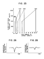
- these air charging rate of (A), (B), (C) and (D) are different each other in which are controlled by the microprocessor(17), which is composed to calculate a necessary heat load in response to these each elements of an airflow rate of the above, a feeding water temperature, a setting temperature, a hot-water discharging temperature, a heat efficiency of heat exchanger and a proportional gain and others, and to select a necessary airflow rate of (A), (B), (C) and (D) for each number of combustion capacity so as to make a speed-control of the common blower(38a) through an airflow-rate control-circuit within the above microprocessor(17).
- the necessary rotational frequency of the common blower (38a) is referred to Fig.23 in which shows a graph of relationship between the number of combustion capacity and the blower rotational frequency.
- this inventor offered the technology of controlling the airflow rate for combustion by means of a speed-control of a blower in proportion of the variation of a fuel gas volume.
- this inventor would like to offer an improved technology of providing a detecting means to detect the delay response of the blower, and in proportion to the actual variation of blowing capacity, the movement of a proportional valve is to be always synchronized with the actual variation of the blower.
- a sensor of airflow rate(43) will detect a rotational frequency of the blower motor(44), and a pulse-signal of proportionally controllable the rotation frequency will be dispatched.
- a control pannel(b) is arranged isolatedly from an water heater body(a), and provided a power source switch (18) and a temperature setting means(8).
- the temperature setting means(8) is a thing to set up an objective temperature of a hot-water discharge, and will dispatch a voltage pulse in compliance with the above set up temperature.
- each signal are, in Fig.24, accepted by the microprocessor(17) which is housed within the water heater body(a), and treated by a Central Processing Unit(CPU)(70).
- CPU Central Processing Unit
- CPU(70) will convert an input signal from a sensor of water volume(5) through an water volume detecting circuit(25) into an water data(Qh), and also an input signal from these of the temperature setting means(8), a sensor of feeding water temperature(6) and a sensor of hot-water discharging temperature(7) into a setting temperature data (Ts), a feeding water temperature data(Tc) and a hot-water discharging temperature(Th) respectively through an Analog-Digital Convertor(A/D convertor)(19) thereby, and in accordance with the above each data, CPU(70) will calculate a necessary heat load under following equations;
- an output signal from a sensor of airflow rate(43) is accepted by CPU(70) through an airflow rate detecting circuit(45), and it is converted into an airflow rate data(N).
- CPU(70) will calculate an objective rotational frequency(Ns) of the common blower(45) in response to the above necessary heat load, and then CPU(70) will dispatch an output signal of PI-control method to be controllable the blower rotation through a blower rotating output circuit(46) after calculation of comparision between the objective rotational frequency(Ns) and the airflow rate data(N), at the same time, the CPU(70) will calculate an objective opening(Ps) of No.1 proportional valve(12) and No.2 proportional valve(13) in response to the necessary heat load, and compare the above objective opening(Ps) to an airflow rate data(N), and dispatch an output signal of proportional valve's opening ratio in compliance with the above result of comparision with a rectified value in addition to the rectified value onto an objective opening through a proportional valve opening output circuit(47).
- blower rotational frequency(46) and the output circuit of proportional valve opening(47) will dispatch a suitable rotational frequency and a suitable opening respectively into each of a blower motor(44), proportional valves(12)(13) so as to operate them.
- this inventor offered a following technology of that it does not transmit the variation of a fuel gas feeding rate into a proportional gas valve, but it makes a proportional gas valve to coordinate its movement to the real step of the actual airflow rate of the blower.
- the essential part of D-type improved invention will be that the burner controlling means(21) was divided into those two sections as major of No.1 burner(2) and as minor of No.2 burner(3) respectively. According to this improvement within the software, it become to be possible to improve the sharp-drop of a hot-water discharging temperature during a switching time from No.2 burner(3) to No.1 burner.
- the above mentioned burner control means(21) is connected with No.2 burner(3) and No.1 burner(2) respectively, and when the burner selecting means(14) indicates to switch them from No.2 burner(3) combustion to No.1 burner(2) combustion, (No.2 burner combustion ⁇ No.1 burner combustion), it is composed to control so as to ignite No.1 burner(2) firstly and then laterly No:2 burner(3) is stopped.
- Fig.28 shows a temperature characteristicsof hot-water discharging temperature. As shown in those sections of (96) (97) of Fig.27, it has not an off-time of the burner, therefore, the sharp-drop of hot-water discharging temperature shown in Fig.28 is fairly improved comparing to the former case of Fig.26.
- No.1 invention as a proto-type was able to intensify the accomplishment of the series of intention of an instantaneous gas water heater in offering to those various kinds of improved technologies to prevent an air-cooled disadvantage of a heat excharger when a combustion air is forcedly charged by a blower attached in D-type improved invention and others, and to improve a temperature characteristics of a hot-water discharging temperature.
- a conventional type of a cold and hot showering system was composed to control the showering of cold and hot-water in the calculation of each necessary heat load by the operational section in accordance with those elements of which is arranged at a user's option after arrangement of all elements of a center temperature between both of a cold and hot showering temperature, the cycle of the showering, a swing wave span of showering temperature (a half amount of difference between the highest temperature and the lowest temperature), and a showering time-ratio of cold and hot showering (the time-ratio between a cold-water showering time and a hot-water showering time within one cycle of the rotation) and the other.
- the problem to be resolved hereby will be to scale up the controllable range to control in fixing of the cycle of cold and hot discharging water up to the highest limit range of the swing wave span as much as possible, and in case of excessing the above range, to control it with varying of the cycle.
- a cold and hot showering device in which is composed to connect a feeding water source with an instrument of a cold and hot showering laying between a feeding water channel provided a hot exchanger in the half way, and to discharge a high temperature hot-water and a lower temperature hot-water reciprocally from a cold and hot showering instrument with
- Fig.30 shows a composition of this practical example, and the function in the hardware will be similar to No.l invention or No.2 invention.
- the control pannel(b) provides a power source switch(18), No.1 operation switch(18a), an operation switch of a cold and hot showering(64), a temperature swing span setting section(65) and its display section, the swing span( ⁇ ) which is arranged in the above setting section(65) is converted to data( ⁇ ) through A/D convertor(19).
- the temperature swing span( ⁇ ) will be arranged with those eight steps of ⁇ 1 , ⁇ 2, ⁇ 3, ⁇ 4, ⁇ 5, ⁇ 6, ⁇ 7, ⁇ 8, and the swing span of each one step is 5°C and its steps up by 5°C per each step laterly.
- the microprocessor(17) is composed mainly by a microcomputer(67).
- the microcomputer(67) is composed basically by CPU(70), RAM(68)(random access memory) and ROM(69)(read only memory).
- CPU(70) will be written into ROM(69), therefore, CPU(70) will take in a necessary external data through an input-port(71) according to the above program, otherwise, gives and receives a data between RAM(68), in those ways, it calculates and treates, and as occasion demands, the treated data will be dispatched into an output-port(72).
- the output port(72) will receive an output port designated signal, and memorize it temporarily within the port, and further, release it into D/A convertor(19a). (digital-analog convertor)
- the D/A convertor(19a) will convert the digital signal given by the output port(72) to an analog signal for controlling a proportional valve and a electrical valve, and dispatch it into required No.1, No.2 propertional valves (12)(13) and No.1, No.2 electrical valves(10)(11).
- CPU(70) will calculate a necessary heat load, that is, the highest necessary heat load(F max.) to gain a high temperature side hot-water of the cold and hot water and also the lowest necessary heat load(F min.) to gain a lower temperature side water of the cold and hot water in accordance with the above an averaged necessary heat load (F i ), an arranged temperature swing span( ⁇ ) and an waterflow rate data.(the above are Step No.3, No.4)
- a program is provided preliminarily to be responsive so as to be driven by a twice time amplified feedback value.
- the burner is always commanded under the control of a necessary heat load which is suitable to the twice time amplified feedback value so that the burner will be able to accomplish for heating of a drastic high temperature on a cold water.
- the hardware section of this No.11 invention is composed based on Fig.1, and also same with No.10 invention.
- the bones of this invention will be summarized that a program of a cold and hot water temperature is written into the software so as to vary with a sharp gradient. Accordingly, explaining about a practical program, the program of which is written into ROM(69) will be shown in Fig. 33, and those data of a center temperature of a cold and hot waters, a cycle time and the discharging-ratio of a cold and hot showering are memorized as a fixed data, for example, the cycle time is 10 seconds and the discharging-ratio is 50%.
- CPU(70) will calculate a necessary heat load gainable high temperature hot-water(F+) including a twice time amplified feedback plus a standard necessary heat load by means of a feedforward value(Step No.4), in response to the above value, a heat capacity adjusting means is controlled, and then No.1 burner(2) is burned largely for 5 seconds with a corresponding heating capacity to the necessary heat load gainable high temperature hot water(F+). (Step No.5)
- Step No.6 a necessary heat load gainable low temperature hot-water(F-) by means of a feedforward method
- Step No.6 in compliance with the above value, a necessary burner will be select
- Step No.7 calculates a necessary heat load gainable low temperature hot-water(F-) including a standard necessary heat load by means of a feedforward plus a feedback value
- Step No.8 a heat capacity adjusting means is controlled in accordance with the above value, and No.2 burner(3) will be burned in small for 5 seconds with a corresponding heating capacity to the necessary heat load gainable low temperature hot-water(F-).
- this inventor has developed a following type of an attachment unit with a return by-pass line(c) which provides those of the check valve of the above, a vacuum breaker and other necessary apparatuses, furtherly a return by-pass pipe line system within the above attachment unit, when the multiple-purpose instantaneous gas water heater is installed with an additional works of an water supply facilities being needed, immediately install the above attachment unit(c) with the water heater body as an attachment, and instantly joints fixedly with those pipe line ends of a fuel gas pipe line, a feeding water pipe line and a hot-water discharging pipe line which are projected downward from the bottom of the water heater body(a) respectively to those pipe line ends of a fuel gas pipe line, a feeding water pipe line and a hot-water discharging pipe line which are projected upward from the top section of the attachment unit with a return by-pass line(c) respectively, in this way, it was developed to disuse the additional works of the above water supply facility, consequently, it became to be able to lighten an
- This attachment unit with a return by-pass line body(c) shown in Fig.l(B) provides those each pipe lines of a feeding water pipe line(4) of the water heater body(a), a hot-water discharging pipe line(34), a fuel gas pipe line(15) and also those pipe line of which are to be jointed with the above each pipe line respectively, saying a feeding water pipe line of the unit-top section(4a), a hot-water discharging pipe line of the unit top section(34a), a fuel gas pipe line of the unit top section(15c), and furtherly those pipe lines of a feeding water pipe line of the unit top section(4a), samely a hot-water discharging pipe line of the unit top section(34a), a fuel gas feeding pipe line of the unit top section(15c) are projected downward from the bottom of the unit(c) and at the end of the above projected pipe line, such a connector of a feeding water pipe line(4b), a connector of hot-water discharging pipe line (34c) and a
- a return by-pass line(32a) within the unit body will be connected with the above pipe line, and in the upstream side of the above connected section of a return by-pass line(32a) within the unit body, those apparatuses of a check valve within the unit(49a) and a vacuum breaker within the unit(73) are installed unifiedly into a case of a reducing valve(74) together, and then those unified apparatuses of the above are arranged in the upstream side of a return by-pass line(32a).
- a check valve within the unit(49b) will be arranged unifiedly with a feeding water pipe line(4b) of a feeding water pipe line of the unit top section(4a).
- the end of the return by-pass line within the unit(32a) is projected downward from the bottom of the attachment unit body(c), and a connector(75) is arranged at the end of the line in order to connect with a return by-pass line within the unit(32b).
- the return by-pass line within the unit(32a) provides a circulation pump within the unit(35a) in the halfway section of the above pipe line, and a waterflow switch within the unit(76) and a check valve with drain cock(77) are arranged in the upstream side of the above circulation pump (35a).
- this multiple-purpose instantaneous gas water heater is composed to connect mutually with each end of those pipe line (4), (34) and (15) which are projected downward from the bottom of the water heater and those each end of (4a), (34a) and (15c) which are projected upward from the top section of the attachment unit with return by-pass line(c), and further, those each connector of (4b) and (15b) which are projected downward from the bottom of the above attachment unit(c) will be connected with the building side each pipe line of (4c) and (25e), at the same time, according to connecting the connector(75) of the return by-pass line(32a) to the return by-pass line(32b) which is branched from a hot-water discharging pipe line(34c), in this way, such a multiple-purpose instantaneous gas water heater will be builded up in which provides unifiedly for a check valve(49a), a vacuum breaker(73), a reducing valve(74), a circulation pump(35a), an waterflow switch(76)
- this circulating water is maintained with a setting temperature or separately determined temperature by means of No.1, No.2 burners(2), (3) under control of the microprocessor(17) of said water heater body(a).
- the offered technology was limitted as only an attachment(c) to belong the water-heater body(a), however, such apparatuses or pipe line systems, that is, a check valve(49a), a vacuum breaker(73) and a detachable return by-pass line(32b) and others in which are installed within the attachment unit body (c) originally will be possible to install into the water-heater body(a) directly without a preparation of the attachment unit body(c) separately.
- this inventor will offer hereby a fresh technology relating to the display of the above temperature setting means and its display.
- the temperature setting means of a general type of an instantaneous gas water heater was roughly separated to around four step channels using a rotary type of switch with a predetermined temperature group, for example, low(around 35°C), suitable(around 42°C), hotter(around 60°C) and hottest(around 75°C), like those they were.
- the problem of which this invention is going to resolve will be to do so as to be able to set up a temperature mincingly nearby the temperature, especially a predetermined temperature as a suitable one.
- a technical means of which this invention is going to perform will be that, in such a type of an instantaneous gas water heater, it is provided for being able to select the predetermined temperature of which is determined as one of the factor of the above necessary heat load, and also, which are divided into four stages of a low, a suitable, a hotter and a hottest, and further, it is provided for selecting a preferable temperature out of those temperatures within a range of several degrees up and down temperature.
- a control pannel(b) provides for those apparatuses of a power source switch(18), No.2 operation switch(18a), No.1 fine-control temperature setting means(8a), No.2 fine-control temperature setting means( 8b ) and a setting temperature display section(78), and furtherly, the above control pannel(b) is connected with a microprocessor(17) electrically in which are arranged isolately from the control pannel(b).
- each a fine-control temperature setting means(8a), (8b) will select the set up temperature(Ts) out of those each optional temperature of 35°C, 42°C, 60°C and 75°C and additionally plus those each temperature within a range of 4°C toward up and down in the center temperature of 42°C, that is, 41°C, 40°C, 39°C and 38°C as downward, and 43°C, 44°C, 45°C and 46°C as upward for example, and furtherly, an optionally selected such a set up temperature(Ts) will be sent into A/D convertor(19) as a voltage current, and converted to a data(Ts) in there, and furtherly sent into the microprocessor (17), on the other hand, it indicates the set up temperature in the setting temperature display section(78).
- each push-button switch will be possible to change one step of the temperature by one-touch.
- the setting temperature display section(78) consists of a number of pilot-lamp using of a light emitting diode and the like in which are equivalent to a number of an optional set up temperature, and the pilot-lamps are illuminated in order according to the setting temperature.
- pilot-lamp for indicating the setting temperature in which 35°C is of low, 60°C is of hotter and 75°C is of hottest, and also those pilot-lamp are divided into nine steps within a range of between 38°C and 46°C with printed number and graduations.
- the control section is housed within the water heater body(a), it is consisted of a microprocessor(17) mainly.
- a microprocessor(17) is housed within the water heater body(a), and it has the operations means(9) for calculating a necessary heat load and also the burner selecting means(14) for determining what a burner by which a method of combustion being adoptable.
- the operations means(a) will take in an water volume data(Q) in conversion of a pulse signal coming from a sensor of water volume(5), and also take in those data of Ts, Tc and Th-transmitted from the fine-control temperature setting means (8a), (8b), a sensor of feeding water temperature(6) and a sensor of hot-water discharging temperature(7) respectively through A/D convertor(19), and then a necessary heat load(Fi) will be calculated in accordance with the above each data.
- the burner selecting means(14) will dispatch those necessary signals to No.1, No.2 electrical valves(10),(11), No.l, No.2 proportional control valves(12),(13) so as to perform the combustion by a necessary burner with a necessary method of the combustion in response to a necessary heat load(F 1 ) which is calculated by the above mentioned operations means(9).
- this inventor has furtherly developed newly not only to display a degree of a fine-control but also to display a trouble point with the winking of the lamps when any trouble occured in the water heater, and titles as G-type improved invention hereby, and detailes as follows;
- a various kinds of the matter detecting means are provided, and in case of the matter detected once, the burner combustion is stopped for security, and further, it is composed to generate an alarm for the user by means of display with a winking in use of a burner-lamp of the control pannel face which are in outside of the water heater body.
- the alarm consists of a temperature setting display means to light a pilot-lamp of which is predetermined and the matter detecting means to detect the matter of an water heater in connection with each kinds of safety device and each sensors of which are arranged respectively in the necessary place within the water heater, and further, the above pilot lamp of temperature setting display means is used for double purpose of the matter alarming, and the predetermined lamp will be made on-off in ' accordance with the kind of the matter detected by the matter detecting means.
- a predetermined lamp of alarming the above the matter will be lighten with winking among these lamps of the setting temperature display section when a kind of the matter is detected by one of detecting means, however, owing to be lighten with winking samely for this predetermined lamp, that is, it is merely a burner lamp even if the matter occured in another detecting means, therefore it is unable to know where of the matter arose, then it takes a lot of time for checking or repairing, and needs a pro-repair man for the check and the repair.
- the technical means to be performed by this invention for resolving the above problem will be to provide a number of pilot-lamp which are arranged visibly on the face of control pannel being outside of the water heater and are equivalent to the number of the temperature being able to arrange as the setting temperature, in case of arising another trouble in the detection, immediately another pilop-lamp will be lighten in order but not in the way of predetermined lamp illuminated.
- pilot-lamp which are arranged visibly on the face of control pannel being outside of the water heater and are equivalent to the number of the temperature being able to arrange as the setting temperature, in case of arising another trouble in the detection, immediately another pilop-lamp will be lighten in order but not in the way of predetermined lamp illuminated.
- this multiple-purpose instantaneous gas water heater consists of an water heater body(a) and an externally arranged control pannel(b), and the control pannel(c) provides those apparatuses of a power source switch(18) and No.2 operation switch(18b), and further, a microprocessor(17) will calculate a necessary heat load in accordance with those data of an waterflow rate and a feeding water temperature in which are detected by each of sensor of water volume(5) and a sensor of feeding water temperature(6) in which are arranged respectively along to a feeding water pipe line(4) of the water heater(a), and also by those both of a hot-water discharging temperature detected by a sensor of hot-water discharging temperature arranged along to a hot-water discharging pipe line(34) and the setting temperature arranged by the both of fine-control temperature setting means(8a) and (8b) on the face of the control pannel(b), after the above calculation, the combustion of No.l,-No.2 burners
- No.1, No.2 burners(2) (3) are provided as a combustion system, and burned one of them or either one of them in response to the necessary heat load, and furtherly the microprocessor(17) will select either of those control methods of which a control method to control the heating capacity in the variation of a fuel gas flow rate with the variation of opening degree of proportional valve(13) in response to the necessary heat load when only No.2 burner (3) was selected by the above microprocessor(17)(it is referred to as the proportional valve control method hereunder) and, as another one, such a control method to control the heating capacity with keeping of an opening degree of proportional valve in a constant degree and makes the length of on-off cycle and the time-ratio between on-time and off-time of the electrical valve(11) so as to vary the heating capacity, and repeat the on-off action(it is referred to as the intermittent combustion control method hereunder), and furtherly the above proportional control method will be selected when both of No.1, No.2 burners(2)(3) are operated combinationally
- this water heater(a) is composed so as to form a circulative loop line in which those pipe line channels of a hot-water discharging pipe line(34) which is worked into the building side and a feeding water pipe line(4) will be jointed in the halfway sections of each pipe line by a return by-pass line(32a) providing a circulation pump(35) along the line, and a contained water within the return by-pass line(32a) will be flowed circulatively by the operation of the circulation pump(35) when a hot-water discharge from the water heater body(a) is stopped, and the circulating water is maintained with a keeping-warm by the set up temperature or separately predetermined safe temperature, and to be able to ready to next discharge of hot-water.
- this water heater body(a) provides for those sensor of water volume(5), a sensor of feeding water temperature(6) and a sensor of hot-water discharging temperature, and additionally those two sensors of an airflow rate(53) and a flame sensor(82) for detecting a flame existence.
- the above sensor of airflow rate(53) will be arranged at the common blower(38a). which charges a necessary amount of combustion air into No.1, No.2 burners(2),(3), and the above flame sensor(82) are arranged facing to nearby No.1, No.2 burners(2), (3).
- a high-limit type of a bimetal-thermostat(80) and a thermal-fuse(81) are arranged nearby the heat exchanger(1) of this water heater body(a), and further, a sensor of waterflow(37b) is also applicated along to the return by-pass line(32a).
- each kind of sensors that is, a sensor of water volume(5), a sensor of feeding water temperature(6), a sensor of hot-water discharging temperature(7), a sensor of airflow rate(53), a flame sensor(82) -and other safety devices, saying a high-limit type of bimetal-thermostat(80), a termal- fuse(81) and a sensor of waterflow(37b) are connected wholly with the microprocessor (17) electrically and necessary signals are took into the microprocessor(17).
- a number of pilot-lamps are applicated with the numbers being equivalent to the number of visible setting temperature in the temperature setting sections(8a)(8b), and provides the setting temperature display section(78) to illuminate predetermined pilot-lamps in response to the set up temperature.
- the setting temperature are predetermined with four steps separated in a low, a suitable, a hotter and a hottest in due course, and as to those three zone of a low, a hotter and a hottest, they are limitted to be set up by one step per each zone, however, in the zone of a suitable, it were separated into nine steps mincingly so as to be set up.
- this temperature setting section(78) has twelve pieces of pilot lamps.
- those nine pieces of the lamp will display not only the setting temperature of a suitable zone but also it will be used to alarm the matter of the water heater, so that according to on-off lighting(winking) of those lamps, specially determined trouble point will be displayed.
- those nine pieces of lamps will be used for double purpose of alarming under following order; From the order of lower temperature side, no ignition alarm lamp(78a), miss-ignition alarm lamp(78b), high-limit bimetal-thermostat driven or thermal-fuse broken alarm lamp(78c), a feeding water sensing thermister cord broken or shorted alarm lamp(78d), a hot-water sensing thermistor cord broken or shorted alarm lamp(78e), airflow sensor or blower abnormal alarm lamp(78f), flame sensor abnormal alarm lamp(78g), circulation pump abnormal alarm lamp(78h) and waterflow sensor abnormal alarm lamp(78i).
- each alarm lamps from(78a) to (78i) will be illuminated with winking by laterly described alarm signal which are divided into nine pieces from No.1 to No.9 signals.
- the microprocesser(17) is composed of those well-known CPU, RAM and ROM basically, and many kinds of program are written into ROM for controlling CPU, and No.1, No.2 burners (2), (3) are controlled in accordance with the program of combustion control which is written in ROM, with the arithmetic-logical process of those signals coming from the above each sensor and the set-up temperature, and further, the above combustion is operated with a safety-control in accordance with the program of safety-control which is written in ROM.
- the abnormality detecting means(R) of the microprocessor(17) will makes a decision quickly for whether the safety devices are going well or not after the operation switch(18) of the control pannel(b) is turned to on, and in case of those circuits of the high-limit bimetal-thermostat(80) or the thermal fuse(81) were shorted, then No.3 alarm signal will be dispatched in this way, in case of breaking or a short in thermistor cord of sensor of feeding water, No.4 alarm signal is dispatched, and further, in case of breaking or a short in thermistor cord of sensor of hot-water discharge, No.5 alarm signal is dispatched.
- those alarm lamps are winking illuminated when No.3 alarm signal is dispatched for the high-limit and thermal fuse alarm lamp(78c), and No.4 alarm signal is dispatched for the breaking or a short of feeding water thermistor alarm lamp(78d) and No.4 alarm signal is dispatched for breaking or a short of hot-water thermistor alarm lamp(78e) respectively.
- the abnormality detecting means(R) will detect an existence of a electromotive force current of flame-rod by means of the flame-rod type sensor(82) when the faucet and the like(27) is released, and in case of no response to the current, quickly No.7 alarm signal is dispatched and a flame sensor abnormal alarm lamp(78g) will be winked.
- the abnormality detecting means(R) will detect those of abnormalities of the airflow sensor(43) or the common blower(38a) in accordance with the blower rotation which is detected by the airflow sensor(43), and in case of the blower rotation being less than 1.200 rpm, No.6 alarm signal will be dispatched and the airflow sensor abnormal or blower abnormal alarm lamp(78f) is winked.
- the abnormality detecting means(R) will detect the current ampere of the flame-rod type sensor(82) after an ignition-spark being made by the igniter(82), and if less than 1 ⁇ A of current ampere is continued during more than four seconds, at that time, No.1 alarm signal is dispatched and none-ignition alarm lamp(78a) is winked.
- abnormality detecting means(R) will chase the movement of flame current after ignition and if the current narrows toward the end, No.2 alarm signal is dispatched and the miss-ignition alarm lamp(78b) is winked.
- the abnormality detecting means(R) decides for whether a switch of a Keeping-warm operation(79) is turned to on or not, in case of the switch-on, then decides for whether the waterflow switch(76) is turned to on or not, and in case of the switch-on, No.9 alarm signal is dispatched for making a wink of an waterflow alarm lamp(78i).
- the microprocessor(17) will make largest of the blower rotation of the common blower(38a) and maintains the top rotation for between three seconds and seven seconds just after No.4 and No.5 alarm signals are dispatched, and also those of electrical valves(10)(11) and proportional valves (12)(13) are turned to off and also the common blower(38a) is operated with a top rotation for between three and seven seconds at the time of those No.1, No.2, No.6, No.7, No.8 and No.9 of each alarm signals are dispatched.
- No.1 invention consists of; No.1 burner; No.2 burner, wherein arranged together with the above No.1 burner against one unit of heat exchanger, and the highest combustion capacity is arranged as well as the lowest combustion capacity of No.1 burner, otherwise arranged slightly larger than it; those of water flow rate detecting means, a feeding water temperature detecting means and a hot-water temperature detecting means, wherein arranged respectively along to a feeding water pipe line channel passing through the heat exchanger; a control pannel, wherein provides a temperature setting means; an arithmetic-logic operations means to operate a necessary heat load in the microprocessor in accordance with those data of input from the above each detecting means and the temperature setting means; a burner selecting means to select an usable burner in accordance with a necessary heat load, wherein calculated by the arithmetic-logic operations means; a selectively generative means of those signals for a combustion-off signal, No.2 burner .
- No.3 invention is composed for; a usable burner is selected at the beginning by a feedforward combustion capacity which is properly decided finally as a necessary combustion capacity, therefore as the result, it is able to ignite a proper burner which ought to ignite from the beginning, so that unnecessary over-working of the burner was avoided.
- the burner is operated with an initially decided combustion capacity including the above feedback value, so that an immediate discharge of hot-water with a set up temperature will be done, and further, no igniting to another burner.
- a small capacity type burner is used to both of intermittent combustion and also proportional combustion, so that the durability of the small capacity type burner is improved.
- No.4 invention is composed for
- No.7 invention is composed of
- a small capacity type No.2 burner is operated with an intermittence or a continuous combustion
- a large capacity type No.1 burner is operated with a continuous combustion when a necessary heat load exceeds the highest ability of a small capacity type No.2 burner, therefore, it can control both of hot-water discharging temperature and circulative water temperature within a wide range of necessary heat load.
- No.9 invention has following advantage because of the above composition
- No.11 invention has following advantage because of the above composition
- A-type improved invention has following advantages because of the above composition
- a pipe line contained water is always heated up to a set up temperature, so that an immediate discharge of hot-water is available when opened hot-water-valve of discharging apparatuses. Therefore, the serviceableness is improved and no more water is threw away until hot-water discharged from the hot-water valve, so that it is economical.
- the temperature control of the hot-water is done by those time-ratio between on-time and off-time in an intermittent combustion, so that according to make small to the on-time against the off-time, the combustion number of burner can reduce to near No.0 so as to make combustion with an extremely smaller combustion capacity,in this connection, even if a difference temperature between setting temperature and circulating water temperature might be extremely small, still it can warm up to a setting temperature. Therefore, no more bumping or hunting are serious.
- B-type improved invention has following functions and effects
- Fig.15 shows a conventional temperature characteristics
- Fig.18 shows the temperature characteristics of this practical example.
- the drop of the temperature(B 2 ) becomes small, and then, the working time is shorten. Therefore, no more cold water attack to users at the beginning.
- C-type improved invention has following advantage because of the above composition; in this invention, the blower operation will be stopped when the off-time of intermittent combustion is continued for predetermined period, therefore, an ability of a keeping-warm is improved and a fuel and power consumption are reduced.
- D-type improved invention has following advantage because of the above composition; when it transits from a small capacity type burner to a large capacity type burner, an ignition of large capacity type burner is first and then later extinguish the small capacity type burner, so that none-combustion time is eliminated. Therefore, it has a few fall of hot-water temperature when it is discharged initially, and its serviceableness will be improved.
- E-type improved invention has following advantage because of the above composition; in this invention, an attachment unit is prepared, and those apparatuses of a feeding water pipe line, a hot-water discharging pipe line, a detouchable return by-pass line, a circulation pumps, a check valve, a vacuum breaker and other necessary apparatuses are housed within the attachment unit interior, therefore, jointing the above pipe lines of a feeding water and discharging hot-water with the same channels of building side, then no more conventional works of the above extra apparatuses installation will be required, so that the works-time of the installation will be shorten.
- F-type improved invention has following advantage because of the above composition; in this invention, as to how to set up temperature, it is composed of that in the range of frequent using temperature zone, saying a suitable zone of temperature will be controllable by a fine control way excepting another temperature zone of a low, a hotter and a hottest sections, therefore, its serviceableness will be improved.
- G-type improved invention has following advantages because of the above composition
Landscapes
- Engineering & Computer Science (AREA)
- Chemical & Material Sciences (AREA)
- Combustion & Propulsion (AREA)
- Mechanical Engineering (AREA)
- General Engineering & Computer Science (AREA)
- Physics & Mathematics (AREA)
- Thermal Sciences (AREA)
- Regulation And Control Of Combustion (AREA)
- Control Of Combustion (AREA)
- Feeding And Controlling Fuel (AREA)
Applications Claiming Priority (12)
| Application Number | Priority Date | Filing Date | Title |
|---|---|---|---|
| JP156593/85 | 1985-07-15 | ||
| JP60156593A JPS6217566A (ja) | 1985-07-15 | 1985-07-15 | ガス瞬間式給湯機 |
| JP60160770A JPS6222956A (ja) | 1985-07-19 | 1985-07-19 | ガス瞬間式給湯機 |
| JP160770/85 | 1985-07-19 | ||
| JP60166983A JPS6226416A (ja) | 1985-07-26 | 1985-07-26 | ガス瞬間式給湯機のガス比例弁制御装置 |
| JP166983/85 | 1985-07-26 | ||
| JP238850/85 | 1985-10-24 | ||
| JP60238850A JPS6298120A (ja) | 1985-10-24 | 1985-10-24 | ガス瞬間式給湯装置 |
| JP61003154A JPS62162848A (ja) | 1986-01-10 | 1986-01-10 | ガス瞬間式給湯装置 |
| JP61003153A JPS62162847A (ja) | 1986-01-10 | 1986-01-10 | ガス瞬間式給湯装置 |
| JP3154/86 | 1986-01-10 | ||
| JP3153/86 | 1986-01-10 |
Publications (3)
| Publication Number | Publication Date |
|---|---|
| EP0222972A2 true EP0222972A2 (de) | 1987-05-27 |
| EP0222972A3 EP0222972A3 (en) | 1987-07-01 |
| EP0222972B1 EP0222972B1 (de) | 1992-02-12 |
Family
ID=27547748
Family Applications (1)
| Application Number | Title | Priority Date | Filing Date |
|---|---|---|---|
| EP86109704A Expired - Lifetime EP0222972B1 (de) | 1985-07-15 | 1986-07-15 | Mehrzwecksofortwassererhitzer |
Country Status (4)
| Country | Link |
|---|---|
| US (2) | US4819587A (de) |
| EP (1) | EP0222972B1 (de) |
| KR (1) | KR910000677B1 (de) |
| DE (1) | DE3683892D1 (de) |
Cited By (5)
| Publication number | Priority date | Publication date | Assignee | Title |
|---|---|---|---|---|
| EP0279768B1 (de) * | 1987-02-20 | 1993-12-08 | Carrier Corporation | Kapazitätskontrolle für integrierten Ofen |
| AT403414B (de) * | 1993-06-14 | 1998-02-25 | Vaillant Gmbh | Verfahren zur kesselrücklauftemperatur-regelung |
| EP0884532A1 (de) * | 1997-06-11 | 1998-12-16 | Gaz De France (Service National) | Verfahren und Vorrichtung zur Regelung der Temperatur von einem in einem Brenner aufgeheizten Fluidum |
| EP2299184A3 (de) * | 2009-09-11 | 2016-11-30 | Woongjin Coway Co., Ltd. | Vorrichtung zur Bereitstellung von warmem Wasser und Verfahren dafür |
| CN114544868A (zh) * | 2022-01-20 | 2022-05-27 | 上海工程技术大学 | 一种消除干扰气体影响的气体检测方法与系统 |
Families Citing this family (74)
| Publication number | Priority date | Publication date | Assignee | Title |
|---|---|---|---|---|
| DE3738185C2 (de) * | 1987-11-10 | 1997-12-11 | Salm O & Co Gmbh | Vorrichtung zum Erwärmen von Braumaische |
| US5053978A (en) * | 1989-05-26 | 1991-10-01 | Jeffrey Solomon | Automatic boiler room equipment monitoring system |
| US5039007A (en) * | 1989-05-26 | 1991-08-13 | Wolter Gerald C | Water and air heating system |
| CA2172416A1 (en) * | 1996-03-22 | 1997-09-23 | Giovanni Dimarco | Combined hot water and space heater |
| US6109339A (en) * | 1996-07-15 | 2000-08-29 | First Company, Inc. | Heating system |
| RU2154233C1 (ru) * | 1999-04-19 | 2000-08-10 | Сушинский Валерий Адольфович | Способ защиты котельного агрегата и устройство для его осуществления |
| US6216685B1 (en) * | 1999-04-30 | 2001-04-17 | Gas Research Institute | Common venting of water heater and induced draft furnace |
| US7346274B2 (en) * | 1999-07-27 | 2008-03-18 | Bradenbaugh Kenneth A | Water heater and method of controlling the same |
| RU2206024C2 (ru) * | 2001-07-20 | 2003-06-10 | Открытое акционерное общество Таганрогский котлостроительный завод "Красный котельщик" | Способ длительного непрерывного автоматического определения остаточного ресурса элементов котла, работающих под давлением |
| US20030085021A1 (en) * | 2001-08-17 | 2003-05-08 | Dykes Ronald M. | Energy optimizer |
| CN103363672B (zh) * | 2003-02-19 | 2016-05-18 | 美国州际实业有限公司 | 热水器及其操作方法 |
| US20070006865A1 (en) | 2003-02-21 | 2007-01-11 | Wiker John H | Self-cleaning oven |
| US7152415B2 (en) * | 2004-03-18 | 2006-12-26 | Carrier Commercial Refrigeration, Inc. | Refrigerated compartment with controller to place refrigeration system in sleep-mode |
| US8087407B2 (en) | 2004-03-23 | 2012-01-03 | Middleby Corporation | Conveyor oven apparatus and method |
| US9585400B2 (en) | 2004-03-23 | 2017-03-07 | The Middleby Corporation | Conveyor oven apparatus and method |
| US7372005B2 (en) * | 2004-09-27 | 2008-05-13 | Aos Holding Company | Water storage device having a powered anode |
| GB2418724A (en) * | 2004-09-30 | 2006-04-05 | Energy Control Systems Ltd | Boiler control unit |
| US20080110279A1 (en) * | 2005-01-10 | 2008-05-15 | Waitek Limited | Energy/Water Usage Monitor |
| AU2012202470B2 (en) * | 2005-09-08 | 2013-08-01 | Primo-Tech Pty Ltd | Fluid Heater |
| US7644712B2 (en) * | 2005-11-09 | 2010-01-12 | Honeywell International Inc. | Negative pressure conditioning device and forced air furnace employing same |
| US7748375B2 (en) * | 2005-11-09 | 2010-07-06 | Honeywell International Inc. | Negative pressure conditioning device with low pressure cut-off |
| WO2007076962A1 (de) * | 2006-01-02 | 2007-07-12 | Ryll-Tech Gmbh | Heizbrenner |
| NZ590704A (en) * | 2006-03-24 | 2011-07-29 | Rheem Australia Pty Ltd | Maintaining a detected water flow at a predetermined temperature threshold by adjusting heaters |
| US7380523B2 (en) * | 2006-07-12 | 2008-06-03 | Emerson Electric Co. | Control for a fuel-fired water heating appliance having variable heating rates |
| US20080124667A1 (en) | 2006-10-18 | 2008-05-29 | Honeywell International Inc. | Gas pressure control for warm air furnaces |
| US8591221B2 (en) * | 2006-10-18 | 2013-11-26 | Honeywell International Inc. | Combustion blower control for modulating furnace |
| KR100805630B1 (ko) * | 2006-12-01 | 2008-02-20 | 주식회사 경동나비엔 | 가스보일러의 연소장치 |
| GB0624945D0 (en) * | 2006-12-14 | 2007-01-24 | Microgen Energy Ltd | A heating system |
| US8353463B2 (en) | 2007-04-24 | 2013-01-15 | Rinnai America Corporation | Methods and apparatus for heating air with hot water |
| EP2185871B1 (de) * | 2007-08-28 | 2016-11-23 | AOS Holding Company | Warmwasserspeicher mit tankzustandsüberwachungsmerkmalen |
| US8382003B2 (en) * | 2007-11-21 | 2013-02-26 | Lennox Industries Inc. | Method and system for controlling a modulating air conditioning system |
| US8070481B2 (en) | 2008-05-27 | 2011-12-06 | Honeywell International Inc. | Combustion blower control for modulating furnace |
| US9316413B2 (en) * | 2008-06-11 | 2016-04-19 | Honeywell International Inc. | Selectable efficiency versus comfort for modulating furnace |
| KR100985384B1 (ko) * | 2008-06-27 | 2010-10-05 | 주식회사 경동네트웍 | 온수 공급 시스템에서 저유량의 온수 사용시 온수 온도를제어하기 위한 방법 |
| US9317046B2 (en) * | 2008-07-03 | 2016-04-19 | Mike Gum | Variable output heating control system |
| US8123518B2 (en) | 2008-07-10 | 2012-02-28 | Honeywell International Inc. | Burner firing rate determination for modulating furnace |
| JP5154370B2 (ja) * | 2008-11-11 | 2013-02-27 | 株式会社パロマ | 給湯器 |
| US8839714B2 (en) | 2009-08-28 | 2014-09-23 | The Middleby Corporation | Apparatus and method for controlling a conveyor oven |
| DE102009048405A1 (de) * | 2009-10-06 | 2011-04-07 | Honeywell Technologies S.A.R.L. | Regeleinrichtung für Gasbrenner |
| DE102010010791A1 (de) * | 2010-03-09 | 2011-09-15 | Honeywell Technologies Sarl | Mischvorrichtung für einen Gasbrenner |
| US9513003B2 (en) * | 2010-08-16 | 2016-12-06 | Purpose Company Limited | Combustion apparatus, method for combustion control, board, combustion control system and water heater |
| AU2010358473B2 (en) * | 2010-10-21 | 2013-09-05 | Kyungdong Navien Co., Ltd. | Method for controlling a parallel operation of a multi-water heater |
| US8381689B2 (en) * | 2010-11-24 | 2013-02-26 | Grand Mate Co., Ltd | Method for examining water heater safety |
| CN103229006B (zh) * | 2010-12-22 | 2015-11-25 | 三菱电机株式会社 | 供热水空调复合装置 |
| US8560127B2 (en) | 2011-01-13 | 2013-10-15 | Honeywell International Inc. | HVAC control with comfort/economy management |
| US20120225395A1 (en) * | 2011-03-01 | 2012-09-06 | Haggerty Sean E | Method and system for limiting water boiler heat input |
| US8857736B1 (en) | 2011-09-29 | 2014-10-14 | Sioux Corporation | Washing system and method |
| US8876524B2 (en) | 2012-03-02 | 2014-11-04 | Honeywell International Inc. | Furnace with modulating firing rate adaptation |
| US20130328686A1 (en) * | 2012-06-07 | 2013-12-12 | Twin-Star International, Inc. | System and methods for monitoring heating elements |
| WO2014018564A1 (en) | 2012-07-23 | 2014-01-30 | Zieger Claus Dieter | Multiple proportion delivery systems and methods |
| JP2014047980A (ja) * | 2012-08-31 | 2014-03-17 | Noritz Corp | 潜熱回収型給湯装置 |
| US20150053151A1 (en) * | 2013-08-22 | 2015-02-26 | Therm-O-Disc, Incorporated | Fluid flow sensor and low flow cut-off device |
| JP6104880B2 (ja) * | 2014-12-25 | 2017-03-29 | リンナイ株式会社 | 連結給湯システム |
| US10802459B2 (en) | 2015-04-27 | 2020-10-13 | Ademco Inc. | Geo-fencing with advanced intelligent recovery |
| DE102015225581A1 (de) * | 2015-12-17 | 2017-06-22 | Convotherm Elektrogeräte GmbH | Verfahren zum Betreiben eines gewerblichen Gargeräts |
| US9945567B2 (en) * | 2016-01-26 | 2018-04-17 | Lennox Industries Inc. | Heating furnace using anti-stratification mode |
| JP6952985B2 (ja) * | 2017-05-25 | 2021-10-27 | 株式会社パロマ | 給湯器 |
| CN108589834B (zh) * | 2018-05-17 | 2020-03-10 | 哈尔滨工业大学 | 一种智能节水型一键启动恒温洗浴系统 |
| CN109945504A (zh) * | 2019-02-27 | 2019-06-28 | 邹雄宇 | 一种热水器和壁挂炉零冷水技术优化方法及系统 |
| JP7209347B2 (ja) * | 2019-03-07 | 2023-01-20 | パーパス株式会社 | 給湯装置、給湯プログラムおよび給湯方法 |
| US11846433B2 (en) * | 2019-09-27 | 2023-12-19 | Rheem Manufacturing Company | Heated water recirculation control |
| CA3107299A1 (en) | 2020-01-31 | 2021-07-31 | Rinnai America Corporation | Vent attachment for a tankless water heater |
| JP2021183888A (ja) * | 2020-05-22 | 2021-12-02 | リンナイ株式会社 | 燃焼装置 |
| US11754291B2 (en) | 2020-09-28 | 2023-09-12 | Midea Group Co., Ltd. | Modulating oven burner control for gas cooking appliance |
| CN119268138A (zh) * | 2021-01-14 | 2025-01-07 | 芜湖美的厨卫电器制造有限公司 | 燃气热水器及其控制方法、装置和计算机可读存储介质 |
| CN113325028B (zh) * | 2021-06-07 | 2022-05-24 | 中国核动力研究设计院 | 自然循环系统不稳定流动的沸腾临界实验装置及控制方法 |
| EP4155620B1 (de) | 2021-09-23 | 2025-01-08 | Pittway Sarl | Wassererhitzer und verfahren zum betreiben eines wassererhitzers |
| CN113932457B (zh) * | 2021-11-23 | 2023-03-31 | 华帝股份有限公司 | 燃气热水器燃烧工况与风速自动匹配的方法 |
| EP4219986A1 (de) | 2022-01-31 | 2023-08-02 | Pittway Sarl | 3-wege-fluidventil, vorrichtung zur handhabung eines fluidstroms mit einem 3-wege-ventil und wassererhitzer mit einem 3-wege-ventil und verfahren zu dessen betrieb |
| CN114543193B (zh) * | 2022-02-15 | 2024-08-20 | 北京小米移动软件有限公司 | 电控组件、空调室外机和空调系统 |
| CN114484885B (zh) * | 2022-02-17 | 2023-09-01 | 中国市政工程华北设计研究总院有限公司 | 一种以氢气为燃料的家用燃气热水器控制方法 |
| CN115597228B (zh) * | 2022-10-20 | 2024-05-24 | 珠海格力电器股份有限公司 | 燃气热水器、加热控制方法和装置 |
| CN115900092B (zh) * | 2022-11-16 | 2025-08-15 | 艾欧史密斯(中国)热水器有限公司 | 燃气热水装置及其控制方法 |
| CN116481188B (zh) * | 2023-04-21 | 2026-05-05 | 艾欧史密斯(中国)热水器有限公司 | 燃气热水装置的控制方法及燃气热水装置 |
Citations (2)
| Publication number | Priority date | Publication date | Assignee | Title |
|---|---|---|---|---|
| JPS58168840A (ja) | 1982-03-30 | 1983-10-05 | Noritsu Co Ltd | 瞬間湯沸器における能力制御装置 |
| US4501261A (en) | 1982-06-28 | 1985-02-26 | Toto Limited | Instantaneous gas water heater |
Family Cites Families (13)
| Publication number | Priority date | Publication date | Assignee | Title |
|---|---|---|---|---|
| FR1477667A (fr) * | 1966-03-08 | 1967-04-21 | Thomson Houston Comp Francaise | Perfectionnements aux systèmes de contrôle de la combustion de fluides, notamment dans les fours de raffineries |
| US3887325A (en) * | 1973-05-29 | 1975-06-03 | Sioux Steam Cleaner Corp | Control method and apparatus for burners |
| FR2330963A1 (fr) * | 1975-11-04 | 1977-06-03 | Saunier Duval | Dispositif de recyclage d'eau chaude sanitaire associable a un generateur individuel |
| JPS54108042A (en) * | 1978-02-10 | 1979-08-24 | Noritsu Co Ltd | Water boiler |
| US4184457A (en) * | 1978-03-27 | 1980-01-22 | Albin Trotter | Water flow responsive control for a liquid heater |
| CH641889A5 (de) * | 1980-02-04 | 1984-03-15 | Landis & Gyr Ag | Heizungsanlage. |
| DE3012750A1 (de) * | 1980-03-29 | 1981-11-19 | Joh. Vaillant Gmbh U. Co, 5630 Remscheid | Verfahren zur steuerung von waermequellen einer heizungsanlage und vorrichtung zur durchfuehrung des verfahrens |
| JPS56149546A (en) * | 1980-04-21 | 1981-11-19 | Gasutaa:Kk | Hot-water supplier |
| JPS5831249A (ja) * | 1981-08-19 | 1983-02-23 | Noritsu Co Ltd | 比例制御式湯沸器 |
| US4429682A (en) * | 1981-10-09 | 1984-02-07 | Huang Ming F | Automatic safety gas heating device |
| DE3143081A1 (de) * | 1981-10-30 | 1983-05-11 | Grundfos A/S, 8850 Bjerringbro | Brauchwasseranlage mit gesteuertem umwaelzpumpenaggregat |
| JPS59120845U (ja) * | 1983-02-04 | 1984-08-15 | リンナイ株式会社 | 湯沸器の燃焼制御回路 |
| GB2154727B (en) * | 1984-02-27 | 1987-06-24 | Rinnai Kk | Water heater |
-
1986
- 1986-06-28 KR KR1019860005209A patent/KR910000677B1/ko not_active Expired
- 1986-07-09 US US06/883,773 patent/US4819587A/en not_active Expired - Fee Related
- 1986-07-15 DE DE8686109704T patent/DE3683892D1/de not_active Expired - Fee Related
- 1986-07-15 EP EP86109704A patent/EP0222972B1/de not_active Expired - Lifetime
-
1989
- 1989-01-25 US US07/301,361 patent/US4922861A/en not_active Expired - Fee Related
Patent Citations (2)
| Publication number | Priority date | Publication date | Assignee | Title |
|---|---|---|---|---|
| JPS58168840A (ja) | 1982-03-30 | 1983-10-05 | Noritsu Co Ltd | 瞬間湯沸器における能力制御装置 |
| US4501261A (en) | 1982-06-28 | 1985-02-26 | Toto Limited | Instantaneous gas water heater |
Cited By (7)
| Publication number | Priority date | Publication date | Assignee | Title |
|---|---|---|---|---|
| EP0279768B1 (de) * | 1987-02-20 | 1993-12-08 | Carrier Corporation | Kapazitätskontrolle für integrierten Ofen |
| AT403414B (de) * | 1993-06-14 | 1998-02-25 | Vaillant Gmbh | Verfahren zur kesselrücklauftemperatur-regelung |
| EP0884532A1 (de) * | 1997-06-11 | 1998-12-16 | Gaz De France (Service National) | Verfahren und Vorrichtung zur Regelung der Temperatur von einem in einem Brenner aufgeheizten Fluidum |
| FR2764674A1 (fr) * | 1997-06-11 | 1998-12-18 | Gaz De France | Procede et dispositif associe de regulation de la temperature d'un fluide chauffe par un bruleur |
| EP2299184A3 (de) * | 2009-09-11 | 2016-11-30 | Woongjin Coway Co., Ltd. | Vorrichtung zur Bereitstellung von warmem Wasser und Verfahren dafür |
| CN114544868A (zh) * | 2022-01-20 | 2022-05-27 | 上海工程技术大学 | 一种消除干扰气体影响的气体检测方法与系统 |
| CN114544868B (zh) * | 2022-01-20 | 2024-03-26 | 上海工程技术大学 | 一种消除干扰气体影响的气体检测方法与系统 |
Also Published As
| Publication number | Publication date |
|---|---|
| US4922861A (en) | 1990-05-08 |
| KR870001449A (ko) | 1987-03-13 |
| EP0222972A3 (en) | 1987-07-01 |
| DE3683892D1 (de) | 1992-03-26 |
| US4819587A (en) | 1989-04-11 |
| KR910000677B1 (ko) | 1991-01-31 |
| EP0222972B1 (de) | 1992-02-12 |
Similar Documents
| Publication | Publication Date | Title |
|---|---|---|
| US4819587A (en) | Multiple-purpose instantaneous gas water heater | |
| US4519540A (en) | Sealed gas heater with forced draft and regulation by microprocessor | |
| EP0154818A1 (de) | Regelsystem für eine Verbrennung mit erzwungenem Abzug | |
| US4350144A (en) | Hot water heating system | |
| EP0532339A1 (de) | Nudelkochgerät | |
| US4470541A (en) | Control system for low mass hydronic boilers | |
| JPS60216142A (ja) | 2缶2水式給湯暖房機の湯温制御装置 | |
| KR100283131B1 (ko) | 복합급탕장치 | |
| US20220090823A1 (en) | Dynamically Adjusting Heater | |
| JPH04251110A (ja) | ガス種判別方法及びこれを実施する燃焼装置 | |
| IES74694B2 (en) | A control system for gas cooker | |
| JPH11141979A (ja) | 一缶二水路式給湯装置 | |
| JP2634624B2 (ja) | 給湯器の出湯温度制御方法 | |
| JPS5777821A (en) | Combustion controller | |
| JP3215557B2 (ja) | 燃焼装置 | |
| JPH11173546A (ja) | 燃焼機器の燃焼制御方法および燃焼制御装置 | |
| JPS576236A (en) | Combustion unit | |
| JPS5694145A (en) | Hot water heater | |
| JPS5462104A (en) | Controlling method for combustion at hot stove of blast furnace | |
| GB2165347A (en) | Burner air/gas ratio control | |
| JPH0436548A (ja) | 暖房装置 | |
| JPS5910524Y2 (ja) | 床下等への収納形湯沸器 | |
| KR930001845B1 (ko) | 가스보일러에서의 강제소화타이머 작동 후 재점화시 연소제어방법 | |
| JPS61116237A (ja) | ガス瞬間式給湯機 | |
| JP3862807B2 (ja) | 給湯装置 |
Legal Events
| Date | Code | Title | Description |
|---|---|---|---|
| PUAI | Public reference made under article 153(3) epc to a published international application that has entered the european phase |
Free format text: ORIGINAL CODE: 0009012 |
|
| PUAL | Search report despatched |
Free format text: ORIGINAL CODE: 0009013 |
|
| AK | Designated contracting states |
Kind code of ref document: A2 Designated state(s): DE FR GB IT NL |
|
| AK | Designated contracting states |
Kind code of ref document: A3 Designated state(s): DE FR GB IT NL |
|
| 17P | Request for examination filed |
Effective date: 19871104 |
|
| 17Q | First examination report despatched |
Effective date: 19890509 |
|
| GRAA | (expected) grant |
Free format text: ORIGINAL CODE: 0009210 |
|
| AK | Designated contracting states |
Kind code of ref document: B1 Designated state(s): DE FR GB IT NL |
|
| PG25 | Lapsed in a contracting state [announced via postgrant information from national office to epo] |
Ref country code: IT Free format text: LAPSE BECAUSE OF FAILURE TO SUBMIT A TRANSLATION OF THE DESCRIPTION OR TO PAY THE FEE WITHIN THE PRE;WARNING: LAPSES OF ITALIAN PATENTS WITH EFFECTIVE DATE BEFORE 2007 MAY HAVE OCCURRED AT ANY TIME BEFORE 2007. THE CORRECT EFFECTIVE DATE MAY BE DIFFERENT FROM THE ONE RECORDED.SCRIBED TIME-LIMIT Effective date: 19920212 Ref country code: NL Effective date: 19920212 Ref country code: FR Effective date: 19920212 |
|
| REF | Corresponds to: |
Ref document number: 3683892 Country of ref document: DE Date of ref document: 19920326 |
|
| EN | Fr: translation not filed | ||
| NLV1 | Nl: lapsed or annulled due to failure to fulfill the requirements of art. 29p and 29m of the patents act | ||
| PLBE | No opposition filed within time limit |
Free format text: ORIGINAL CODE: 0009261 |
|
| STAA | Information on the status of an ep patent application or granted ep patent |
Free format text: STATUS: NO OPPOSITION FILED WITHIN TIME LIMIT |
|
| 26N | No opposition filed | ||
| PGFP | Annual fee paid to national office [announced via postgrant information from national office to epo] |
Ref country code: GB Payment date: 19950710 Year of fee payment: 10 |
|
| PGFP | Annual fee paid to national office [announced via postgrant information from national office to epo] |
Ref country code: DE Payment date: 19950713 Year of fee payment: 10 |
|
| PG25 | Lapsed in a contracting state [announced via postgrant information from national office to epo] |
Ref country code: GB Effective date: 19960715 |
|
| GBPC | Gb: european patent ceased through non-payment of renewal fee |
Effective date: 19960715 |
|
| PG25 | Lapsed in a contracting state [announced via postgrant information from national office to epo] |
Ref country code: DE Effective date: 19970402 |