EP0223068A2 - Ferrure pour battant coulissant pour fenêtre, porte ou similaire - Google Patents
Ferrure pour battant coulissant pour fenêtre, porte ou similaire Download PDFInfo
- Publication number
- EP0223068A2 EP0223068A2 EP86114310A EP86114310A EP0223068A2 EP 0223068 A2 EP0223068 A2 EP 0223068A2 EP 86114310 A EP86114310 A EP 86114310A EP 86114310 A EP86114310 A EP 86114310A EP 0223068 A2 EP0223068 A2 EP 0223068A2
- Authority
- EP
- European Patent Office
- Prior art keywords
- rail
- section
- pin
- slider
- bore
- Prior art date
- Legal status (The legal status is an assumption and is not a legal conclusion. Google has not performed a legal analysis and makes no representation as to the accuracy of the status listed.)
- Granted
Links
Images

Classifications
-
- E—FIXED CONSTRUCTIONS
- E05—LOCKS; KEYS; WINDOW OR DOOR FITTINGS; SAFES
- E05D—HINGES OR SUSPENSION DEVICES FOR DOORS, WINDOWS OR WINGS
- E05D15/00—Suspension arrangements for wings
- E05D15/06—Suspension arrangements for wings for wings sliding horizontally more or less in their own plane
- E05D15/10—Suspension arrangements for wings for wings sliding horizontally more or less in their own plane movable out of one plane into a second parallel plane
- E05D15/1005—Suspension arrangements for wings for wings sliding horizontally more or less in their own plane movable out of one plane into a second parallel plane the wing being supported on arms movable in horizontal planes
- E05D15/1013—Suspension arrangements for wings for wings sliding horizontally more or less in their own plane movable out of one plane into a second parallel plane the wing being supported on arms movable in horizontal planes specially adapted for windows
- E05D15/1015—Suspension arrangements for wings for wings sliding horizontally more or less in their own plane movable out of one plane into a second parallel plane the wing being supported on arms movable in horizontal planes specially adapted for windows with an intermediate tilt position
-
- E—FIXED CONSTRUCTIONS
- E05—LOCKS; KEYS; WINDOW OR DOOR FITTINGS; SAFES
- E05D—HINGES OR SUSPENSION DEVICES FOR DOORS, WINDOWS OR WINGS
- E05D15/00—Suspension arrangements for wings
- E05D15/06—Suspension arrangements for wings for wings sliding horizontally more or less in their own plane
- E05D15/10—Suspension arrangements for wings for wings sliding horizontally more or less in their own plane movable out of one plane into a second parallel plane
- E05D2015/1028—Suspension arrangements for wings for wings sliding horizontally more or less in their own plane movable out of one plane into a second parallel plane with only the wing moving transversely
- E05D2015/1031—Suspension arrangements for wings for wings sliding horizontally more or less in their own plane movable out of one plane into a second parallel plane with only the wing moving transversely the wing supported on arms extending from the carriage
-
- E—FIXED CONSTRUCTIONS
- E05—LOCKS; KEYS; WINDOW OR DOOR FITTINGS; SAFES
- E05Y—INDEXING SCHEME ASSOCIATED WITH SUBCLASSES E05D AND E05F, RELATING TO CONSTRUCTION ELEMENTS, ELECTRIC CONTROL, POWER SUPPLY, POWER SIGNAL OR TRANSMISSION, USER INTERFACES, MOUNTING OR COUPLING, DETAILS, ACCESSORIES, AUXILIARY OPERATIONS NOT OTHERWISE PROVIDED FOR, APPLICATION THEREOF
- E05Y2900/00—Application of doors, windows, wings or fittings thereof
- E05Y2900/10—Application of doors, windows, wings or fittings thereof for buildings or parts thereof
- E05Y2900/13—Type of wing
- E05Y2900/148—Windows
Definitions
- the invention relates to a fitting for a sliding wing designed in the form of a window, door or the like, which is carried by two carriages guided in frame-side longitudinal rails, each of which has a support arm which can be pivoted transversely to the rail direction by means of the wing operating lever, the outer end of which on the wing attacks, which is held in the region of its upper edge by folding scissors, one of which scissors arm with an upward-pointing pin, projecting from below through the slot of a running rail, rotatably and positively engages in the bore of a slide running in the rail and is releasably secured in this bore .
- the object of the invention is based on the design of a generic fitting in a technically simple manner so that the management relationships are improved.
- the guide ribs of the rails seen in cross section, have convex longitudinal flanks which fit in the throats in the middle region of the slide side walls and the bore of the slide is enlarged in cross section to the underside, in which larger cross section a concentric to the pin Threaded adjusting sleeve occurs and the pin is tied displaceably in the axial direction.
- a generic fitting is specified which is distinguished by a higher utility value.
- the guiding conditions of the slide receiving the pin in the running rail are optimal. Tilting of the slide in its guide cannot occur, so that the trouble-free displacement of the sliding sash is favored. Furthermore, the slider cannot inadvertently come down from the slot of the track. The slide must always be inserted from the front of the rail.
- the threaded adjusting bush located in the larger cross-section of the slider allows adjustability, so that dimensional deviations in installation are safely absorbed without impairing good guidance.
- the pin can also not leave the associated bore of the slider, which increases the security value of the fitting.
- a favorable feature is that the slider engages under the rail lower edge with shoulders. This measure proves to be particularly stable under load, since loads acting in the upward direction are additionally introduced via the shoulders into the lower edge of the rail, relieving the ribs / throat guide.
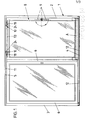
- the numeral 1 denotes a fixed frame, which is composed of the two vertical frame legs 2, 3 and the horizontal frame legs 4, 5, which are connected to each other in the middle by a further vertical frame leg 6. It is therefore possible to add a fixed door leaf 7 to the fixed frame 1 on the left-hand side and a sliding leaf 8 on the right-hand side organize. The latter can be parked parallel to itself from its closed position and pushed into the position covering the wing 7.
- the sliding sash 8 has an operating lever 9 on its vertical frame leg 2 on the right. If this takes its downward, solid line position, this corresponds to the closed position of the sliding sash 8. If the operating lever 9 turns 90 ° clockwise pivoted. the lower frame leg of the sliding sash 8 remains in contact with the fixed frame, while the opening scissors 10 provided on the upper frame leg pivot and guide the sliding sash 8 into the tilted position. A further displacement of the operating lever 9 then leads to the sliding leaf 8 being parked in parallel. Then it can be displaced by means of the running rails 11, 12 fastened to the horizontal frame legs 4, 5.
- the running rail 12 is assigned to the sliding sash 8, not shown, guided by a cover rail A, each of which has a cross arm that can be pivoted transversely to the direction of the rail, which can be actuated by means of the wing operating lever 9 , with the interposition of drive rods 13.
- the latter are in a frame groove 14 of the sliding sash 8 and are covered by a faceplate 15.
- the drive rod 13 assigned to the upper horizontal leg 16 of the sliding sash controls a scissor arm 17, which in turn directs the scissor arm 18 which has a Z-shaped cross section.
- the latter is hinged to the cover rail 15 in a known manner and carries at its end opposite the articulation point an upwardly directed pin 19 which is fixed by riveting on the scissor arm 18, cf. in particular FIG. 3.
- the pin 19 lies with the pin a larger cross section 20 on the top of this scissor arm 18.
- a stepped section 21 adjoins the cross-sectionally larger collar 20. At its free end, this section 21 forms an annular groove 22, the groove side walls 22 'of which widen outwards.
- a head 23 is formed with a truncated cone-shaped outer surface.
- a slider 24 is used to receive the pin 19.
- Throats 27 are provided on the two opposite slider side walls 25, 26 in the central region, which pass over shoulders 28 into a wider lower section 29.
- a hole 31 is machined in the middle, which merges into a larger cross section 32 with an internal thread.
- a threaded adjusting sleeve 33 engages in the larger cross-section 32, which in turn comprises the pin 19 at approximately half its length.
- the threaded adjusting sleeve 33 also forms a collar 34 which is supported on the top of the scissor arm 18.
- a bolt 35 which can be displaced in the longitudinal direction of the slide piece is used.
- a longitudinal bore 37 crossing the bore 31 is worked in from one end face 36 of the slide piece 24, which bore hole is located just before the transition point to the bore 31 merges into a bore section 37 ′ with a reduced cross section.
- the bolt 35 forms a stepped end portion 35 '.
- the latter is dimensioned so long that in the stop position of the bolt 35 the end face of the end section 35 'touches the bottom of the annular groove 22, but does not exert any clamping pressure on the pin 19.
- the diameter of the bolt end section 35 ' is smaller than the length of the annular groove 22.
- the longitudinal bore 37 is closed at the end by a stopper 38 indicated by a dot-dash line.
- a grub screw 39 which engages in a threaded bore 40 extending from the underside 30 of the slider, serves to hold the bolt 35 in its engaged position.
- the inside end of the grub screw 39 is provided with a taper 39 ', which in turn acts on the conical end 35 "of the bolt 35 and thus holds it in its captive position.
- the grub screw 39 forms an annular groove 41 on its central section As soon as this annular groove becomes visible when the grub screw 39 is unscrewed, this means that the bolt 35 is freely displaceable in its bore 37.
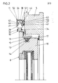
- the slide 11 receiving the slider 24 is approximately U-shaped in cross section.
- the outer U-leg 42 and the inner U-leg 43 form guide ribs 44, 45 which have convex longitudinal flanks which enter the throats 27 in a suitable manner.
- the U-legs 42, 43 are gripped at their lower edge by the shoulders 28 of the slide 24, cf. in particular FIG. 4.
- the U-leg 43 is wider than the other U-leg 42. It forms a slot 46 running parallel to the upper frame leg 16. Spacers 47 engage in this. Each of them is penetrated by a fastening screw 48. So that the fastening screws 48 can be used, the U-legs 42, 43 form a bore 49, which is closed by a stopper 50 after the fastening screw has been attached.
- guide ribs 52 are attached to the upper side 51 of the slider 24, which are supported on the U-web of the running rail 11.
Landscapes
- Engineering & Computer Science (AREA)
- Mechanical Engineering (AREA)
- Hinges (AREA)
- Window Of Vehicle (AREA)
- Wing Frames And Configurations (AREA)
- Support Devices For Sliding Doors (AREA)
- Specific Sealing Or Ventilating Devices For Doors And Windows (AREA)
- Curtains And Furnishings For Windows Or Doors (AREA)
- Building Environments (AREA)
- Operating, Guiding And Securing Of Roll- Type Closing Members (AREA)
- Seal Device For Vehicle (AREA)
- Working-Up Tar And Pitch (AREA)
- Polymers With Sulfur, Phosphorus Or Metals In The Main Chain (AREA)
- Securing Of Glass Panes Or The Like (AREA)
Priority Applications (1)
| Application Number | Priority Date | Filing Date | Title |
|---|---|---|---|
| AT86114310T ATE51054T1 (de) | 1985-11-14 | 1986-10-23 | Beschlag fuer einen in form eines fensters, tuere oder dergleichen ausgebildeten schiebefluegel. |
Applications Claiming Priority (2)
| Application Number | Priority Date | Filing Date | Title |
|---|---|---|---|
| DE3540347A DE3540347C1 (de) | 1985-11-14 | 1985-11-14 | Beschlag fuer einen in Form eines Fensters,Tuere oder dergleichen ausgebildeten Schiebefluegel |
| DE3540347 | 1985-11-14 |
Publications (3)
| Publication Number | Publication Date |
|---|---|
| EP0223068A2 true EP0223068A2 (fr) | 1987-05-27 |
| EP0223068A3 EP0223068A3 (en) | 1987-12-02 |
| EP0223068B1 EP0223068B1 (fr) | 1990-03-14 |
Family
ID=6285939
Family Applications (1)
| Application Number | Title | Priority Date | Filing Date |
|---|---|---|---|
| EP86114310A Expired - Lifetime EP0223068B1 (fr) | 1985-11-14 | 1986-10-23 | Ferrure pour battant coulissant pour fenêtre, porte ou similaire |
Country Status (7)
| Country | Link |
|---|---|
| EP (1) | EP0223068B1 (fr) |
| AT (1) | ATE51054T1 (fr) |
| DE (2) | DE3540347C1 (fr) |
| DK (1) | DK156083C (fr) |
| FI (1) | FI81880C (fr) |
| IE (1) | IE59484B1 (fr) |
| NO (1) | NO161186C (fr) |
Cited By (1)
| Publication number | Priority date | Publication date | Assignee | Title |
|---|---|---|---|---|
| FR2810068A1 (fr) | 2000-05-31 | 2001-12-14 | Ser Lee Neo | Construction de fenetre"double fonctions de pivoter ou de coulisser" |
Families Citing this family (3)
| Publication number | Priority date | Publication date | Assignee | Title |
|---|---|---|---|---|
| CN1229242C (zh) * | 2000-09-27 | 2005-11-30 | 因蒂尔汽车封闭装置公司 | 窗调节器槽的滑块装置 |
| EP1876319B1 (fr) | 2006-07-06 | 2014-10-15 | HAUTAU GmbH | Coulisseau de guidage pour panneaux coulissants ou déplaçables selon un plan parallèle |
| DE102009031939C5 (de) * | 2009-07-07 | 2024-11-07 | BRUSA Koltuk ve İç Trim Teknolojileri San. Tic. A.Ş | Gleitstein |
Family Cites Families (6)
| Publication number | Priority date | Publication date | Assignee | Title |
|---|---|---|---|---|
| DE2334767C2 (de) * | 1973-07-09 | 1984-07-12 | Wilh. Frank Gmbh, 7022 Leinfelden-Echterdingen | Schiebefenster mit mindestens einem horizontal verschiebbaren Flügel |
| FR2254222A5 (en) * | 1973-12-10 | 1975-07-04 | Silam | Overhead gear for suspended sliding door - has I-section slide bar on door top fitting into box rail |
| DE2648344C3 (de) * | 1976-10-26 | 1986-07-31 | Weikert, geb. Senft, Karoline, 3210 Elze | Beschlag für Schiebefenster, Schiebetüren o.dgl. |
| DE2700598C2 (de) * | 1977-01-08 | 1985-08-08 | Carl Fuhr Gmbh & Co, 5628 Heiligenhaus | Schiebefenster |
| DE2911875A1 (de) * | 1979-03-26 | 1981-02-26 | Softline Ag | Aufhaengevorrichtung fuer eine verschiebbare wandtafel einer schiebetrennwand |
| FR2557624B1 (fr) * | 1984-01-04 | 1986-05-02 | Faiveley Ets | Dispositif de suspension et de guidage d'un panneau mobile, notamment d'une porte louvoyante |
-
1985
- 1985-11-14 DE DE3540347A patent/DE3540347C1/de not_active Expired
-
1986
- 1986-10-23 AT AT86114310T patent/ATE51054T1/de not_active IP Right Cessation
- 1986-10-23 DE DE8686114310T patent/DE3669556D1/de not_active Expired - Lifetime
- 1986-10-23 EP EP86114310A patent/EP0223068B1/fr not_active Expired - Lifetime
- 1986-11-11 DK DK537486A patent/DK156083C/da active
- 1986-11-12 FI FI864594A patent/FI81880C/fi not_active IP Right Cessation
- 1986-11-13 NO NO864536A patent/NO161186C/no unknown
- 1986-11-13 IE IE299786A patent/IE59484B1/en not_active IP Right Cessation
Cited By (1)
| Publication number | Priority date | Publication date | Assignee | Title |
|---|---|---|---|---|
| FR2810068A1 (fr) | 2000-05-31 | 2001-12-14 | Ser Lee Neo | Construction de fenetre"double fonctions de pivoter ou de coulisser" |
Also Published As
| Publication number | Publication date |
|---|---|
| DK537486D0 (da) | 1986-11-11 |
| FI864594A0 (fi) | 1986-11-12 |
| DK156083C (da) | 1989-11-13 |
| DK156083B (da) | 1989-06-19 |
| IE59484B1 (en) | 1994-03-09 |
| FI864594L (fi) | 1987-05-15 |
| EP0223068B1 (fr) | 1990-03-14 |
| NO161186B (no) | 1989-04-03 |
| IE862997L (en) | 1987-05-14 |
| FI81880C (fi) | 1990-12-10 |
| NO864536D0 (no) | 1986-11-13 |
| NO864536L (no) | 1987-05-15 |
| FI81880B (fi) | 1990-08-31 |
| EP0223068A3 (en) | 1987-12-02 |
| ATE51054T1 (de) | 1990-03-15 |
| DE3540347C1 (de) | 1987-02-26 |
| DE3669556D1 (de) | 1990-04-19 |
| NO161186C (no) | 1989-07-12 |
| DK537486A (da) | 1987-05-15 |
Similar Documents
| Publication | Publication Date | Title |
|---|---|---|
| EP2107199A2 (fr) | Armature pour un battant au moins pivotant et/ou basculant parallèlement d'une fenêtre, d'une porte ou analogue | |
| DD297317A5 (de) | Moebelstueck mit versenkbarer tuere | |
| DE2301652A1 (de) | Ausstellvorrichtung fuer die fluegel von fenstern, tueren od.dgl., insbesondere von dreh-kippfluegeln | |
| AT402086B (de) | Beschlag für türen, fenster oder dergleichen | |
| DE19521539A1 (de) | Drehlager, insbesondere Scherenlager eines Drehbeschlags oder Dreh-Kippbeschlags für Fenster, Türen oder dergleichen | |
| EP0223068B1 (fr) | Ferrure pour battant coulissant pour fenêtre, porte ou similaire | |
| EP3420166B1 (fr) | Dispositif anti-relèvement pour un battant à coulissement parallèle se présentant sous forme d'oscillo-battant coulissant ou de battant coulissant | |
| EP0609526B1 (fr) | Dispositif pour connecter un bras de compas avec un chambranle de fenêtre ou de porte | |
| DE8707044U1 (de) | Beschlag für einen mittels Ausstellarm abstellbaren Schiebeflügel für Fenster, Türen o. dgl. | |
| DE9207012U1 (de) | Zusatzverriegelung für Fenster, Türen o.dgl. | |
| DE963933C (de) | Beschlag fuer Tueren, Fenster od. dgl., deren Fluegel wahlweise um eine lotrechte Achse schwenkbar oder um eine waagerechte Achse kippbar ist | |
| DE2410870A1 (de) | Laufrolle fuer einen schiebefluegel | |
| EP0429981B1 (fr) | Ferrure arrangée en feuillure pour portes ou fenêtres oscillo-battantes, en particulier avec encadrement en bois | |
| DE102019211793A1 (de) | Beschlaganordnung für ein barrierefreies Schiebefenster oder eine barrierefreie Schiebetür | |
| DE2904986A1 (de) | Feststellvorrichtung fuer kippbare fluegel | |
| DE29600891U1 (de) | Sicherungseinrichtung | |
| EP0355449B1 (fr) | Dispositif pour ajuster un panneau, au moins levable, d'une fenêtre, d'une porte ou analogue | |
| DE2759387C1 (de) | Beschlag fuer Fluegel von Fenstern,Tueren oder dergleichen,insbesondere Drehkippfluegel | |
| DE8707221U1 (de) | Treibstangenbeschlag für Fenster, Türen od.dgl. | |
| DE965867C (de) | Beschlag fuer Tueren, Fenster od. dgl., deren Fluegel um eine lotrechte Achse geschwenkt oder um eine waagerechte Achse gekippt werden koennen | |
| EP3511493B1 (fr) | Système de porte coulissante | |
| DE947230C (de) | Beschlag fuer Tueren, Fenster od. dgl., deren Fluegel wahlweise um eine lotrechte Achse geschwenkt oder um eine waagerechte Achse gekippt werden koennen | |
| DE1456348A1 (de) | Schiebetuere | |
| EP0827703A1 (fr) | Ferrure pour la fixation réglable d'un panneau frontal | |
| DE1213290B (de) | Beschlag fuer Fensterfluegel |
Legal Events
| Date | Code | Title | Description |
|---|---|---|---|
| PUAI | Public reference made under article 153(3) epc to a published international application that has entered the european phase |
Free format text: ORIGINAL CODE: 0009012 |
|
| AK | Designated contracting states |
Kind code of ref document: A2 Designated state(s): AT BE CH DE FR GB IT LI LU NL SE |
|
| PUAL | Search report despatched |
Free format text: ORIGINAL CODE: 0009013 |
|
| AK | Designated contracting states |
Kind code of ref document: A3 Designated state(s): AT BE CH DE FR GB IT LI LU NL SE |
|
| 17P | Request for examination filed |
Effective date: 19880311 |
|
| 17Q | First examination report despatched |
Effective date: 19890426 |
|
| GRAA | (expected) grant |
Free format text: ORIGINAL CODE: 0009210 |
|
| AK | Designated contracting states |
Kind code of ref document: B1 Designated state(s): AT BE CH DE FR GB IT LI LU NL SE |
|
| PG25 | Lapsed in a contracting state [announced via postgrant information from national office to epo] |
Ref country code: IT Free format text: LAPSE BECAUSE OF FAILURE TO SUBMIT A TRANSLATION OF THE DESCRIPTION OR TO PAY THE FEE WITHIN THE PRE;WARNING: LAPSES OF ITALIAN PATENTS WITH EFFECTIVE DATE BEFORE 2007 MAY HAVE OCCURRED AT ANY TIME BEFORE 2007. THE CORRECT EFFECTIVE DATE MAY BE DIFFERENT FROM THE ONE RECORDED.SCRIBED TIME-LIMIT Effective date: 19900314 Ref country code: BE Effective date: 19900314 Ref country code: SE Effective date: 19900314 Ref country code: NL Effective date: 19900314 |
|
| REF | Corresponds to: |
Ref document number: 51054 Country of ref document: AT Date of ref document: 19900315 Kind code of ref document: T |
|
| ET | Fr: translation filed | ||
| REF | Corresponds to: |
Ref document number: 3669556 Country of ref document: DE Date of ref document: 19900419 |
|
| GBT | Gb: translation of ep patent filed (gb section 77(6)(a)/1977) | ||
| NLV1 | Nl: lapsed or annulled due to failure to fulfill the requirements of art. 29p and 29m of the patents act | ||
| PG25 | Lapsed in a contracting state [announced via postgrant information from national office to epo] |
Ref country code: LI Effective date: 19901031 Ref country code: CH Effective date: 19901031 Ref country code: LU Free format text: LAPSE BECAUSE OF NON-PAYMENT OF DUE FEES Effective date: 19901031 |
|
| PLBE | No opposition filed within time limit |
Free format text: ORIGINAL CODE: 0009261 |
|
| STAA | Information on the status of an ep patent application or granted ep patent |
Free format text: STATUS: NO OPPOSITION FILED WITHIN TIME LIMIT |
|
| 26N | No opposition filed | ||
| REG | Reference to a national code |
Ref country code: CH Ref legal event code: PL |
|
| PGFP | Annual fee paid to national office [announced via postgrant information from national office to epo] |
Ref country code: AT Payment date: 19931007 Year of fee payment: 8 |
|
| PGFP | Annual fee paid to national office [announced via postgrant information from national office to epo] |
Ref country code: DE Payment date: 19931012 Year of fee payment: 8 |
|
| PGFP | Annual fee paid to national office [announced via postgrant information from national office to epo] |
Ref country code: GB Payment date: 19931013 Year of fee payment: 8 |
|
| PGFP | Annual fee paid to national office [announced via postgrant information from national office to epo] |
Ref country code: FR Payment date: 19931029 Year of fee payment: 8 |
|
| PG25 | Lapsed in a contracting state [announced via postgrant information from national office to epo] |
Ref country code: GB Effective date: 19941023 Ref country code: AT Effective date: 19941023 |
|
| GBPC | Gb: european patent ceased through non-payment of renewal fee |
Effective date: 19941023 |
|
| PG25 | Lapsed in a contracting state [announced via postgrant information from national office to epo] |
Ref country code: FR Effective date: 19950630 |
|
| PG25 | Lapsed in a contracting state [announced via postgrant information from national office to epo] |
Ref country code: DE Effective date: 19950701 |
|
| REG | Reference to a national code |
Ref country code: FR Ref legal event code: ST |