EP0223080B1 - Verfahren und Vorrichtung zum Steuern eines phasengesteuerten Gruppenstrahlerabtasters in einem Ultraschallabbildungssystem - Google Patents
Verfahren und Vorrichtung zum Steuern eines phasengesteuerten Gruppenstrahlerabtasters in einem Ultraschallabbildungssystem Download PDFInfo
- Publication number
- EP0223080B1 EP0223080B1 EP86114438A EP86114438A EP0223080B1 EP 0223080 B1 EP0223080 B1 EP 0223080B1 EP 86114438 A EP86114438 A EP 86114438A EP 86114438 A EP86114438 A EP 86114438A EP 0223080 B1 EP0223080 B1 EP 0223080B1
- Authority
- EP
- European Patent Office
- Prior art keywords
- group
- transducer elements
- signal
- signals
- selectively
- Prior art date
- Legal status (The legal status is an assumption and is not a legal conclusion. Google has not performed a legal analysis and makes no representation as to the accuracy of the status listed.)
- Expired - Lifetime
Links
Images

Classifications
-
- H—ELECTRICITY
- H04—ELECTRIC COMMUNICATION TECHNIQUE
- H04N—PICTORIAL COMMUNICATION, e.g. TELEVISION
- H04N3/00—Scanning details of television systems; Combination thereof with generation of supply voltages
- H04N3/10—Scanning details of television systems; Combination thereof with generation of supply voltages by means not exclusively optical-mechanical
- H04N3/14—Scanning details of television systems; Combination thereof with generation of supply voltages by means not exclusively optical-mechanical by means of electrically scanned solid-state devices
-
- G—PHYSICS
- G10—MUSICAL INSTRUMENTS; ACOUSTICS
- G10K—SOUND-PRODUCING DEVICES; METHODS OR DEVICES FOR PROTECTING AGAINST, OR FOR DAMPING, NOISE OR OTHER ACOUSTIC WAVES IN GENERAL; ACOUSTICS NOT OTHERWISE PROVIDED FOR
- G10K11/00—Methods or devices for transmitting, conducting or directing sound in general; Methods or devices for protecting against, or for damping, noise or other acoustic waves in general
- G10K11/18—Methods or devices for transmitting, conducting or directing sound
- G10K11/26—Sound-focusing or directing, e.g. scanning
- G10K11/34—Sound-focusing or directing, e.g. scanning using electrical steering of transducer arrays, e.g. beam steering
- G10K11/341—Circuits therefor
-
- G—PHYSICS
- G01—MEASURING; TESTING
- G01S—RADIO DIRECTION-FINDING; RADIO NAVIGATION; DETERMINING DISTANCE OR VELOCITY BY USE OF RADIO WAVES; LOCATING OR PRESENCE-DETECTING BY USE OF THE REFLECTION OR RERADIATION OF RADIO WAVES; ANALOGOUS ARRANGEMENTS USING OTHER WAVES
- G01S7/00—Details of systems according to groups G01S13/00, G01S15/00, G01S17/00
- G01S7/52—Details of systems according to groups G01S13/00, G01S15/00, G01S17/00 of systems according to group G01S15/00
- G01S7/52017—Details of systems according to groups G01S13/00, G01S15/00, G01S17/00 of systems according to group G01S15/00 particularly adapted to short-range imaging
- G01S7/52046—Techniques for image enhancement involving transmitter or receiver
-
- G—PHYSICS
- G01—MEASURING; TESTING
- G01S—RADIO DIRECTION-FINDING; RADIO NAVIGATION; DETERMINING DISTANCE OR VELOCITY BY USE OF RADIO WAVES; LOCATING OR PRESENCE-DETECTING BY USE OF THE REFLECTION OR RERADIATION OF RADIO WAVES; ANALOGOUS ARRANGEMENTS USING OTHER WAVES
- G01S7/00—Details of systems according to groups G01S13/00, G01S15/00, G01S17/00
- G01S7/52—Details of systems according to groups G01S13/00, G01S15/00, G01S17/00 of systems according to group G01S15/00
- G01S7/52017—Details of systems according to groups G01S13/00, G01S15/00, G01S17/00 of systems according to group G01S15/00 particularly adapted to short-range imaging
- G01S7/52053—Display arrangements
- G01S7/52057—Cathode ray tube displays
- G01S7/5206—Two-dimensional coordinated display of distance and direction; B-scan display
- G01S7/52063—Sector scan display
Definitions
- This invention relates generally to ultrasound imaging systems using phased array scanners, and more particularly the invention relates to the steering of a phased array in scanning an object to be imaged.
- the phased array scanner comprises a linear array of transducer elements which transmit ultrasonic waves and receive reflections thereof from objects to be imaged.
- the steering or directivity of the array in receiving reflections from points in the viewing field is accomplished by time delaying signals generated by each transducer element to compensate for the different distances of the point to each transducer element.
- attempts have been made to provide "fine” delay by phase shifting along with a "course” delay by a delay line connected to each transducer element.
- the patent proposes to eliminate all fine delay lines by utilizing a matched filter technique wherein each received electrical signal is correlated with a reference signal whose frequency, phase, time duration and time occurrence are related in a predetermined manner to the corresponding characteristics that the received electrical signal has for returns from object points within each of a plurality of distant incremental portions of the object, referred to as "range cells".
- the amplified signals from the transducer elements are applied to a corresponding one of a plurality of mixers to whose second input is applied one of a corresponding plurality of binary reference signals.
- the output from each mixer is integrated, and then the plurality of integrated signals are summed.
- the present invention is directed to steering a phased array of transducer elements by grouping the elements, selectively phase shifting the electrical signals in each group of elements, and then summing the phase shifted signals of each group. The summed signals of each group are then time delayed, and finally the time delayed signals are summed. The number of delay lines is reduced by a factor equal to the number of transducers in each group.
- the invention is particularly applicable to a baseband system and an intermediate frequency system where the incoming frequency of the reflected ultrasonic waves is translated to a lower frequency for signal processing.
- an object of the invention is an improved method and apparatus for steering a phased array of transducer elements in an ultrasound scanning system.
- a feature of the invention is the phased shifting of signals from groups of transducer elements, summing the phase shifted signals, and then time delaying the summed signals.
- Figure 1 is a functional block diagram of a phased array of transducer elements in accordance with the prior art.
- FIG. 2 is a functional block diagram of a phased array of transducer elements in accordance with the present invention.
- Figure 3 is a functional block diagram of one group of transducer elements receiving a reflected wave.
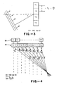
- Figure 4 is a functional block diagram of a phased array of transducer elements in accordance with the invention and illustrating different path lengths of a reflected ultrasonic wave.
- Figure 1 is a functional block diagram of a phased array of transducer elements shown generally at 10 in which electrical signals from each transducer element is passed through a delay line as shown generally at 12 and then summed at 14.
- a wave received by the element T N must be delayed relative to the signal generated by transducer element T1 at the opposite end of the array due to the shorter reflection path from the point 16 to element T N as opposed to the longer distance from the point 16 to the element T1.
- Such a system is described in U. S. Patent No. 4,387,597, supra. As there described, such scanners have been difficult and costly to implement because of the many delay lines required.
- FIG. 2 is a functional block diagram of a phased array of transducer elements and circuitry for steering the transducer elements in accordance with an embodiment of the present invention.
- the transducer elements are grouped with a plurality of adjacent transducer elements in each group, such as the four transducer elements T1 through T4.
- the electrical signals generated by each transducer element in the group are applied to mixers 22 where the signals are mixed with a signal, ⁇ t, which is selectively delayed in phase to compensate for differences in path length of the reflected wave from a point 24 to each of the transducer elements.
- the coherent outputs from the mixers 22 are then summed at 26 and then applied through a delay line 28.
- the other groups of transducer elements in the array 20 are frequency modulated with selective phase delay, summed, and then applied through other delay lines before a final summing of the delayed signals at 30.
- the number of delay lines 28 is a fraction of the total number of transducer elements, depending on the number of transducer elements in each group, as opposed to the equal number of delay elements from the transducer elements in the system of Figure 1.
- ⁇ n 2 ⁇ ⁇ [R max - ⁇ R2-2R( n ⁇ 2 ) cos (90- ⁇ ) + ( n ⁇ 2 )2 ⁇ 1 ⁇ 2 ]
- R max is the maximum distance of a transducer array group from a reflection point
- R is the average distance of a group of transducers from the reflection point.
- Figure 4 is a functional block diagram of the array of transducer elements and illustrates the amount of time delay required by the delay lines 28 in Figure 2.
- the lengths, 1, are shown from a focal point to the middle of each group of transducer elements and the angle, ⁇ , associated therewith. Since the length 11, is the longest pathlength for a reflected wave, the time delay of D1 is zero. Conversely, the shortest path length is L8 and consequently the delay of delay line D8 is the greatest and is given as follows: where c is the speed of sound in the medium being imaged.
Landscapes
- Engineering & Computer Science (AREA)
- Physics & Mathematics (AREA)
- Computer Networks & Wireless Communication (AREA)
- General Physics & Mathematics (AREA)
- Radar, Positioning & Navigation (AREA)
- Remote Sensing (AREA)
- Multimedia (AREA)
- Acoustics & Sound (AREA)
- Signal Processing (AREA)
- Investigating Or Analyzing Materials By The Use Of Ultrasonic Waves (AREA)
- Measurement Of Velocity Or Position Using Acoustic Or Ultrasonic Waves (AREA)
- Ultra Sonic Daignosis Equipment (AREA)
Claims (10)
- Verfahren zum selektiven Richten einer phasengesteuerten Array von Wandlerelementen in einem Ultraschall-Abbildungssystem, enthaltend die Schritte
Gruppieren von Wandlerelementen zur Bildung von mehreren Gruppen von Wandlerelementen,
Mischen jedes elektrischen Signals aus jeder Gruppe mit einem Modulationssignal einer festen Frequenz, wobei jedes Modulationssignal selektiv phasenverzögert ist für jedes elektrische Signal in jeder Gruppe in Abhängigkeit von dem Richtungswinkel eines Reflexionspunktes in einem abgebildeten Volumen, und
Summieren der gemischten elektrischen Signale für jede Gruppe,
gekennzeichnet durch:
selektives Phasenverzögern der summierten elektrischen Signale für jede Gruppe und
Summieren der selektiv zeitverzögerten summierten elektrischen Signale. - Verfahren nach Anspruch 1, wobei der Abstand von benachbarten Wandlerelementen eine halbe Wellenlänge einer gesendeten Ultraschallwelle ist, ϑ der Winkel eines Reflexionspunktes in einem abgebildeten Volumen ist und φ eine Einheit der Phasenverzögerung für benachbarte Wandlerelemente in einer Gruppe ist und

- Verfahren nach Anspruch 1, wobei die Frequenz der Modulationssignale gewählt ist zur Entwicklung einer Zwischenfrequenz zur Signalverarbeitung.
- Verfahren nach Anspruch 1, wobei die Frequenz der Modulationssignale zur Entwicklung eines Basisbandsignals zur Signalverarbeitung gewählt ist.
- Verfahren nach Anspruch 1, wobei die selektive Zeitverzögerung für Signale in jeder Gruppe durch die Differenz in der längsten Reflexionsbahn zu einer Gruppe von einem Reflexionspunkt und der Reflexionsbahn zu jeder Gruppe von dem Reflexionspunkt ermittelt wird.
- Einrichtung zum selektiven Richten einer phasengesteuerten Array von Wandlerelementen in einem Ultraschall- Abbildungssystem, enthaltend
mehrere Gruppen von benachbarten Wandlerelementen,
Mittel zum Mischen jedes elektrischen Signals aus jeder Gruppe von Wandlern mit einem Modulationssignal einer festen Frequenz, wobei jedes Modulationssignal selektiv phasenverzögert ist für jedes elektrisches Signal in der Gruppe in Abhängigkeit von dem Richtungswinkel eines Reflexionspunktes in einem abgebildeten Volumen, und
Mittel zum Summieren der gemischten elektrischen Signale für jede Gruppe,
gekennzeichnet durch:
Mittel zum selektiven Zeitverzögern der summierten elektrischen Signale für alle Gruppen und Mittel zum Summieren der selektiv zeitverzögerten summierten elektrischen Signale. - Einrichtung nach Anspruch 6, wobei der Abstand von benachbarten Wandlerelementen eine halbe Wellenlänge einer gesendeten Ultraschallwelle ist, ϑ der Winkel von einem Reflexionspunkt in dem abgebildeten Volumen ist und φ die Einheit der Phasenverzögerung für benachbarte Wandlerelemente in einer Gruppe ist, wobei

- Einrichtung nach Anspruch 6, wobei die Mittel zum Mischen jedes elektrischen Signals eine Zwischenfrequenz für eine anschließende Signalverarbeitung entwickeln.
- Einrichtung nach Anspruch 6, wobei die Mittel zum Mischen der elektrischen Signale ein Basisbandsignal zur anschließenden Verarbeitung entwickeln.
- Einrichtung nach Anspruch 6, wobei die selektive Zeitverzögerung für die Zeitverzögerungsmittel ermittelt ist durch die Differenz in der längsten Reflexionsbahn von einem Reflexionspunkt zu einer Gruppe und der Reflexionsbahn zu jeder speziellen Gruppe.
Applications Claiming Priority (2)
| Application Number | Priority Date | Filing Date | Title |
|---|---|---|---|
| US06/794,093 US4662223A (en) | 1985-10-31 | 1985-10-31 | Method and means for steering phased array scanner in ultrasound imaging system |
| US794093 | 1985-10-31 |
Publications (2)
| Publication Number | Publication Date |
|---|---|
| EP0223080A1 EP0223080A1 (de) | 1987-05-27 |
| EP0223080B1 true EP0223080B1 (de) | 1991-12-27 |
Family
ID=25161686
Family Applications (1)
| Application Number | Title | Priority Date | Filing Date |
|---|---|---|---|
| EP86114438A Expired - Lifetime EP0223080B1 (de) | 1985-10-31 | 1986-10-17 | Verfahren und Vorrichtung zum Steuern eines phasengesteuerten Gruppenstrahlerabtasters in einem Ultraschallabbildungssystem |
Country Status (6)
| Country | Link |
|---|---|
| US (1) | US4662223A (de) |
| EP (1) | EP0223080B1 (de) |
| JP (1) | JPS62112081A (de) |
| KR (1) | KR870004608A (de) |
| DE (1) | DE3683135D1 (de) |
| IL (1) | IL79846A0 (de) |
Families Citing this family (36)
| Publication number | Priority date | Publication date | Assignee | Title |
|---|---|---|---|---|
| JPS6070381A (ja) * | 1983-09-28 | 1985-04-22 | Toshiba Corp | 超音波映像化装置 |
| US4827229A (en) * | 1987-06-30 | 1989-05-02 | Litton Systems, Inc. | Broad band bulk acoustic wave spectrum analyzer/channelizer |
| US4801941A (en) * | 1987-06-30 | 1989-01-31 | Litton Systems, Inc. | Angle of arrival processor using bulk acoustic waves |
| US4835689A (en) * | 1987-09-21 | 1989-05-30 | General Electric Company | Adaptive coherent energy beam formation using phase conjugation |
| US4886069A (en) * | 1987-12-21 | 1989-12-12 | General Electric Company | Method of, and apparatus for, obtaining a plurality of different return energy imaging beams responsive to a single excitation event |
| FR2631707B1 (fr) * | 1988-05-20 | 1991-11-29 | Labo Electronique Physique | Echographe ultrasonore a coherence de phase controlable |
| US5229933A (en) * | 1989-11-28 | 1993-07-20 | Hewlett-Packard Company | 2-d phased array ultrasound imaging system with distributed phasing |
| US5271276A (en) * | 1990-11-28 | 1993-12-21 | Hitachi, Ltd. | Phase regulating apparatus of ultrasonic measuring devices |
| JPH04291185A (ja) * | 1991-03-20 | 1992-10-15 | Fujitsu Ltd | 超音波受信ビームフォーマ |
| US5121364A (en) * | 1991-08-07 | 1992-06-09 | General Electric Company | Time frequency control filter for an ultrasonic imaging system |
| US5142649A (en) * | 1991-08-07 | 1992-08-25 | General Electric Company | Ultrasonic imaging system with multiple, dynamically focused transmit beams |
| US5235982A (en) * | 1991-09-30 | 1993-08-17 | General Electric Company | Dynamic transmit focusing of a steered ultrasonic beam |
| US5291892A (en) * | 1991-11-04 | 1994-03-08 | General Electric Company | Ultrasonic flow imaging |
| US5172343A (en) * | 1991-12-06 | 1992-12-15 | General Electric Company | Aberration correction using beam data from a phased array ultrasonic scanner |
| US5230340A (en) * | 1992-04-13 | 1993-07-27 | General Electric Company | Ultrasound imaging system with improved dynamic focusing |
| US5318033A (en) * | 1992-04-17 | 1994-06-07 | Hewlett-Packard Company | Method and apparatus for increasing the frame rate and resolution of a phased array imaging system |
| US5251186A (en) * | 1992-10-06 | 1993-10-05 | The United States Of America As Represented By The Secretary Of The Navy | Preprocessor and adaptive beamformer for linear-frequency modulation active signals |
| DE4414081C1 (de) * | 1994-04-22 | 1995-10-12 | Sonident Anstalt | Verfahren und Vorrichtung zum Abtasten eines Ultraschallfeldes |
| US5793701A (en) * | 1995-04-07 | 1998-08-11 | Acuson Corporation | Method and apparatus for coherent image formation |
| US5928152A (en) * | 1994-08-05 | 1999-07-27 | Acuson Corporation | Method and apparatus for a baseband processor of a receive beamformer system |
| US6029116A (en) * | 1994-08-05 | 2000-02-22 | Acuson Corporation | Method and apparatus for a baseband processor of a receive beamformer system |
| US5685308A (en) * | 1994-08-05 | 1997-11-11 | Acuson Corporation | Method and apparatus for receive beamformer system |
| US5677491A (en) * | 1994-08-08 | 1997-10-14 | Diasonics Ultrasound, Inc. | Sparse two-dimensional transducer array |
| US5573001A (en) * | 1995-09-08 | 1996-11-12 | Acuson Corporation | Ultrasonic receive beamformer with phased sub-arrays |
| US5991239A (en) * | 1996-05-08 | 1999-11-23 | Mayo Foundation For Medical Education And Research | Confocal acoustic force generator |
| US6108275A (en) * | 1997-12-16 | 2000-08-22 | The Penn State Research Foundation | Phased beam transducer |
| US6013032A (en) * | 1998-03-13 | 2000-01-11 | Hewlett-Packard Company | Beamforming methods and apparatus for three-dimensional ultrasound imaging using two-dimensional transducer array |
| US5997479A (en) * | 1998-05-28 | 1999-12-07 | Hewlett-Packard Company | Phased array acoustic systems with intra-group processors |
| GB2414800B (en) * | 2000-01-27 | 2006-05-31 | Thomson Marconi Sonar Ltd | Sonar receiver with low side lobes |
| WO2002054379A2 (en) * | 2001-01-05 | 2002-07-11 | Angelsen Bjoern A J | Annular array |
| US6572547B2 (en) | 2001-07-31 | 2003-06-03 | Koninklijke Philips Electronics N.V. | Transesophageal and transnasal, transesophageal ultrasound imaging systems |
| USRE45759E1 (en) * | 2001-07-31 | 2015-10-20 | Koninklijke Philips N.V. | Transesophageal and transnasal, transesophageal ultrasound imaging systems |
| US7635334B2 (en) * | 2004-04-28 | 2009-12-22 | Siemens Medical Solutions Usa, Inc. | Dynamic sub-array mapping systems and methods for ultrasound imaging |
| JP5419727B2 (ja) * | 2010-01-22 | 2014-02-19 | キヤノン株式会社 | 画像形成方法及び音響波測定装置 |
| KR20150041471A (ko) * | 2013-10-08 | 2015-04-16 | 삼성전자주식회사 | 빔포밍 장치 및 빔포밍 방법 |
| US10613205B2 (en) | 2014-10-06 | 2020-04-07 | Analog Devices, Inc. | Systems and methods for ultrasound beamforming |
Citations (1)
| Publication number | Priority date | Publication date | Assignee | Title |
|---|---|---|---|---|
| US4387597A (en) * | 1980-12-08 | 1983-06-14 | Advanced Technology Laboratories, Inc. | Beamforming apparatus and method for ultrasonic imaging systems |
Family Cites Families (15)
| Publication number | Priority date | Publication date | Assignee | Title |
|---|---|---|---|---|
| CA1091054A (en) * | 1976-05-13 | 1980-12-09 | Frank R. Burgener, Jr. | One-way clutch for auger agitator |
| FR2399661A1 (fr) * | 1977-08-05 | 1979-03-02 | Anvar | Perfectionnements aux dispositifs de formation d'images ultrasonores en echographie b |
| JPS5438693A (en) * | 1977-09-02 | 1979-03-23 | Hitachi Medical Corp | Ultrasonic wave diagnosing device |
| US4140022B1 (en) * | 1977-12-20 | 1995-05-16 | Hewlett Packard Co | Acoustic imaging apparatus |
| US4180791A (en) * | 1978-03-09 | 1979-12-25 | General Electric Company | Simplified sector scan ultrasonic imaging system |
| US4154113A (en) * | 1978-05-24 | 1979-05-15 | General Electric Company | Ultrasonic imaging system |
| US4155260A (en) * | 1978-05-24 | 1979-05-22 | General Electric Company | Ultrasonic imaging system |
| JPS5584154A (en) * | 1978-12-19 | 1980-06-25 | Matsushita Electric Industrial Co Ltd | Ultrasoniccwave diagnosis device |
| US4290127A (en) * | 1979-12-03 | 1981-09-15 | Raytheon Company | Beamformer with reduced sampling rate |
| JPS5817386A (ja) * | 1981-07-23 | 1983-02-01 | Furuno Electric Co Ltd | 多数チヤンネルパルスの位相制御回路 |
| JPS58157454A (ja) * | 1982-03-15 | 1983-09-19 | 株式会社東芝 | 超音波診断装置 |
| US4484477A (en) * | 1982-09-29 | 1984-11-27 | S R I International | Variable delay memory system |
| JPS60179676A (ja) * | 1983-08-01 | 1985-09-13 | Furuno Electric Co Ltd | 受波ビ−ムの指向方向制御装置 |
| US4598589A (en) * | 1984-07-17 | 1986-07-08 | General Electric Company | Method of CW doppler imaging using variably focused ultrasonic transducer array |
| JPS6089781A (ja) * | 1984-09-14 | 1985-05-20 | Hitachi Ltd | 受波装置 |
-
1985
- 1985-10-31 US US06/794,093 patent/US4662223A/en not_active Expired - Fee Related
-
1986
- 1986-08-26 IL IL79846A patent/IL79846A0/xx unknown
- 1986-10-17 DE DE8686114438T patent/DE3683135D1/de not_active Expired - Lifetime
- 1986-10-17 EP EP86114438A patent/EP0223080B1/de not_active Expired - Lifetime
- 1986-10-28 JP JP61254853A patent/JPS62112081A/ja active Pending
- 1986-10-30 KR KR860009118A patent/KR870004608A/ko not_active Ceased
Patent Citations (1)
| Publication number | Priority date | Publication date | Assignee | Title |
|---|---|---|---|---|
| US4387597A (en) * | 1980-12-08 | 1983-06-14 | Advanced Technology Laboratories, Inc. | Beamforming apparatus and method for ultrasonic imaging systems |
Also Published As
| Publication number | Publication date |
|---|---|
| EP0223080A1 (de) | 1987-05-27 |
| KR870004608A (ko) | 1987-05-11 |
| JPS62112081A (ja) | 1987-05-23 |
| DE3683135D1 (de) | 1992-02-06 |
| IL79846A0 (en) | 1986-11-30 |
| US4662223A (en) | 1987-05-05 |
Similar Documents
| Publication | Publication Date | Title |
|---|---|---|
| EP0223080B1 (de) | Verfahren und Vorrichtung zum Steuern eines phasengesteuerten Gruppenstrahlerabtasters in einem Ultraschallabbildungssystem | |
| US4886069A (en) | Method of, and apparatus for, obtaining a plurality of different return energy imaging beams responsive to a single excitation event | |
| US4835689A (en) | Adaptive coherent energy beam formation using phase conjugation | |
| US5123415A (en) | Ultrasonic imaging by radial scan of trapezoidal sector | |
| US4017859A (en) | Multi-path signal enhancing apparatus | |
| US4989143A (en) | Adaptive coherent energy beam formation using iterative phase conjugation | |
| US4829491A (en) | Phased-array equipment | |
| US4368643A (en) | Ultrasonic imaging by radial scan beams emanating from a hypothetical point located behind linear transducer array | |
| EP0642036B1 (de) | Ultraschall-Diagnosegerät | |
| US5510799A (en) | Method and apparatus for digital signal processing | |
| US4598589A (en) | Method of CW doppler imaging using variably focused ultrasonic transducer array | |
| US5684484A (en) | Method and apparatus for multi-channel digital reception and apparatus of ultrasonic diagnosis | |
| GB2293240A (en) | Ultrasound system | |
| US4961176A (en) | Ultrasonic probe | |
| US5596549A (en) | Side look sonar apparatus and method | |
| US4510586A (en) | Array system with high resolving power | |
| US4245333A (en) | Beamforming utilizing a surface acoustic wave device | |
| US5164628A (en) | Elastic surface wave convolva having wave width converting means and communication system using same | |
| US4244037A (en) | Two dimensional imaging using surface wave acoustic devices | |
| US6307506B1 (en) | Method and apparatus for enhancing the directional transmission and reception of information | |
| US4552020A (en) | Apparatus for the scanning of objects by means of ultrasound echography | |
| GB2197952A (en) | Acoustic echo-sounding system | |
| CA1218121A (en) | Signal processing system and method | |
| JPH0693894B2 (ja) | 超音波診断装置 | |
| US4627290A (en) | Method and apparatus for detecting acoustic homogeneity of object |
Legal Events
| Date | Code | Title | Description |
|---|---|---|---|
| PUAI | Public reference made under article 153(3) epc to a published international application that has entered the european phase |
Free format text: ORIGINAL CODE: 0009012 |
|
| AK | Designated contracting states |
Kind code of ref document: A1 Designated state(s): DE FR GB NL |
|
| 17P | Request for examination filed |
Effective date: 19871028 |
|
| 17Q | First examination report despatched |
Effective date: 19900116 |
|
| GRAA | (expected) grant |
Free format text: ORIGINAL CODE: 0009210 |
|
| AK | Designated contracting states |
Kind code of ref document: B1 Designated state(s): DE FR GB NL |
|
| ET | Fr: translation filed | ||
| REF | Corresponds to: |
Ref document number: 3683135 Country of ref document: DE Date of ref document: 19920206 |
|
| PGFP | Annual fee paid to national office [announced via postgrant information from national office to epo] |
Ref country code: FR Payment date: 19920913 Year of fee payment: 7 |
|
| PGFP | Annual fee paid to national office [announced via postgrant information from national office to epo] |
Ref country code: DE Payment date: 19920914 Year of fee payment: 7 |
|
| PGFP | Annual fee paid to national office [announced via postgrant information from national office to epo] |
Ref country code: GB Payment date: 19920922 Year of fee payment: 7 |
|
| REG | Reference to a national code |
Ref country code: GB Ref legal event code: 746 |
|
| PLBE | No opposition filed within time limit |
Free format text: ORIGINAL CODE: 0009261 |
|
| STAA | Information on the status of an ep patent application or granted ep patent |
Free format text: STATUS: NO OPPOSITION FILED WITHIN TIME LIMIT |
|
| PGFP | Annual fee paid to national office [announced via postgrant information from national office to epo] |
Ref country code: NL Payment date: 19921031 Year of fee payment: 7 |
|
| 26N | No opposition filed | ||
| REG | Reference to a national code |
Ref country code: FR Ref legal event code: DL |
|
| PG25 | Lapsed in a contracting state [announced via postgrant information from national office to epo] |
Ref country code: GB Effective date: 19931017 |
|
| PG25 | Lapsed in a contracting state [announced via postgrant information from national office to epo] |
Ref country code: NL Effective date: 19940501 |
|
| GBPC | Gb: european patent ceased through non-payment of renewal fee |
Effective date: 19931017 |
|
| NLV4 | Nl: lapsed or anulled due to non-payment of the annual fee | ||
| PG25 | Lapsed in a contracting state [announced via postgrant information from national office to epo] |
Ref country code: FR Effective date: 19940630 |
|
| PG25 | Lapsed in a contracting state [announced via postgrant information from national office to epo] |
Ref country code: DE Effective date: 19940701 |
|
| REG | Reference to a national code |
Ref country code: FR Ref legal event code: ST |