EP0223312A2 - Verfahren zum Umhüllen von Gegenständen, Mittel zu seiner Ausführung und Erzeugnis - Google Patents
Verfahren zum Umhüllen von Gegenständen, Mittel zu seiner Ausführung und Erzeugnis Download PDFInfo
- Publication number
- EP0223312A2 EP0223312A2 EP86202035A EP86202035A EP0223312A2 EP 0223312 A2 EP0223312 A2 EP 0223312A2 EP 86202035 A EP86202035 A EP 86202035A EP 86202035 A EP86202035 A EP 86202035A EP 0223312 A2 EP0223312 A2 EP 0223312A2
- Authority
- EP
- European Patent Office
- Prior art keywords
- tension
- thread
- wire
- margin
- plate
- Prior art date
- Legal status (The legal status is an assumption and is not a legal conclusion. Google has not performed a legal analysis and makes no representation as to the accuracy of the status listed.)
- Granted
Links
- 238000000034 method Methods 0.000 title claims abstract description 59
- 230000008569 process Effects 0.000 claims abstract description 18
- 238000005520 cutting process Methods 0.000 claims abstract description 4
- 239000000463 material Substances 0.000 claims description 15
- 238000009958 sewing Methods 0.000 claims description 11
- 210000000078 claw Anatomy 0.000 claims description 10
- 230000000903 blocking effect Effects 0.000 claims description 7
- 230000007246 mechanism Effects 0.000 claims description 6
- 230000005540 biological transmission Effects 0.000 claims description 4
- 230000006835 compression Effects 0.000 claims description 4
- 238000007906 compression Methods 0.000 claims description 4
- 230000000717 retained effect Effects 0.000 claims description 4
- 239000004753 textile Substances 0.000 claims description 4
- 239000002023 wood Substances 0.000 claims description 4
- 208000005189 Embolism Diseases 0.000 claims description 3
- 230000000694 effects Effects 0.000 claims description 3
- 238000011144 upstream manufacturing Methods 0.000 claims description 2
- 230000000740 bleeding effect Effects 0.000 claims 2
- 230000000149 penetrating effect Effects 0.000 claims 1
- 239000004744 fabric Substances 0.000 description 29
- 239000002184 metal Substances 0.000 description 7
- 230000008901 benefit Effects 0.000 description 4
- 239000006260 foam Substances 0.000 description 4
- 230000009471 action Effects 0.000 description 3
- 238000004519 manufacturing process Methods 0.000 description 3
- 238000009964 serging Methods 0.000 description 3
- 238000000465 moulding Methods 0.000 description 2
- 230000002093 peripheral effect Effects 0.000 description 2
- 229920000914 Metallic fiber Polymers 0.000 description 1
- 238000009825 accumulation Methods 0.000 description 1
- YFXPPSKYMBTNAV-UHFFFAOYSA-N bensultap Chemical compound C=1C=CC=CC=1S(=O)(=O)SCC(N(C)C)CSS(=O)(=O)C1=CC=CC=C1 YFXPPSKYMBTNAV-UHFFFAOYSA-N 0.000 description 1
- 238000007796 conventional method Methods 0.000 description 1
- 230000001627 detrimental effect Effects 0.000 description 1
- 238000010586 diagram Methods 0.000 description 1
- 238000006073 displacement reaction Methods 0.000 description 1
- 238000009826 distribution Methods 0.000 description 1
- 239000013013 elastic material Substances 0.000 description 1
- 230000008030 elimination Effects 0.000 description 1
- 238000003379 elimination reaction Methods 0.000 description 1
- 238000005304 joining Methods 0.000 description 1
- 230000004048 modification Effects 0.000 description 1
- 238000012986 modification Methods 0.000 description 1
- 239000002994 raw material Substances 0.000 description 1
- 210000001519 tissue Anatomy 0.000 description 1
- 230000037303 wrinkles Effects 0.000 description 1
Images


Classifications
-
- A—HUMAN NECESSITIES
- A47—FURNITURE; DOMESTIC ARTICLES OR APPLIANCES; COFFEE MILLS; SPICE MILLS; SUCTION CLEANERS IN GENERAL
- A47C—CHAIRS; SOFAS; BEDS
- A47C31/00—Details or accessories for chairs, beds, or the like, not provided for in other groups of this subclass, e.g. upholstery fasteners, mattress protectors, stretching devices for mattress nets
- A47C31/02—Upholstery attaching means
- A47C31/023—Upholstery attaching means connecting upholstery to frames, e.g. by hooks, clips, snap fasteners, clamping means or the like
-
- B—PERFORMING OPERATIONS; TRANSPORTING
- B68—SADDLERY; UPHOLSTERY
- B68G—METHODS, EQUIPMENT, OR MACHINES FOR USE IN UPHOLSTERING; UPHOLSTERY NOT OTHERWISE PROVIDED FOR
- B68G7/00—Making upholstery
- B68G7/05—Covering or enveloping cores of pads
-
- D—TEXTILES; PAPER
- D05—SEWING; EMBROIDERING; TUFTING
- D05B—SEWING
- D05B1/00—General types of sewing apparatus or machines without mechanism for lateral movement of the needle or the work or both
- D05B1/08—General types of sewing apparatus or machines without mechanism for lateral movement of the needle or the work or both for making multi-thread seams
- D05B1/18—Seams for protecting or securing edges
- D05B1/20—Overedge seams
-
- D—TEXTILES; PAPER
- D05—SEWING; EMBROIDERING; TUFTING
- D05B—SEWING
- D05B29/00—Pressers; Presser feet
- D05B29/06—Presser feet
-
- D—TEXTILES; PAPER
- D05—SEWING; EMBROIDERING; TUFTING
- D05D—INDEXING SCHEME ASSOCIATED WITH SUBCLASSES D05B AND D05C, RELATING TO SEWING, EMBROIDERING AND TUFTING
- D05D2303/00—Applied objects or articles
- D05D2303/08—Cordage
-
- Y—GENERAL TAGGING OF NEW TECHNOLOGICAL DEVELOPMENTS; GENERAL TAGGING OF CROSS-SECTIONAL TECHNOLOGIES SPANNING OVER SEVERAL SECTIONS OF THE IPC; TECHNICAL SUBJECTS COVERED BY FORMER USPC CROSS-REFERENCE ART COLLECTIONS [XRACs] AND DIGESTS
- Y10—TECHNICAL SUBJECTS COVERED BY FORMER USPC
- Y10T—TECHNICAL SUBJECTS COVERED BY FORMER US CLASSIFICATION
- Y10T29/00—Metal working
- Y10T29/48—Upholstered article making
- Y10T29/486—Cover stretching
Definitions
- the invention relates to a method of pleating a piece of flexible material, such as a textile piece, and its application to the covering of objects by means of flexible covers, in particular seat upholstery called upon to constitute the backrest, the seat or the armrests of a seat. It extends to the products obtained by implementing said process, as well as to means specially designed or modified to allow this implementation: modified sewing machine, automated dressing press, manual instrument to facilitate implementation of the process.
- the seat covers are generally composed of a rigid support of appropriate shape and an elastic layer, in particular of foam, held on the front face of this support by a cover.
- the rigid support is generally made of wood or plastic (or similar material) but can also be metallic.
- the covers are currently made from pieces of fabric which are cut to the shape of the fillings, with a very wide margin around the edge.
- This margin makes it possible to grasp each cover by its edges, to crease it around the periphery of the lining and to exert a traction ensuring the positioning of said cover around its lining; said margin is then fixed on the rigid support, either on the back thereof, or on its periphery.
- this fixing is usually ensured by stapling the fabric to the support.
- this fixing is provided by a batten which is attached to the edge of the lining to pinch the margin of the fabric.
- This dressing process has serious flaws. Firstly, it requires a large workforce to perform the manual operation of fitting the cover by successive pulls, and the operation of fixing the latter by stapling or using battens. In the case of a metal support, these operations are not only long, but still delicate and require great skill.
- the large width of the margins required around the periphery of each piece of fabric results in significant losses of material compared to that strictly necessary for dressing the linings; very often these margins must be overcut to remove the floating strip of fabric, and this operation increases labor costs, while it entails risks of fraying of the edges of fabric, detrimental to the finished appearance of the product. .
- the folds of the cover around the periphery of the filling are often distributed irregularly and it is impossible after fixing to modify them to improve the presentation of the finished product.
- the cover is fixed inside a groove formed on the periphery of the rigid support.
- the fixing is ensured by stapling by means of a fine-pointed pistol and this operation is long and costly in terms of labor.
- An object of the present invention is to alleviate the above-mentioned drawbacks and to provide a method of covering objects allowing considerable savings in labor.
- Another objective is to allow significant savings in raw materials.
- Another objective is to make it possible to make a finished product benefiting from improved appearance qualities.
- the invention proposes to indicate an improved method of pleating a piece of flexible material, in particular textile, a method applicable in the above-mentioned context of the dressing of objects or in any other area.
- said pleating process is characterized in that it consists of a combination: stitching at the edge of the workpiece at least one auxiliary thread arranged to preserve a passage extending along said edge, setting up a tension wire in said passage so that this wire can slide inside and along this passage with protruding lengths at its two ends, and to exert on the two ends of the tensioning wire pulls in opposite directions tending to shorten the length of thread engaged in the aforementioned passage and to tighten the material of the part.
- the auxiliary threads are stitched so as to form an overlock on the edge of the piece, and the tension thread is placed continuously, simultaneously with the stitching, as said stitching.
- the tension thread and the auxiliary threads which guide and hold it can be placed directly on the piece to be pleated or, on the contrary, be arranged on an auxiliary tape which is then fixed, in particular by simple sewing, at the edge of the piece to be wrinkle.
- the process of the invention has significant advantages over the pleating processes used in the clothing sector; in fact, the pleating is carried out in this sector by means of a hem in which the tensioning thread is threaded.
- this hem which consists in folding and folding the edge of the fabric and in sewing the whole, is difficult in the nonlinear parts and, in practice, is not possible in the parts with strong curvatures without jamming the tension wire (especially in the corners).
- a hem necessarily involves two superimposed thicknesses and sometimes three, while the method of the invention makes it possible to pleat while keeping a single thickness at the edge of the textile piece.
- the method of the invention also has the advantages mentioned above compared to another pleating technique generally used for pleating curtains (this technique consists in equipping the edge of the piece of fabric with a braid pleat, composed of a band crossed right through by a narrower ribbon).
- the invention extends to a sewing machine modified to allow the implementation of the previously defined process.
- This machine is of the well known type, comprising a crowbar, at least one needle, at least one hook, means for driving these members and means for supplying auxiliary threads, with a view to making stitches. overlock; according to the present invention, it is equipped with means for supplying tension thread, means for guiding said thread towards the presser foot and a guide tunnel formed longitudinally in the presser foot and opening under it. ci, said tunnel being transversely positioned relative to the presser foot, needle and hooks, so as to guide the tension thread at an intermediate level between the stitching line and the overlock hooking line.
- the tension thread is thus brought to unwind continuously, and is guided towards the presser foot to align it at the edge of the workpiece, the overlock being produced above and on either side of it.
- the invention extends to an instrument intended to facilitate the execution of the pulling operation on the ends of the tension thread.
- This instrument is characterized in that it comprises a support, two rotary studs mounted on said support, means for wedging wire on each stud, a manual member for rotating entrainment and a transmission mechanism interposed between said member. entralmentation and said rotary studs and adapted to ensure a rotation in the opposite direction thereof from a rotation of said manual member.
- the invention also extends, as such, to a ribbon capable of constituting an auxiliary for the implementation of the pleating method defined above, this ribbon being characterized in that it comprises a tension wire running along of the latter, this tension wire being retained by auxiliary threads stitched onto said strip so as to allow longitudinal sliding of said tension thread.
- This process is applicable, as well in the case of a cover whose border must be positioned on the back of the object opposite its rear face, as in a cover whose border must be inserted in a groove made on the periphery of the object.
- the margin provided with the tension thread is folded back towards the rear face of the object, then the thread is tightened in the vicinity of said rear face during the pulling operation.
- the tension thread is positioned so as to come opposite the groove after folding the margin and is tightened to fit into said groove.
- the margin can be provided at the width strictly necessary since it no longer has to be grasped to pull on the fabric and since it no longer serves to fix the fabric on the object. At on the contrary, it is the ends of the tension thread which are pulled and the fabric is held by the tightening of the latter behind or around the object. It is thus possible to save material by cutting the parts more strictly. In addition, no excess is no longer necessary and the edge of the fabric provided with the overlock has a perfect appearance which contributes to giving the finished product a quality appearance. In addition, the cover is not blocked along the perimeter of the object as it is when it is stapled, fixed by strip, glued or welded. After blocking the ends of the tension thread, the operator can, if necessary, distribute the folds by sliding the margin along the tension thread in the circumferential direction.
- This dressing process according to the invention can be applied in a particularly profitable manner to the manufacture of seat upholstery composed of a rigid support and an elastic layer (foam or other). It conditions considerable savings in labor. It should also be noted in this case that the cutting of the piece of fabric can be very easily adapted as a function of the contour of the lining to obtain, after tensioning, a desired final shape.
- the ends of the tension wire can be blocked by any means and in particular by a knot joining them.
- these ends can be stapled to the back of the trim or in the groove around its periphery.
- the tension wire can be of any type suitable for the application.
- this wire can be an electrically conductive wire whose protruding planned end is fixed to a metal part of the seat to allow elimination of electrostatic charges.
- the rigid lining support is preferably manufactured by providing on its rear face at least one lug in the vicinity of each angle: the tension wire is tightened so as to bear against these lugs in order to better distribute the tightening effect and limit it at the angles.
- the lining covering process defined above can in particular be implemented on a press of the type comprising a plate, a movable compression plate located opposite said plate, means of displacement of said plate making it possible to separate it or to bring it closer to the plate, and a form of holding the lining, carried by the plate and having raised edges.
- said press is equipped, on two sides of the plate and in the vicinity thereof, with two grippers for gripping the ends of the tension wire, said grippers being located opposite one of the other and mounted on jacks capable of bringing them closer or apart in a plane substantially parallel to that of the plate, in order to exert traction on said ends of the tension wire.
- Such a press makes it possible to dress the seat upholstery in remarkable conditions of economy on labor costs.
- the present invention extends, as such, to the seat upholstery produced, comprising a rigid support, an elastic layer, a flexible cover covering one side of the upholstery and having a margin folded over the periphery of this face or towards the opposite face, and characterized in that said cover is held by a tension thread held by auxiliary threads stitched along the aforementioned margin, said tension thread being stretched and blocked so as to crease said margin and tighten it on the around the trim or towards the back.
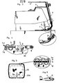
- the machine is provided with a coil for supplying an additional wire, known as tension wire 5, of larger diameter than the auxiliary wires 4 (in particular the coil for supplying itself of the conventional type. , which was not shown).
- tension wire 5 an additional wire, known as tension wire 5, of larger diameter than the auxiliary wires 4 (in particular the coil for supplying itself of the conventional type. , which was not shown).
- a rigid descending tube 6 is fixed to the front of the machine by a tab 7. This tube is arranged to guide the tension wire coming from the supply reel to the vicinity of presser foot 1, opposite from the upstream part of it.
- a flexible tube 8 of smaller diameter than the previous one is secured to the presser foot 1 by a holding part 9, so that one of its ends penetrates into the rigid tube 6.
- this flexible tube 8 is located opposite a tunnel 10 which is formed longitudinally in the presser foot so as to open below it.
- the flexible tube 8 thus forms a continuous passage between the rigid tube 6 and the tunnel 10, and its flexibility allows it to lend itself to the movements of the crowbar.
- the tunnel 10 is formed by a notch formed under the crowbar at the edge thereof; this notch is laterally closed by a square-shaped piece 11 fixed to the presser foot using a screw 12.
- the tunnel is thus transversely positioned relative to the presser foot, needle and hooks, so as to guide the tension thread 5 at an intermediate level between the stitching line Pq and the hooking line Pa of the overlock.
- the tension thread 5 unrolls continuously and is guided to align with the edge of the piece of fabric (referenced 25 in these figures), so that the overlock is made above the thread 5 and traps it in the longitudinal passage -P- preserved between the stitching line Pq and attachment line Pa. In this passage, the tension thread 5 remains free to slide longitudinally. It should be noted that no difficulty is encountered at the angles: it suffices to turn the piece of fabric in the usual way with respect to the machine.
- the piece of fabric can then be pleated by pulling in opposite directions over these lengths, in order to shorten the length engaged in the aforementioned passage.
- the piece of fabric is directly equipped with the tensioning thread 5, by stitching the auxiliary threads directly into the material thereof, with said tensioning thread being placed simultaneously.
- auxiliary ribbon 13 as shown in FIG. 7.
- This ribbon comprises at the edge a tension wire running along this one ; this tension wire is retained as previously by auxiliary threads stitched by means of the machine described above.
- ribbons such as 13 can be made available to users in order to avoid them having to equip themselves with a modified overlock machine: a simple traditional sewing machine is then enough to stitch the ribbon at the edge of the affected piece of fabric.
- Said press comprises a frame 14 which carries a horizontal plate 15, in the circular example.
- This plate is mounted on pivoting means such as a ball stop 16, allowing its rotation about a central axis perpendicular to its plane (in the example vertical axis).
- a mobile compression plate 17 which is carried by a jack 18 so that it can be moved vertically opposite the plate; in the same way as the plate, pivoting means such as ball stop 27 are inserted to allow the plate to rotate around the same vertical axis as the plate.
- each claw 19 is, in the example, of the known type comprising a blocking plate 19a to front toothed edge, articulated in a frame 19b: it is thus able to block one end of wire which has been engaged in said claw as shown in the detail in FIG. 8.
- the two claws 19 are located opposite one another and mounted on double-acting cylinders 20 capable of bringing them closer or apart in a plane substantially parallel to that of the plate.
- These jacks are preferably fixed on supports 21 making it possible to adjust the position depending on the type of trim to be dressed.
- the cylinders 20, in the example of a pneumatic nature, are controlled synchronously by means of a pedal 22.
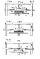
- FIGS 9a to 9e illustrate the process implemented by means of said covering press.
- a holding form 23 is placed in the center of the plate 15; it has raised edges 23a and its shape is adapted to that of the lining 24 to be dressed.
- This lining 24 is composed of a rigid support 24a and an elastic layer of foam 24b. Its cover referenced 25 is formed by a piece of fabric of the type of that of FIG. 5. Said piece previously cut to the shape of the lining with an additional margin 25a is therefore provided with the tension thread 5 at the edge of this margin.
- the piece of fabric 25, the layer of foam 24b and the rigid support 24a are superimposed in the shape 23 as illustrated in FIG. 9a, the margin 25a of the piece being raised by the edges 23a of the shape.
- the operator turns the plate 15 to place the two ends of the tension wire on the side of the claws 19.
- the plate 17 is then lowered by the action of the jack 18, until the elastic layer 24b is compressed (FIG. 9b).
- the claws 19 are then brought closer to each other by the action of their pneumatic cylinder 20 (FIG. 9c).
- the operator crosses the ends of the tension thread to hang each of them on the opposite claw.
- the claws 19 are then moved apart by the action of the jacks 20 (FIG. 9d). During their movement, they exert on the ends 5a, 5b of the pulls which tighten and fold the margin 25a, which comes to fall back against the rear face of the rigid support. Excellent regularity of the folds is obtained by subjecting the plate 15 to small rotational movements in one direction and the other (arrow R in FIG. 5d: the ball thrusts 16 and 27 allow this rotation in the compression position).
- the ends of the tension wire are then blocked, for example by stapling by means of a staple 26, on the back of the rigid support when this support is made of wood or the like (FIG. 9e). These ends can then be cut in the vicinity of the clip 26.
- the method described above allows savings in labor which can be estimated at around 50% compared to the conventional method of pulling the cover manually behind the rigid support, then stapling it over the whole around.
- the tension thread 5 can be of any type: thread, synthetic, natural or, if appropriate, metallic thread. In the latter case, a protruding length can be left waiting to be fixed later on a metal part of the seat such as its foot: the invention thus provides a simple means to avoid the accumulation of electrostatic charges on the seat.
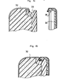
- Figure 11 shows in section a lining similar to the previous one, but in which the rigid support 28 is provided on edge with a groove 29.
- the cover is made so that its tension wire comes to be positioned opposite this groove after folding of the margin. During the pulls on its ends, this tension wire is inserted into said groove and comes to tighten therein.
- the ends can be locked by any means and in particular by a staple if the support is made of wood or the like.
- FIG. 12 represents, in partial perspective, another variant of the lining, wherein the rigid support is previously provided, during its manufacture, with a lug 30, projecting on its rear face, in the vicinity of each angle.
- This pin can be added by nailing, screwing ... in the case of a wooden support or come from a stamped cutout in the case of a metal support.
- the tension wire comes to bear against these lugs 30 (on the external side) so that the tightening effect is limited at the angles. This avoids too much tension on the piece of fabric in areas of very strong curvatures.
- FIG. 13 shows a possible method of blocking the ends of the tension wire in the case of a rigid metal support (where stapling is not possible).
- This support is previously provided during its manufacture with one (or more) lug 31 protruding at the location of the ends of the tension wire (stamped cut). At the point where the ends cross, the margin of the fabric is caused to pass under this lug and the latter is closed towards the support (arrow F) to wedge said ends after pulling.
- the method of the invention is particularly well suited for producing seat backs or seat covers coated on their two faces, as shown in FIGS. 14 and 15.
- a lining 32 of the preceding type is produced with a rigid support provided on its periphery with nesting means, in particular of a peripheral nesting molding 33; this lining is dressed by the method of the invention, in particular by tightening the tension thread of its cover in the molding 33.
- a plate 34 provided on its periphery with embolism means combined with those of the lining (in the example interlocking collar 35 of suitable shape and elasticity), is dressed in a similar manner by means of a cover.
- the tension wire can be tightened on the rear face of the embellishment flange.
- the lining 32 and the plate 34 are then presented back to back so that their dressed faces are in opposition, and are fitted and crimped by causing their embolism means to cooperate.
- the pull-up operation on the ends of the tension thread can be carried out in certain applications (dressing carried out without using a press, or any other pleating of fabric) by means of an instrument of the type represented in FIGS. 16, 17 and 18.
- This small accessory to be able to be held in hand comprises a support 36 which may be constituted by a flat-shaped casing. On this, are mounted two rotary studs 37, 38 arranged opposite one another. Each stud is provided with means for wedging one end of the wire.
- each pad is made of a slightly elastic material and these wedging means consist of a simple diametrical slot 39 formed in each pad.
- the two slots of the pads are initially arranged in parallel (or even slightly divergent) planes as illustrated in FIG. 16, with a cutaway on the facing halves, so as to be able to guide and perfectly block the ends of the wire in positions crossed.
- a manual member such as handle 40 makes it possible to drive these studs by means of a transmission mechanism housed in the support 36; this mechanism consists in the example of a pinion 41 secured to the handle, a pinion 42 secured to the pad 37 and arranged in direct engagement with the pinion 41, and a pinion 43 secured to the other pad 38 and arranged in engagement with an intermediate pinion 44.
- the two studs 37 and 38 thus rotate in opposite directions when the handle is rotated.
- the pinions are dimensioned so that these opposite rotations are performed at equal speed.
- a non-return member such as ratchet wheel 45 and ratchet 46, allows the rotation of the mechanism only in one direction in order to avoid a return after pulling on the ends of the wire.
Landscapes
- Engineering & Computer Science (AREA)
- Textile Engineering (AREA)
- Manufacturing & Machinery (AREA)
- Mechanical Engineering (AREA)
- Sewing Machines And Sewing (AREA)
- Road Signs Or Road Markings (AREA)
- Buffer Packaging (AREA)
- Treatment Of Fiber Materials (AREA)
- Chemical Or Physical Treatment Of Fibers (AREA)
- Laminated Bodies (AREA)
- Wrappers (AREA)
- Toys (AREA)
Priority Applications (1)
| Application Number | Priority Date | Filing Date | Title |
|---|---|---|---|
| AT86202035T ATE56760T1 (de) | 1985-11-20 | 1986-11-17 | Verfahren zum umhuellen von gegenstaenden, mittel zu seiner ausfuehrung und erzeugnis. |
Applications Claiming Priority (2)
| Application Number | Priority Date | Filing Date | Title |
|---|---|---|---|
| FR8517743 | 1985-11-20 | ||
| FR8517743A FR2590284B1 (fr) | 1985-11-20 | 1985-11-20 | Procede de plissage d'une piece souple, application a l'habillage d'objets, moyens de mise en oeuvre et produits obtenus |
Publications (3)
| Publication Number | Publication Date |
|---|---|
| EP0223312A2 true EP0223312A2 (de) | 1987-05-27 |
| EP0223312A3 EP0223312A3 (en) | 1989-08-23 |
| EP0223312B1 EP0223312B1 (de) | 1990-09-19 |
Family
ID=9325308
Family Applications (1)
| Application Number | Title | Priority Date | Filing Date |
|---|---|---|---|
| EP86202035A Expired - Lifetime EP0223312B1 (de) | 1985-11-20 | 1986-11-17 | Verfahren zum Umhüllen von Gegenständen, Mittel zu seiner Ausführung und Erzeugnis |
Country Status (7)
| Country | Link |
|---|---|
| US (1) | US4732097A (de) |
| EP (1) | EP0223312B1 (de) |
| AT (1) | ATE56760T1 (de) |
| DE (1) | DE3674343D1 (de) |
| ES (1) | ES2017629B3 (de) |
| FR (1) | FR2590284B1 (de) |
| GR (1) | GR3002537T3 (de) |
Cited By (2)
| Publication number | Priority date | Publication date | Assignee | Title |
|---|---|---|---|---|
| FR2766213A1 (fr) * | 1997-07-15 | 1999-01-22 | Christian Guilhem | Procede de couture et machine a coudre permettant de degager un fil de tension d'un passage forme par un point de couture |
| US7291236B2 (en) | 2002-05-29 | 2007-11-06 | Christian Guilhem | Method and machine for producing a seam which is not susceptible to coming undone |
Families Citing this family (20)
| Publication number | Priority date | Publication date | Assignee | Title |
|---|---|---|---|---|
| FR2634190B1 (fr) * | 1988-07-13 | 1992-04-17 | Guilhem Christian | Procede et dispositif pour le positionnement d'un objet en vue en particulier de son habillage au moyen d'une piece souple et/ou de son assemblage |
| US4986055A (en) * | 1990-02-16 | 1991-01-22 | Machine Design Systems, Inc. | Cushion compression machine for compressing a cushion and applying a cover to the cushion |
| US5189772A (en) * | 1991-01-14 | 1993-03-02 | Key Plastics Sales, Inc. | Method of upholstering |
| FR2678001B1 (fr) * | 1991-06-20 | 1993-09-17 | Guilhem Christian | Procede d'habillage d'objets au moyen d'une housse souple, moyen utilise lors de la mise en óoeuvre et produits obtenus. |
| US5187848A (en) * | 1991-10-22 | 1993-02-23 | Tachi-S Co. Ltd. | Method of assembling a seat back |
| FR2697826B1 (fr) * | 1992-11-06 | 1995-02-17 | Faure Bertrand Automobile | Coiffe et procédé pour recouvrir un coussin de siège de véhicule automobile. |
| AU6786994A (en) * | 1993-05-12 | 1994-12-12 | N.F.A. Corp. | Seat, upholstery attachment means, and upholstering method |
| US5529373A (en) * | 1994-06-27 | 1996-06-25 | Hon Industries Inc. | Apparatus and method for covering a chair form with fabric |
| FR2750087B1 (fr) * | 1996-06-19 | 1998-09-04 | Faure Bertrand Equipements Sa | Element de siege de vehicule comportant une coiffe tendue sur une armature metallique |
| US5935364A (en) * | 1996-10-02 | 1999-08-10 | Steelcase Inc. | Thermal forming upholstery process |
| US5768761A (en) | 1997-02-13 | 1998-06-23 | Milliken Research Corporation | Chair seat frame system |
| US5950553A (en) * | 1997-07-16 | 1999-09-14 | Lear Corporation | Method and apparatus for slidably retaining a drawstring cord within a trim cover material |
| JP4317607B2 (ja) * | 1998-12-14 | 2009-08-19 | 株式会社日立製作所 | 情報処理装置、耐タンパ処理装置 |
| DE19912398A1 (de) * | 1999-03-19 | 2000-09-28 | Rolf Voelkle | Verfahren zum Beziehen der Oberfläche eines Sitzmöbels sowie dadurch hergestellte Sitzfläche oder Lehnenfläche |
| US20080246296A1 (en) * | 2007-04-03 | 2008-10-09 | Gm Global Technology Operations, Inc. | Static-Reducing Vehicle Seat |
| US8453306B2 (en) * | 2008-07-16 | 2013-06-04 | L & P Property Management Company | Method for upholstering box springs |
| DE102018202390A1 (de) * | 2018-02-16 | 2019-08-22 | Bayerische Motoren Werke Aktiengesellschaft | Kraftfahrzeugsitz, hiermit ausgestattetes Kraftfahrzeug sowie Verfahren zum Einstellen einer Bezugsspannung des Kraftfahrzeugsitzes |
| US11589678B2 (en) | 2019-01-17 | 2023-02-28 | Hni Technologies Inc. | Chairs including flexible frames |
| IT202000005974A1 (it) * | 2020-03-20 | 2021-09-20 | Quarrata Forniture S R L | Macchina per applicare una fodera ad un supporto |
| IT202300016380A1 (it) * | 2023-08-02 | 2025-02-02 | Alessandro Marco Genta | Sistema di aggancio oggettivato per elementi di sellatura |
Family Cites Families (12)
| Publication number | Priority date | Publication date | Assignee | Title |
|---|---|---|---|---|
| DE136699C (de) * | 1901-01-23 | 1902-02-01 | ||
| DE564636C (de) * | 1932-11-21 | Saechsische Corsetschonerfabri | Elastische Kanteneinfassung fuer Bekleidungsstuecke | |
| BE569937A (de) * | ||||
| US726311A (en) * | 1901-10-02 | 1903-04-28 | Sophie Hessel | Thread-and-cord edge-finish for fabrics. |
| GB190624964A (en) * | 1906-11-06 | 1907-10-10 | William Buckler | Improvements in or relating to Knitted Garments. |
| GB190821028A (en) * | 1908-10-06 | 1909-11-08 | George Macbeth | Improvements in or connected with "Cash Registers." |
| FR553347A (fr) * | 1923-05-26 | 1923-05-22 | Procédé et dispositif pour emprisonner un fil sur une face d'un ouvrage, par une piqûre à la machine | |
| US1717075A (en) * | 1924-08-04 | 1929-06-11 | Union Special Machine Co | Hat sweat and process of making the same |
| CH175992A (de) * | 1934-04-13 | 1935-03-31 | Singer Mfg Co | Nähmaschinendrückerfuss. |
| US2212485A (en) * | 1937-08-14 | 1940-08-20 | Sure Fit Products Company | Slip cover construction for upholstered furniture |
| US2946069A (en) * | 1956-12-17 | 1960-07-26 | Jo An Shoe Mfg Co Inc | Method of manufacturing moccasins |
| US3424161A (en) * | 1966-02-25 | 1969-01-28 | Kendall & Co | Sewn diaper with non-raveling stitching |
-
1985
- 1985-11-20 FR FR8517743A patent/FR2590284B1/fr not_active Expired - Lifetime
-
1986
- 1986-11-17 EP EP86202035A patent/EP0223312B1/de not_active Expired - Lifetime
- 1986-11-17 DE DE8686202035T patent/DE3674343D1/de not_active Expired - Lifetime
- 1986-11-17 AT AT86202035T patent/ATE56760T1/de not_active IP Right Cessation
- 1986-11-17 ES ES86202035T patent/ES2017629B3/es not_active Expired - Lifetime
- 1986-11-18 US US06/932,178 patent/US4732097A/en not_active Expired - Lifetime
-
1990
- 1990-11-19 GR GR90400941T patent/GR3002537T3/el unknown
Cited By (4)
| Publication number | Priority date | Publication date | Assignee | Title |
|---|---|---|---|---|
| FR2766213A1 (fr) * | 1997-07-15 | 1999-01-22 | Christian Guilhem | Procede de couture et machine a coudre permettant de degager un fil de tension d'un passage forme par un point de couture |
| WO1999004079A1 (fr) * | 1997-07-15 | 1999-01-28 | Christian Guilhem | Procede de couture et machine a coudre permettant de degager un fil de tension d'un passage forme par un point de couture |
| US7291236B2 (en) | 2002-05-29 | 2007-11-06 | Christian Guilhem | Method and machine for producing a seam which is not susceptible to coming undone |
| US7857927B2 (en) | 2002-05-29 | 2010-12-28 | Christian Guilhem | Method and machine for producing a seam which is not susceptible to coming undone |
Also Published As
| Publication number | Publication date |
|---|---|
| ATE56760T1 (de) | 1990-10-15 |
| EP0223312B1 (de) | 1990-09-19 |
| US4732097A (en) | 1988-03-22 |
| GR3002537T3 (en) | 1993-01-25 |
| FR2590284A1 (fr) | 1987-05-22 |
| EP0223312A3 (en) | 1989-08-23 |
| ES2017629B3 (es) | 1991-03-01 |
| FR2590284B1 (fr) | 1996-07-12 |
| DE3674343D1 (de) | 1990-10-25 |
Similar Documents
| Publication | Publication Date | Title |
|---|---|---|
| EP0223312B1 (de) | Verfahren zum Umhüllen von Gegenständen, Mittel zu seiner Ausführung und Erzeugnis | |
| CA2070566C (fr) | Procede d'habillage d'objets au moyen d'une housse souple, moyen utilise lors de la mise en oeuvre et produits obtenus | |
| FR2631987A1 (fr) | Dispositif d'avance automatique pour une machine a coudre utilisee notamment dans la fabrication d'un siege de vehicule | |
| FR2878241A1 (fr) | Machine automatique pour la formation d'un noeud a l'aide d'une ficelle en extremite d'une gaine tubulaire en vue de l'obturer par constriction sous l'effet du serrage du noeud | |
| EP1000189B1 (de) | Nähverfahren und nähmaschine die das freimachen einer ziehschnur aus einer durch eine nähnaht geformte passage ermöglicht | |
| BE426458A (de) | ||
| FR2678649A1 (fr) | Machine a broder. | |
| FR2626201A1 (fr) | Support textile brode, procede de decoration d'un support textile et dispositif permettant la mise en oeuvre dudit procede | |
| EP0008986A1 (de) | Verfahren und Vorrichtung zum Beziehen eines Polsters mit einem Bezug | |
| FR2594303A1 (fr) | Procede de couture permettant de prevoir et de fixer des boucles fermees sur une zone d'une piece textile et installation de couture autorisant la mise en oeuvre dudit procede | |
| FR2791052A1 (fr) | Procede pour recouvrir la superficie d'un siege et surface d'assise ou de dossier ainsi fabriquee | |
| FR2474071A1 (fr) | Procede de fabrication des pompons, des moyens de mise en oeuvre de ce procede et les produits obtenus | |
| FR2677922A1 (fr) | Materiau composite pour la confection et la decoration et son procede d'obtention. | |
| FR2648326A1 (fr) | Parure de tete pour mariee | |
| FR2621789A1 (fr) | Sac et son procede de fabrication | |
| WO2016030622A1 (fr) | Procédé de réalisation d'une pièce ornementale à anneaux entrelacés | |
| EP0041905B1 (de) | Verfahren und Vorrichtung zur Befestigung durch Verklebung eines biegsamen und undurchlässigen Materials auf einem Lampenschirmgestell | |
| FR2853915A1 (fr) | Mecanisme d'avance automatise pour machine a coudre | |
| FR2638069A1 (fr) | Procede et dispositif pour realiser une bretelle de vetement telle qu'une bretelle de soutien-gorge | |
| FR2939378A1 (fr) | Procede et dispositif de fixation d'une garniture a une armature d'un siege | |
| FR2503199A1 (fr) | Remmailleuse au point de chainette pour la reunion ou la couture d'etoffes | |
| CH350943A (fr) | Procédé de fabrication d'une fermeture à curseur et fermeture à curseur obtenue par ce procédé | |
| BE510811A (de) | ||
| FR2773826A1 (fr) | Point de couture mixte | |
| EP3593698A1 (de) | Bodenmatte mit oberflächenbehandlung |
Legal Events
| Date | Code | Title | Description |
|---|---|---|---|
| PUAI | Public reference made under article 153(3) epc to a published international application that has entered the european phase |
Free format text: ORIGINAL CODE: 0009012 |
|
| AK | Designated contracting states |
Kind code of ref document: A2 Designated state(s): AT BE CH DE ES FR GB GR IT LI LU NL SE |
|
| RHK1 | Main classification (correction) |
Ipc: D05B 35/06 |
|
| PUAL | Search report despatched |
Free format text: ORIGINAL CODE: 0009013 |
|
| AK | Designated contracting states |
Kind code of ref document: A3 Designated state(s): AT BE CH DE ES FR GB GR IT LI LU NL SE |
|
| 17P | Request for examination filed |
Effective date: 19890929 |
|
| 17Q | First examination report despatched |
Effective date: 19891123 |
|
| GRAA | (expected) grant |
Free format text: ORIGINAL CODE: 0009210 |
|
| AK | Designated contracting states |
Kind code of ref document: B1 Designated state(s): AT BE CH DE ES FR GB GR IT LI LU NL SE |
|
| REF | Corresponds to: |
Ref document number: 56760 Country of ref document: AT Date of ref document: 19901015 Kind code of ref document: T |
|
| REF | Corresponds to: |
Ref document number: 3674343 Country of ref document: DE Date of ref document: 19901025 |
|
| ITF | It: translation for a ep patent filed | ||
| GBT | Gb: translation of ep patent filed (gb section 77(6)(a)/1977) | ||
| PLBE | No opposition filed within time limit |
Free format text: ORIGINAL CODE: 0009261 |
|
| STAA | Information on the status of an ep patent application or granted ep patent |
Free format text: STATUS: NO OPPOSITION FILED WITHIN TIME LIMIT |
|
| 26N | No opposition filed | ||
| ITTA | It: last paid annual fee | ||
| REG | Reference to a national code |
Ref country code: GR Ref legal event code: FG4A Free format text: 3002537 |
|
| EPTA | Lu: last paid annual fee | ||
| EAL | Se: european patent in force in sweden |
Ref document number: 86202035.1 |
|
| REG | Reference to a national code |
Ref country code: GB Ref legal event code: IF02 |
|
| PGFP | Annual fee paid to national office [announced via postgrant information from national office to epo] |
Ref country code: GR Payment date: 20030930 Year of fee payment: 18 |
|
| PGFP | Annual fee paid to national office [announced via postgrant information from national office to epo] |
Ref country code: LU Payment date: 20031015 Year of fee payment: 18 |
|
| PGFP | Annual fee paid to national office [announced via postgrant information from national office to epo] |
Ref country code: AT Payment date: 20031130 Year of fee payment: 18 |
|
| PGFP | Annual fee paid to national office [announced via postgrant information from national office to epo] |
Ref country code: CH Payment date: 20041109 Year of fee payment: 19 |
|
| PG25 | Lapsed in a contracting state [announced via postgrant information from national office to epo] |
Ref country code: LU Free format text: LAPSE BECAUSE OF NON-PAYMENT OF DUE FEES Effective date: 20041117 Ref country code: AT Free format text: LAPSE BECAUSE OF NON-PAYMENT OF DUE FEES Effective date: 20041117 |
|
| PGFP | Annual fee paid to national office [announced via postgrant information from national office to epo] |
Ref country code: BE Payment date: 20041117 Year of fee payment: 19 |
|
| REG | Reference to a national code |
Ref country code: FR Ref legal event code: TP |
|
| PG25 | Lapsed in a contracting state [announced via postgrant information from national office to epo] |
Ref country code: GR Free format text: LAPSE BECAUSE OF NON-PAYMENT OF DUE FEES Effective date: 20050602 |
|
| PGFP | Annual fee paid to national office [announced via postgrant information from national office to epo] |
Ref country code: IT Payment date: 20050928 Year of fee payment: 20 |
|
| PGFP | Annual fee paid to national office [announced via postgrant information from national office to epo] |
Ref country code: ES Payment date: 20050930 Year of fee payment: 20 |
|
| PGFP | Annual fee paid to national office [announced via postgrant information from national office to epo] |
Ref country code: GB Payment date: 20051107 Year of fee payment: 20 |
|
| PGFP | Annual fee paid to national office [announced via postgrant information from national office to epo] |
Ref country code: SE Payment date: 20051108 Year of fee payment: 20 |
|
| PGFP | Annual fee paid to national office [announced via postgrant information from national office to epo] |
Ref country code: FR Payment date: 20051123 Year of fee payment: 20 |
|
| PGFP | Annual fee paid to national office [announced via postgrant information from national office to epo] |
Ref country code: NL Payment date: 20051129 Year of fee payment: 20 |
|
| PG25 | Lapsed in a contracting state [announced via postgrant information from national office to epo] |
Ref country code: LI Free format text: LAPSE BECAUSE OF NON-PAYMENT OF DUE FEES Effective date: 20051130 Ref country code: BE Free format text: LAPSE BECAUSE OF NON-PAYMENT OF DUE FEES Effective date: 20051130 Ref country code: CH Free format text: LAPSE BECAUSE OF NON-PAYMENT OF DUE FEES Effective date: 20051130 |
|
| PGFP | Annual fee paid to national office [announced via postgrant information from national office to epo] |
Ref country code: DE Payment date: 20051221 Year of fee payment: 20 |
|
| REG | Reference to a national code |
Ref country code: CH Ref legal event code: PL |
|
| PG25 | Lapsed in a contracting state [announced via postgrant information from national office to epo] |
Ref country code: GB Free format text: LAPSE BECAUSE OF EXPIRATION OF PROTECTION Effective date: 20061116 |
|
| PG25 | Lapsed in a contracting state [announced via postgrant information from national office to epo] |
Ref country code: NL Free format text: LAPSE BECAUSE OF EXPIRATION OF PROTECTION Effective date: 20061117 |
|
| PG25 | Lapsed in a contracting state [announced via postgrant information from national office to epo] |
Ref country code: ES Free format text: LAPSE BECAUSE OF EXPIRATION OF PROTECTION Effective date: 20061118 |
|
| REG | Reference to a national code |
Ref country code: GB Ref legal event code: PE20 |
|
| NLV7 | Nl: ceased due to reaching the maximum lifetime of a patent |
Effective date: 20061117 |
|
| EUG | Se: european patent has lapsed | ||
| REG | Reference to a national code |
Ref country code: ES Ref legal event code: FD2A Effective date: 20061118 |
|
| BERE | Be: lapsed |
Owner name: *GUILHEM CHRISTIAN Effective date: 20051130 |