EP0223554A2 - Mit akustischen Oberflächenwellen arbeitendes Dispersionsfilter mit keilförmigem Wandler - Google Patents
Mit akustischen Oberflächenwellen arbeitendes Dispersionsfilter mit keilförmigem Wandler Download PDFInfo
- Publication number
- EP0223554A2 EP0223554A2 EP86308817A EP86308817A EP0223554A2 EP 0223554 A2 EP0223554 A2 EP 0223554A2 EP 86308817 A EP86308817 A EP 86308817A EP 86308817 A EP86308817 A EP 86308817A EP 0223554 A2 EP0223554 A2 EP 0223554A2
- Authority
- EP
- European Patent Office
- Prior art keywords
- saw
- transducers
- transducer
- dispersive
- electrode fingers
- Prior art date
- Legal status (The legal status is an assumption and is not a legal conclusion. Google has not performed a legal analysis and makes no representation as to the accuracy of the status listed.)
- Withdrawn
Links
Images


Classifications
-
- H—ELECTRICITY
- H03—ELECTRONIC CIRCUITRY
- H03H—IMPEDANCE NETWORKS, e.g. RESONANT CIRCUITS; RESONATORS
- H03H9/00—Networks comprising electromechanical or electro-acoustic elements; Electromechanical resonators
- H03H9/30—Time-delay networks
- H03H9/42—Time-delay networks using surface acoustic waves
- H03H9/44—Frequency dependent delay lines, e.g. dispersive delay lines
-
- H—ELECTRICITY
- H03—ELECTRONIC CIRCUITRY
- H03H—IMPEDANCE NETWORKS, e.g. RESONANT CIRCUITS; RESONATORS
- H03H9/00—Networks comprising electromechanical or electro-acoustic elements; Electromechanical resonators
- H03H9/02—Details
- H03H9/125—Driving means, e.g. electrodes, coils
- H03H9/145—Driving means, e.g. electrodes, coils for networks using surface acoustic waves
- H03H9/14544—Transducers of particular shape or position
- H03H9/14547—Fan shaped; Tilted; Shifted; Slanted; Tapered; Arched; Stepped finger transducers
-
- H—ELECTRICITY
- H03—ELECTRONIC CIRCUITRY
- H03H—IMPEDANCE NETWORKS, e.g. RESONANT CIRCUITS; RESONATORS
- H03H9/00—Networks comprising electromechanical or electro-acoustic elements; Electromechanical resonators
- H03H9/02—Details
- H03H9/125—Driving means, e.g. electrodes, coils
- H03H9/145—Driving means, e.g. electrodes, coils for networks using surface acoustic waves
- H03H9/14544—Transducers of particular shape or position
- H03H9/1455—Transducers of particular shape or position constituted of N parallel or series transducers
-
- H—ELECTRICITY
- H03—ELECTRONIC CIRCUITRY
- H03H—IMPEDANCE NETWORKS, e.g. RESONANT CIRCUITS; RESONATORS
- H03H9/00—Networks comprising electromechanical or electro-acoustic elements; Electromechanical resonators
- H03H9/02—Details
- H03H9/125—Driving means, e.g. electrodes, coils
- H03H9/145—Driving means, e.g. electrodes, coils for networks using surface acoustic waves
- H03H9/14544—Transducers of particular shape or position
- H03H9/14555—Chirped transducers
-
- H—ELECTRICITY
- H03—ELECTRONIC CIRCUITRY
- H03H—IMPEDANCE NETWORKS, e.g. RESONANT CIRCUITS; RESONATORS
- H03H9/00—Networks comprising electromechanical or electro-acoustic elements; Electromechanical resonators
- H03H9/02—Details
- H03H9/125—Driving means, e.g. electrodes, coils
- H03H9/145—Driving means, e.g. electrodes, coils for networks using surface acoustic waves
- H03H9/14544—Transducers of particular shape or position
- H03H9/14561—Arched, curved or ring shaped transducers
-
- H—ELECTRICITY
- H03—ELECTRONIC CIRCUITRY
- H03H—IMPEDANCE NETWORKS, e.g. RESONANT CIRCUITS; RESONATORS
- H03H9/00—Networks comprising electromechanical or electro-acoustic elements; Electromechanical resonators
- H03H9/46—Filters
- H03H9/64—Filters using surface acoustic waves
- H03H9/6423—Means for obtaining a particular transfer characteristic
- H03H9/643—Means for obtaining a particular transfer characteristic the transfer characteristic being determined by reflective or coupling array characteristics
-
- G—PHYSICS
- G01—MEASURING; TESTING
- G01S—RADIO DIRECTION-FINDING; RADIO NAVIGATION; DETERMINING DISTANCE OR VELOCITY BY USE OF RADIO WAVES; LOCATING OR PRESENCE-DETECTING BY USE OF THE REFLECTION OR RERADIATION OF RADIO WAVES; ANALOGOUS ARRANGEMENTS USING OTHER WAVES
- G01S13/00—Systems using the reflection or reradiation of radio waves, e.g. radar systems; Analogous systems using reflection or reradiation of waves whose nature or wavelength is irrelevant or unspecified
- G01S13/02—Systems using reflection of radio waves, e.g. primary radar systems; Analogous systems
- G01S13/06—Systems determining position data of a target
- G01S13/08—Systems for measuring distance only
- G01S13/10—Systems for measuring distance only using transmission of interrupted, pulse modulated waves
- G01S13/26—Systems for measuring distance only using transmission of interrupted, pulse modulated waves wherein the transmitted pulses use a frequency- or phase-modulated carrier wave
- G01S13/28—Systems for measuring distance only using transmission of interrupted, pulse modulated waves wherein the transmitted pulses use a frequency- or phase-modulated carrier wave with time compression of received pulses
- G01S13/282—Systems for measuring distance only using transmission of interrupted, pulse modulated waves wherein the transmitted pulses use a frequency- or phase-modulated carrier wave with time compression of received pulses using a frequency modulated carrier wave
-
- H—ELECTRICITY
- H03—ELECTRONIC CIRCUITRY
- H03H—IMPEDANCE NETWORKS, e.g. RESONANT CIRCUITS; RESONATORS
- H03H9/00—Networks comprising electromechanical or electro-acoustic elements; Electromechanical resonators
- H03H9/02—Details
- H03H9/125—Driving means, e.g. electrodes, coils
- H03H9/145—Driving means, e.g. electrodes, coils for networks using surface acoustic waves
- H03H9/14544—Transducers of particular shape or position
- H03H9/14552—Transducers of particular shape or position comprising split fingers
Definitions
- the present invention relates to Surface Acoustical Wave (SAW) filters and, in particular, to a dispersive filter which employs a tapered transducer and a dispersive reflective array.
- the array has an electrode pattern which reduces insertion loss and electrode resistance which allows the electrodes to be connected in series electrically, in order to raise the acoustic impedance of the device.
- Dispersive filters are useful in applications such as radar, or sonar, and in some nondestructive testing applications, where a transmitter emits a short pulse which is reflected from an object and returned to a receiver. Since the returning pulse is a function of the reflections from both the object under consideration and the surrounding environment and also noise signals, early systems of the pulse echo type used a high power, short duration pulse to obtain good range resolution and a high signal-to noise ratio. This imposed severe limitations on transmitter components.
- Dispersive transducers have been developed with an apodized structure wherein the input and output transducers are located along a line, and either signal expansion or signal compression can be achieved through proper design of the device.
- An example of a "two-bounce" SAW device which utilizes reflected acoustic waves is shown in United States Patent 4,521,751 issued June 4, 1985 to Gerd Riha and Richard Veith, in which the input and output transducers are located side by side and two reflective arrays consisting of a series of angled reflective line elements or gratings are aligned so waves emitted from the input transducer bounce off of both of the reflective arrays back to the output transducer.
- One problem with a two-bounce reflective array is that a substantial portion of the delay path of a two-bounce device is in the reflective gratings, which results in a less efficient, or higher loss, device.
- the two-bounce configuration results in a narrower allowable bandwidth due to a higher scattering loss into bulk modes, and bandwidth limitations of the transducers.
- a Surface Acoustic Wave filter is shown in United States Patent 3,753,164 issued August 14, 1973 to Adrian J. DeVries.
- the input transducer and output transducer were aligned with respect to an equally-spaced, multi-line, reflective array so that the angle between a normal to the input transducer and the reflector is equal to the angle between a normal to the output transducer and the reflector.
- This configuration was employed in combination with a separate dispersive element, which was located behind the reflective array, to minimize the response of the output transducer to bulk waves.
- a dispersive SAW filter is also known in the prior art in which the input and the output transducers were aligned similar to the alignment of the DeVries device, but the reflective array had a nonlinear displacement function so that the elements of the array which are closer to the transducers were more closely spaced than those which were further removed from the transducers.
- the input and output transducers of this device because of their constant periodicity, were responsive only to a relatively narrow bandwidth.
- the array was dispersive because its periodicity changed continuously along the array, only a small portion of the array was effective in reflecting usable signals, since other portions of the array were either too narrowly, or too widely, spaced to reflect the entire bandwidth coherently.
- the present invention involves the use of transducers with curved fingers which are, in particular, hyperbolically tapered in conjunction with a dispersive reflective array to provide an improved SAW dispersive filter.
- the transducers of the present invention also utilize configurations which reduce the insertion loss and allow for the acoustic impedance to be increased by a unique finger design.
- a dispersive filter in which hyperbolically tapered input and output transducers are aligned so that normals from the transducers to the dispersive reflective array are aligned at substantially at the same angle.
- the transducers are provided with fingers with electrode configuration paths which are subdivided into defined patterns in order to segment the acoustic beam width, and to subdivide the structure into a plurality of subtransducers.
- a dispersive reflective array SAW filter in which transducers of a conventional type, with parallel interdigital electrode fingers, are employed as the input and output transducers.
- the dispersive reflective array consists of a number of parallel lines that may be formed either by depositing metal conductive strips, or by trenches or grooves, formed in the substrate on which the transducer array rests. Because of the constant spacing between the interdigital fingers of the transducers of Fig. 1, a relatively narrow band of frequencies will be generated by the input transducer and received by the output transducer.
- the lines A, B, C represents a wave which passes from the input transducer at A to the reflective array at B and is then bounced off and supplied to the output transducer at C.
- This waveform represents a wave which is within the receiving band capabilities of the output transducer.
- the waves represented by the lines D, E, F and G, H, I are, respectively, too low and too high in frequency to be coherently reflected by the array Only a small fraction of the acoustic beam aperture will be reflected toward the output transducer. As this narrow aperture beam arrives at the output transducer only a small fraction of its energy can be detected by the transducer because of the mismatch in beam widths. Thus, although all of the frequency spectrum of the wave that was generated by the input transducer was incident upon the entire reflective array, only a limited amount of the incident waveform is recovered by the output transducer. This results in an unacceptably large insertion loss.
- the prior art transducer illustrated in Fig. 2 is a tapered transducer with curved electrodes in which the spacings between the fingers of one electrode section and the fingers of the other electrode section is a function of the length, or Y, position along the fingers and is independent of the X, or propagation direction Therefore, for each Y position the transducer will be phased matched, or resonant, with a SAW whose wavelength is equal to twice the distance d.
- the frequency of the SAW will, therefore, be equal to the velocity of the wave divided by 2d.
- the range of frequencies that may be launched by the transducer will, thus, range between the velocity of the wave, or V, divided by twice the maximum d; and the velocity of the wave divided by twice the minimum d.
- the electrode lines of the transducer of the present invention will be segments of hyperbolas for linear FM filter operations, and the frequency of the filter will vary linearly across the bandwidth.
- FIG. 3 A combination of a hyperbolically tapered transducer and a dispersive reflective array constructed in accordance with the present invention is shown in Fig. 3, in which the input transducer 10 and the output transducer 12 are aligned so that the angle of the incidence of the incoming waves from the input transducer 10, such as the angle P, will be equal to the angle of reflection, such as the angle Q, to the output transducer 12.
- the distance between the fingers 13, which are attached to the short electrode 22, and the fingers 18, which are attached to the long electrode 20 are spaced closer together as they approach the short electrode and are spaced further apart toward the long electrode.
- the intermediate frequencies of the input transducer will thus be reflected from the dispersive array along the lines A, B, C to the output transducer in the manner of the prior art.
- the low frequency waves will not be developed along the entire transducer but only along the proportion of the transducer which is proximate the longer electrode 20.
- the spacing of the fingers of the output transducer with respect to the short electrode 24 and the long electrode 26 of the output transducer 12 is matched with that of the input transducer 10.
- the lower frequency waves produced by the input transducer will, therefore, be reflected along the path D, E, F and will be received without substantial loss by the output transducer 12.
- the embodiment in Fig. 3 provides an improved dispersive filter with a lower loss and a wider bandwidth.
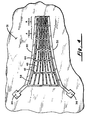
- Fig 4 shows a further improvement to the transducers with hyperbolic shaped electrode fingers of Fig. 3 which may be utilized when it is necessary to further reduce the insertion loss for such transducers.
- This modification involves the segmenting of the fingers of the transducer so that only the two outer, widened electrode fingers 30 and 32, (on a suitable substrate 31, such as a piezoelectric acoustic-wave-propagating medium, or other substrate known to be suitable for the purpose) connect to the opposite electrode pads 34 and 36 respectively, and extend along the entire length of the transducer.
- the remaining inner electrodes extend along only a portion of the outer fingers 30 and 32, and are connected to their respective outer fingers through crossbeams, such as the crossbeams 42, 44.
- a decrease in electrode resistance is obtained which allows the width of the inner electrodes to be sufficiently narrow to produce a transducer which does not have substantially different acoustic impedance than the transducer of Fig. 3.
- the electrical parasitic resistance is approximately decreased by N2 over this transducer, where N is the number of segments, such as the electrode 38 into which each finger electrode is divided. For example, in the embodiment shown in Fig. 4 where there are six segments, the electrode resistance will be approximately 1/36 of the resistance of the transducer shown in Fig. 3.
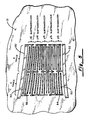
- Fig. 5 shows another modification in which each segment of the transducer may be subdivided to provide a number of subtransducers across the outer electrodes.
- the showing of Fig. 5, for simplification, illustrates only two tracks of the transducer, which correspond to the tracks between the lines A and B of Fig. 4. Interconnections in these tracks provides a number of capacitively coupled, floating electrode subtransducers.
- Fig. 5 there are five subtransducers in each track which are connected in series to provide a voltage dividing path between the electrodes 30, 32.
- capacitive coupling occurs between sections 30 and 50, 32 and 52, 52 and 54, 50 and 56, etc., of Fig. 5.
- acoustic impedance is thus increased by factor N2, where N is the number of subtransducers of each track, over the acoustic impedance of the transducer of Fig. 4.
- N is the number of subtransducers of each track
- the acoustic impedance in increased by a factor of 25, as compared to a transducer with the same number of electrodes but with only one subtransducer per segment as in Fig. 4.
Landscapes
- Physics & Mathematics (AREA)
- Acoustics & Sound (AREA)
- Surface Acoustic Wave Elements And Circuit Networks Thereof (AREA)
Applications Claiming Priority (2)
| Application Number | Priority Date | Filing Date | Title |
|---|---|---|---|
| US06/799,719 US4635008A (en) | 1985-11-19 | 1985-11-19 | Dispersive SAW filter with tapered transducers |
| US799719 | 1985-11-19 |
Publications (2)
| Publication Number | Publication Date |
|---|---|
| EP0223554A2 true EP0223554A2 (de) | 1987-05-27 |
| EP0223554A3 EP0223554A3 (de) | 1989-03-08 |
Family
ID=25176594
Family Applications (1)
| Application Number | Title | Priority Date | Filing Date |
|---|---|---|---|
| EP86308817A Withdrawn EP0223554A3 (de) | 1985-11-19 | 1986-11-12 | Mit akustischen Oberflächenwellen arbeitendes Dispersionsfilter mit keilförmigem Wandler |
Country Status (3)
| Country | Link |
|---|---|
| US (1) | US4635008A (de) |
| EP (1) | EP0223554A3 (de) |
| JP (1) | JPS62120115A (de) |
Cited By (4)
| Publication number | Priority date | Publication date | Assignee | Title |
|---|---|---|---|---|
| DE19646748A1 (de) * | 1996-11-01 | 1998-05-20 | Nanotron Ges Fuer Mikrotechnik | Sicherungssystem |
| DE19646746A1 (de) * | 1996-11-01 | 1998-05-20 | Nanotron Ges Fuer Mikrotechnik | Übertragungsverfahren zur drahtlosen Kommunikation mit einem implantierten medizinischen Gerät |
| US6466609B2 (en) | 1996-11-01 | 2002-10-15 | Nanotron Gesellschaft Fur Mikrotechnik Mbh | Method for wireless information transfer |
| US6614853B1 (en) | 1996-11-01 | 2003-09-02 | Nanotron Gesellschaft Fur Mikrotechnik Mbh | Method of transmission and device to carry out said method |
Families Citing this family (26)
| Publication number | Priority date | Publication date | Assignee | Title |
|---|---|---|---|---|
| JP2561454B2 (ja) | 1985-01-30 | 1996-12-11 | 日本無線株式会社 | 弾性表面波フィルタ |
| GB2193060B (en) * | 1986-07-16 | 1991-04-03 | Japan Radio Co Ltd | Surface elastic wave filter |
| US4737743A (en) * | 1987-06-24 | 1988-04-12 | Unisys Corporation | Single mode waveguide saw dispersive filter |
| US4749971A (en) * | 1987-06-24 | 1988-06-07 | Unisys Corporation | Saw delay line with multiple reflective taps |
| US4767198A (en) * | 1987-06-24 | 1988-08-30 | Unisys Corporation | SAW/BAW Bragg cell |
| US4746882A (en) * | 1987-06-24 | 1988-05-24 | Unisys Corporation | Saw multiplexer using tapered transducers |
| US4908542A (en) * | 1987-06-24 | 1990-03-13 | Unisys | Saw tapered transducers |
| US4849760A (en) * | 1987-11-20 | 1989-07-18 | Unisys Corporation | Surface acoustic wave doppler detector |
| US5179309A (en) * | 1988-02-04 | 1993-01-12 | Trw Inc. | Surface acoustic wave chirp filter |
| JPH0374921A (ja) * | 1989-08-16 | 1991-03-29 | Clarion Co Ltd | 弾性表面波装置 |
| US5113115A (en) * | 1991-06-19 | 1992-05-12 | The United States Of America As Represented By The Secretary Of The Army | Saw slanted array correlator with amplitude error compensating polymer reflective array grating |
| US5363074A (en) * | 1992-10-19 | 1994-11-08 | Motorola, Inc. | Saw structure having serially coupled transducers with overlapping fingers |
| US5289073A (en) * | 1992-11-09 | 1994-02-22 | The United States Of America As Represented By The Secretary Of The Army | Unidirectional surface acoustic wave transducer |
| US5831492A (en) * | 1995-09-15 | 1998-11-03 | Sawtek Inc. | Weighted tapered spudt saw device |
| US5818310A (en) * | 1996-08-27 | 1998-10-06 | Sawtek Inc. | Series-block and line-width weighted saw filter device |
| US5831494A (en) * | 1996-12-12 | 1998-11-03 | Sawtek Inc. | Dual track low-loss reflective saw filter |
| JP3154402B2 (ja) * | 1997-11-12 | 2001-04-09 | 日本電気株式会社 | Sawフィルタ |
| US6239422B1 (en) * | 1999-03-10 | 2001-05-29 | Trw Inc. | Variable electrode traveling wave metal-semiconductor-metal waveguide photodetector |
| DE19925800C1 (de) * | 1999-06-03 | 2000-12-21 | Dresden Ev Inst Festkoerper | Wandler für akustische Oberflächenwellen |
| DE19944452B4 (de) * | 1999-09-16 | 2004-05-06 | Advalytix Ag | Vorrichtung und Verfahren zum Ermitteln des Ortes der Wechselwirkung einer akustischen Oberflächenwelle |
| US6380828B1 (en) | 2000-07-24 | 2002-04-30 | Nortel Networks Limited | Surface wave devices with static electric field |
| US6791236B1 (en) * | 2000-10-11 | 2004-09-14 | Yuri Abramov | Method utilizing the saw velocity dispersion effect for weighting by shaping the electrode fingers of a saw interdigital transducer and apparatus produced thereby |
| DE10113788A1 (de) * | 2001-03-21 | 2002-09-26 | Zeiss Carl | Beugungsoptische Komponente, Beleuchtungssystem und Belichtungssystem mit einer solchen beugungsoptischen Komponente und Belichtungsverfahren unter Verwendung eines solchen Belichtungssystems |
| DE10314153A1 (de) * | 2003-03-28 | 2004-10-07 | Epcos Ag | Oberflächenwellen-Anordnung zur breitbandigen Signalübertragung |
| TW200626893A (en) * | 2005-01-28 | 2006-08-01 | yong-yu Chen | Surface acoustic wave thin-film measuring device and measuring method thereof |
| EP4697345A1 (de) | 2024-08-17 | 2026-02-18 | Maciej Bajer | System zur dynamischen bestimmung der lebensmittelbewertung unter verwendung benutzerprogrammierter funktionen |
Family Cites Families (9)
| Publication number | Priority date | Publication date | Assignee | Title |
|---|---|---|---|---|
| US3568102A (en) * | 1967-07-06 | 1971-03-02 | Litton Precision Prod Inc | Split surface wave acoustic delay line |
| DE2115412A1 (de) * | 1971-03-30 | 1972-10-12 | Siemens Ag | Piezoelektrisches Filter nach dem Oberfl ächenwellenprinzip |
| US3727718A (en) * | 1971-11-24 | 1973-04-17 | Us Navy | Surface wave ambiguity analyzer |
| GB1495147A (en) * | 1974-08-16 | 1977-12-14 | Secr Defence | Surface acoustic wave devices |
| US4166228A (en) * | 1978-03-17 | 1979-08-28 | Sperry Rand Corporation | Temperature compensated reflective array for surface acoustic wave processing |
| US4250474A (en) * | 1979-09-26 | 1981-02-10 | Hughes Aircraft Company | Continuous beam steering acoustic wave transducer |
| FR2520171A1 (fr) * | 1982-01-15 | 1983-07-22 | Thomson Csf | Ligne a retard acoustique dispersive a ondes de surface |
| DE3230566C2 (de) * | 1982-08-17 | 1987-02-05 | Siemens AG, 1000 Berlin und 8000 München | Mit reflektierten akustischen Wellen arbeitendes elektronisches Bauelement |
| US4499393A (en) * | 1984-02-15 | 1985-02-12 | Trw Inc. | Surface acoustic wave spectrum analyzer |
-
1985
- 1985-11-19 US US06/799,719 patent/US4635008A/en not_active Expired - Fee Related
-
1986
- 1986-10-15 JP JP61243333A patent/JPS62120115A/ja active Pending
- 1986-11-12 EP EP86308817A patent/EP0223554A3/de not_active Withdrawn
Cited By (8)
| Publication number | Priority date | Publication date | Assignee | Title |
|---|---|---|---|---|
| DE19646748A1 (de) * | 1996-11-01 | 1998-05-20 | Nanotron Ges Fuer Mikrotechnik | Sicherungssystem |
| DE19646746A1 (de) * | 1996-11-01 | 1998-05-20 | Nanotron Ges Fuer Mikrotechnik | Übertragungsverfahren zur drahtlosen Kommunikation mit einem implantierten medizinischen Gerät |
| US6404338B1 (en) | 1996-11-01 | 2002-06-11 | Nanotron Gesellschaft Fur Mikrootechnik Mbh | Measuring and/or security system |
| US6453200B1 (en) | 1996-11-01 | 2002-09-17 | Nanotron Gesellschaft Fur Mikrotechnik Mbh | Method for wireless communication transfer with an implanted medical device |
| US6466609B2 (en) | 1996-11-01 | 2002-10-15 | Nanotron Gesellschaft Fur Mikrotechnik Mbh | Method for wireless information transfer |
| DE19646748C2 (de) * | 1996-11-01 | 2003-03-20 | Nanotron Ges Fuer Mikrotechnik | Sicherungssystem |
| US6614853B1 (en) | 1996-11-01 | 2003-09-02 | Nanotron Gesellschaft Fur Mikrotechnik Mbh | Method of transmission and device to carry out said method |
| DE19646746C2 (de) * | 1996-11-01 | 2003-09-18 | Nanotron Technologies Gmbh | Übertragungsverfahren zur drahtlosen Kommunikation mit einem implantierten medizinischen Gerät |
Also Published As
| Publication number | Publication date |
|---|---|
| US4635008A (en) | 1987-01-06 |
| JPS62120115A (ja) | 1987-06-01 |
| EP0223554A3 (de) | 1989-03-08 |
Similar Documents
| Publication | Publication Date | Title |
|---|---|---|
| US4635008A (en) | Dispersive SAW filter with tapered transducers | |
| US4908542A (en) | Saw tapered transducers | |
| US4353046A (en) | Surface acoustic wave device with reflectors | |
| EP0850510B1 (de) | Gewichtete keilförmige spudt-saw-vorrichtung | |
| US6791236B1 (en) | Method utilizing the saw velocity dispersion effect for weighting by shaping the electrode fingers of a saw interdigital transducer and apparatus produced thereby | |
| US3975697A (en) | Surface acoustic wave devices | |
| US5289073A (en) | Unidirectional surface acoustic wave transducer | |
| US3882430A (en) | Surface acoustic wave devices | |
| EP0161040A1 (de) | Spektralanalysator mit akustischen Oberflächenwellen | |
| JPS58190117A (ja) | 音響表面波装置 | |
| US5977846A (en) | Unidirectional surface acoustic wave filter | |
| Solie | Tapered transducers-design and applications | |
| US6426584B2 (en) | Elastic wave device | |
| US5336957A (en) | Surface acoustic wave convolver | |
| GB2114393A (en) | Surface wave dispersive acoustic delay line | |
| US5306978A (en) | Surface acoustic wave unidirectional transducer having floating electrodes | |
| CN1864327B (zh) | 声表面波器件 | |
| US6504453B2 (en) | Transversal surface acoustic wave filter | |
| US4520330A (en) | Electronic component functioning with reflected acoustic waves | |
| US5818310A (en) | Series-block and line-width weighted saw filter device | |
| US4114119A (en) | Wide band low loss acoustic wave device | |
| US4749971A (en) | Saw delay line with multiple reflective taps | |
| EP0057332B1 (de) | Symmetrischer Bündelbreitenkompressor mit Mehrfachstreifenkoppler | |
| CN1282145A (zh) | 声表面波装置和通信设备 | |
| US4767198A (en) | SAW/BAW Bragg cell |
Legal Events
| Date | Code | Title | Description |
|---|---|---|---|
| PUAI | Public reference made under article 153(3) epc to a published international application that has entered the european phase |
Free format text: ORIGINAL CODE: 0009012 |
|
| AK | Designated contracting states |
Kind code of ref document: A2 Designated state(s): DE FR GB IT NL |
|
| PUAL | Search report despatched |
Free format text: ORIGINAL CODE: 0009013 |
|
| AK | Designated contracting states |
Kind code of ref document: A3 Designated state(s): DE FR GB IT NL |
|
| 17P | Request for examination filed |
Effective date: 19890427 |
|
| RAP1 | Party data changed (applicant data changed or rights of an application transferred) |
Owner name: UNISYS CORPORATION |
|
| 17Q | First examination report despatched |
Effective date: 19910131 |
|
| STAA | Information on the status of an ep patent application or granted ep patent |
Free format text: STATUS: THE APPLICATION IS DEEMED TO BE WITHDRAWN |
|
| 18D | Application deemed to be withdrawn |
Effective date: 19910611 |
|
| RIN1 | Information on inventor provided before grant (corrected) |
Inventor name: SOLIE, LELAND P. |