EP0223595A2 - Messerbefestigung für Rotorkrümler - Google Patents
Messerbefestigung für Rotorkrümler Download PDFInfo
- Publication number
- EP0223595A2 EP0223595A2 EP86308997A EP86308997A EP0223595A2 EP 0223595 A2 EP0223595 A2 EP 0223595A2 EP 86308997 A EP86308997 A EP 86308997A EP 86308997 A EP86308997 A EP 86308997A EP 0223595 A2 EP0223595 A2 EP 0223595A2
- Authority
- EP
- European Patent Office
- Prior art keywords
- cutter
- rotary
- tilling
- tilling device
- supporting member
- Prior art date
- Legal status (The legal status is an assumption and is not a legal conclusion. Google has not performed a legal analysis and makes no representation as to the accuracy of the status listed.)
- Withdrawn
Links
- 238000005452 bending Methods 0.000 claims description 3
- 230000001419 dependent effect Effects 0.000 claims 1
- 238000005520 cutting process Methods 0.000 abstract description 16
- 239000002689 soil Substances 0.000 description 12
- 244000025254 Cannabis sativa Species 0.000 description 7
- 230000005540 biological transmission Effects 0.000 description 2
- 238000010276 construction Methods 0.000 description 1
- 230000007423 decrease Effects 0.000 description 1
- 238000010586 diagram Methods 0.000 description 1
- 230000005484 gravity Effects 0.000 description 1
- 239000002184 metal Substances 0.000 description 1
- 230000004048 modification Effects 0.000 description 1
- 238000012986 modification Methods 0.000 description 1
- 238000003466 welding Methods 0.000 description 1
Images


Classifications
-
- A—HUMAN NECESSITIES
- A01—AGRICULTURE; FORESTRY; ANIMAL HUSBANDRY; HUNTING; TRAPPING; FISHING
- A01D—HARVESTING; MOWING
- A01D34/00—Mowers; Mowing apparatus of harvesters
- A01D34/01—Mowers; Mowing apparatus of harvesters characterised by features relating to the type of cutting apparatus
- A01D34/412—Mowers; Mowing apparatus of harvesters characterised by features relating to the type of cutting apparatus having rotating cutters
- A01D34/42—Mowers; Mowing apparatus of harvesters characterised by features relating to the type of cutting apparatus having rotating cutters having cutters rotating about a horizontal axis, e.g. cutting-cylinders
- A01D34/52—Cutting apparatus
- A01D34/535—Cutting apparatus with cutting members pivotally attached to the rotating axle, e.g. flails
-
- A—HUMAN NECESSITIES
- A01—AGRICULTURE; FORESTRY; ANIMAL HUSBANDRY; HUNTING; TRAPPING; FISHING
- A01B—SOIL WORKING IN AGRICULTURE OR FORESTRY; PARTS, DETAILS, OR ACCESSORIES OF AGRICULTURAL MACHINES OR IMPLEMENTS, IN GENERAL
- A01B33/00—Tilling implements with rotary driven tools, e.g. in combination with fertiliser distributors or seeders, with grubbing chains, with sloping axles, with driven discs
- A01B33/08—Tools; Details, e.g. adaptations of transmissions or gearings
- A01B33/14—Attaching the tools to the rotating shaft, e.g. resiliently or flexibly-attached tools
- A01B33/142—Attaching the tools to the rotating shaft, e.g. resiliently or flexibly-attached tools the rotating shaft being oriented horizontally
- A01B33/144—Attaching the tools to the rotating shaft, e.g. resiliently or flexibly-attached tools the rotating shaft being oriented horizontally with spring tools or resiliently-attached rigid tools
Definitions
- the present invention relates to a mounting structure for cutters for a rotary tilling device having a rotary cutting device.
- the rotary cutters in such a rotary cutting device rotate downwardly or upwardly in the soil to break up the surface soil.
- the conventional rotary tilling device is used only for cultivating the soil and is not constructed to perform other work such as mowing, for example of grass.
- each cutter is rotatably mounted on a pivotal member, such as a bolt secured to supporting member, and held at an angular position by a stopper when tilling.
- a lateral gap is provided between the cutter and fastening means in order to allow it to rotate about the bolt. Accordingly, load exerted on the cutter during the tilling operation causes shifting thereof in the lateral direction of the tilling device ( in the axial direction of the bolt). The continuous lateral shifting or reciprocating of the cutter decreases the workability of the device. Further, since the cutter is rotatable about the bolt in the opposite direction when tilling, the cutter may swing during operation, which causes an unstable tilling operation.
- the present invention seeks to provide a mounting structure which may secure each cutter in the tilling position when tilling and may release the cutter when mowing.
- a rotary tilling device comprising a rotary shaft rotatably supported on frame means, a plurality of supporting members secured to the rotary shaft, at least two cutters rotatably mounted by a bolt on each of the supporting members at opposite positions thereof, each of the cutters having a vertical portion, a base end portion at which the cutter is rotatable about the bolt, and a lateral portion bending at another end of the vertical portion in the axial direction of the rotary shaft, and having a tilling (soil cutting) edge and a mowing (grass cutting) edge on sides of both the vertical and lateral portions, holding means provided on the supporting member for holding the cutter in the tilling position and for releasing the cutter in the mowing position, and transmitting means for transmitting power of a tractor to the rotary shaft to rotate it.
- the holding means comprises a stopper provided on the supporting member and a holding member having a resilient portion for urging the cutter to the supporting member.
- a rotary tilling device 1 is adapted to be drawn by a tractor T and attached thereto by a three-point linkage (not shown) so as to be lowered and raised.
- the rotary tilling device 1 has a gearbox 2 provided at a middle portion relative to the lateral direction thereof, an output shaft 12 projecting from the gearbox 2, a downwardly extending chain case 15 from the end of the output shaft 12 and supporting frame 17 provided at the other side of the machine.
- the gearbox 2 has an input shaft 3, one end of which is connected to the tractor T by way of a universal joint, transmission shaft and power take-off shaft.
- a bevel gear 4 fixedly mounted on the other end of the input shaft 3, engages with a bevel gear 6 mounted on an intermediate shaft 5.
- a gear 7 secured to the intermediate shaft 5 is engaged with a gear 9 rotatably mounted on the output shaft 12, providing a large reduction ratio.
- a gear 8 also securely mounted on the intermediate shaft 5 engages an idler gear 10, which in turn engages a counter gear 11 rotatably mounted on the output shaft 12.
- a shift gear 13 is slidably secured by a spline engagement to the output shaft 12.
- the gear 13 is selectively engaged with gears 9 and 11, in order to operatively connect the gear 9 or 11 with the output shaft 12.
- a shift lever 14 projecting from the gear box 2 is connected with the slidable gear 13 for the selecting operation.
- the output shaft 12 has a sprocket wheel 16 at an end portion.
- the sprocket wheel 16 is connected to a sprocket wheel 19 fixedly mounted on a rotary shaft 18 through a chain 20.
- the rotary shaft 18 is rotatably supported on lower portions of the chain case 15 and the supporting frame 17.
- a rotary cutting device R has a plurality of supporting members 21 (Figure 2a) radially and securely mounted on the rotary shaft 18. On opposite end portions of the supporting members 21, cutters 23 are pivotally . supported by pivot bolts 22, respectively. As shown in Figures 5a to 5c, each cutter 23 is made by bending a rectangular metal plate to form a vertical portion 23a and a lateral portion 23b thereby forming a substantially L shape section. A soil cutting edge 23c and a grass cutting edge 23d are formed on opposite sides of a lower portion of the vertical portion 23a and on opposite sides of the lateral portion 23b, edge 23c being for tilling and 23d for mowing.
- a holding plate 26 is secured to shaft 18 by welding and the cutter 23 is disposed between the supporting member 21 and holding plate 26.
- a stopper 24 is provided on the supporting member 21 to receive the load exerted on the cutter 23.
- the stopper 24 has an abutment side 24a against which one side of the cutter 23 abuts.
- the cutter In a tilling position shown by a solid line in Figure 2a, the cutter has an angular disposition for tilling.
- the stopper 24 is so positioned to ensure that the cutter 23 is inserted into the soil at a certain entering angle 8 ( Figure 2a) for efficient inverting and turning of soil.
- a spring plate 25 is attached on the bolt 22.
- the spring plate 25 has bent portion 25b engaging with the cutter 23 to urge it towards the supporting member 21.
- the spring plate 25 has protruding portion 25a which engages with a notch 24b of the stopper 24 as shown in Figure 2b, so that the spring plate is prevented from rotating about the bolt 22.
- covers 26 and 27 are provided above the front and rear portions of the rotary tilling device 1.
- the cutter 23 For effective grass cutting, it is preferable to mount the cutter 23 on the supporting member 21 so as to form a certain angle between the surface of the ground and the bottom of the cutter 23.
- the center 0 of a hole 23e for securing the cutter by bolt 22 is deflected by a mm from a center line L,of the cutter 23 towards the soil cutting edge 23c.
- the shift lever 14 is shifted so that the shift gear 13 is in engagement with the gear 9. Accordingly, the power of the engine supplied to the input shaft 3 is transmitted to the output shaft 12 through bevel gears 4 and 6, and gears 7 and 9. The power is further transmitted to the rotary shaft 18 through the sprocket wheels 16, 19 and the chain 20. Accordingly, the rotary shaft 18 is rotated at a low speed in the tilling direction. As shown in Figure 3, as the tractor draws the rotary tilling device 1, the edge 23c of each cutter 23 cuts through the soil to cultivate the surface of the soil.
- the abutment side 24a of the stopper 24 holds the cutter 23 at one side thereof preventing the cutter 23 from further rotating in the counter-tilling direction due to the load exerted on the cutter 23.
- the soil is cultivated by the tilling device. Since the cutter 23 is urged to the supporting member 21 by bent portion 25b of the spring plate 25, it is restrained from deflecting in the axial direction of the bolt 22.
- the device When the shift lever 14 is shifted to engage the shift gear 13 with the reverse gear 11, the device is in the state for the grass cutting operation.
- the direction of the rotation of the rotary shaft 18 is in reverse to that of the tilling direction. Since reverse gear 11 is smaller than gear 9, the speed of the rotation of the rotary shaft 18 is faster than the tilling operation thereby generating a large centrifugal force. Accordingly, the cutter 23 is disengaged from the stopper 24 and rotates about the bolt 22 and is held at a radial position shown by a chain line of Figure 2b. As a result, grass growing on unplowed land is cut in the same manner as with a conventional rotary flail-type cutter.
- FIGS 6 to 10 show other embodiments of the present invention.
- the same numerals as those used in the description of the first embodiment designate the same parts.
- the second embodiment has the same construction as the first embodiment except that a collar 29 having a thickness slightly larger than the cutter 23 is embedded in the hole 23e. Therefore, the holding plate 26 is firmly pressed against the supporting member 21 through the collar 29, keeping a lateral gap between the cutter 23 and the holding plate 26 to allow the cutter to rotate freely for the mowing operation.
- the spring plate 25 in previous embodiments is omitted.
- the holding plate 26 of this embodiment has an extension having an elasticity in the lateral direction of the supporting member 21. Namely, the holding plate 26 is bent toward the supporting member 21 at a portion adjacent the stopper 24, thereby forming a bent portion 26a.
- the cutter 23 is inserted between the supporting member 21 and the bent portion 26a so as to be securely held without deflecting in the axial deflection of the bolt 22.
- a disk spring 30 is provided instead of spring plate 25.
- the cutter 23 has a projection 23f which engages with a hole 21a formed in the supporting member 21 when the . cutter 23 is at a tilling position. Accordingly, the cutter 23 is rigidly mounted on the supporting member 21 and locked in the tilling position shown by a chain line in Figure 8a by the engagement of the projection 23f and the hole 21a.
- the cutter 23 in the fifth embodiment is provided with an elongated projection 23g.
- the holding plate 26 has a projection 26a.
- the projections 23g and 26a are adapted to engage with each other with a high friction while cutter 23 is held at the tilling position shown by a chain line in Figure 9a. Accordingly, the movement of the cutter 23 is restricted by the projection 26a, thereby preventing the reciprocating movement thereof between the mowing position shown by a solid line and the tilling position.
- a bracket 32 to which one end of a leaf spring 31 is secured is attached to the supporting member 21 below the stopper 24.
- the other end portion of the leaf spring 31 abuts against the base portion formed in a semi-circle having a radius r about a center P.
- the leaf spring 31 is biased to abut against one of sides of the vertical portion 23a of the cutter 23 opposite the soil cutting edge 23c, so that the force of the leaf spring 31 is exerted thereto above the center 0. Accordingly, the cutter 23 is resiliently held in the tilling position.
- the stopper 24 is secured to the supporting member 21 by a shear bolt 33 together with a spring plate 34.
- the spring plate 34 prevents the cutter 23 from deflecting in the axial direction of the bolt. If excessive load is exerted on the cutter 23 during tilling operation, the shear bolt 33 is sheared to that the stopper 24 no longer holds the cutter 23. Accordingly, the cutter 23 is rotated in the counter-tilling directiom without any damage. After the shear bolt 33 has been replaced by a new one, the rotary cutting device is ready for'operation.
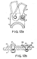
- Figures 12a and 12b show another embodiment employing such a shear bolt 33.
- a disk spring 35 serves both as a stopper 24 and spring plate 34 of the embodiment described in Figure 11.
- the disk spring 35 employed in this embodiment consists of a central portion 35a and a flange 35b. The central portion serves to stop the further rotation of the cutter 23 in the counter-tilling direction during the tilling operation.
- the cutter 23 is interposed between the flange 35b and the supporting member 21. Since the disk spring need not be orientated in any particular direction, it is not required to secure the disk spring 35 to other parts of the device such as rotary shaft 18.
- the shear bolt 33 works in the same way as in the afore-described embodiment so that the disk spring 35 falls off, allowing the cutter 23 to rotate freely.
Landscapes
- Life Sciences & Earth Sciences (AREA)
- Environmental Sciences (AREA)
- Engineering & Computer Science (AREA)
- Mechanical Engineering (AREA)
- Soil Sciences (AREA)
- Soil Working Implements (AREA)
Applications Claiming Priority (4)
| Application Number | Priority Date | Filing Date | Title |
|---|---|---|---|
| JP26195985A JPS62122504A (ja) | 1985-11-20 | 1985-11-20 | 耕うん草刈り装置における爪の装着方法 |
| JP261959/85 | 1985-11-20 | ||
| JP26295785A JPS62122503A (ja) | 1985-11-22 | 1985-11-22 | 耕うん草刈り装置における爪の装着方法 |
| JP262957/85 | 1985-11-22 |
Publications (2)
| Publication Number | Publication Date |
|---|---|
| EP0223595A2 true EP0223595A2 (de) | 1987-05-27 |
| EP0223595A3 EP0223595A3 (de) | 1988-07-20 |
Family
ID=26545317
Family Applications (1)
| Application Number | Title | Priority Date | Filing Date |
|---|---|---|---|
| EP86308997A Withdrawn EP0223595A3 (de) | 1985-11-20 | 1986-11-18 | Messerbefestigung für Rotorkrümler |
Country Status (3)
| Country | Link |
|---|---|
| US (1) | US4804047A (de) |
| EP (1) | EP0223595A3 (de) |
| AU (1) | AU569669B2 (de) |
Cited By (2)
| Publication number | Priority date | Publication date | Assignee | Title |
|---|---|---|---|---|
| EP0393337A3 (de) * | 1989-04-21 | 1991-06-05 | H. Niemeyer Söhne GmbH & Co. KG | Bodenbearbeitungswerkzeug |
| CN108925221A (zh) * | 2018-07-05 | 2018-12-04 | 中南林业科技大学 | 一种双轴双速式除草机及除草方法 |
Families Citing this family (8)
| Publication number | Priority date | Publication date | Assignee | Title |
|---|---|---|---|---|
| AU6426090A (en) * | 1989-09-18 | 1991-04-18 | Kverneland Underhaug As | Rotary agricultural tool |
| WO1992016097A1 (en) * | 1991-03-22 | 1992-10-01 | Walter Oechsle | Reels for combing, raking, or vertical cutting of grassed or other ground |
| NL1018565C2 (nl) * | 2001-07-17 | 2003-01-20 | Jacob Jacobus Rodenburg | Werkwijze en inrichting voor het bewerken van een grasmat, zoals voor het verwijderen van gras, van de grasmat op zich dan wel van een dergelijk materiaal. |
| NL1035035C2 (nl) * | 2008-02-18 | 2009-08-19 | Lely Patent Nv | Maai-inrichting. |
| US8221203B1 (en) | 2011-02-04 | 2012-07-17 | Cnh America Llc | Knives for rotary chopper assembly of a combine harvester |
| WO2014160474A1 (en) * | 2013-03-13 | 2014-10-02 | Andros Engineering Corporation | Device and method for separating plant material from a bed of plants |
| US10206330B1 (en) * | 2017-05-17 | 2019-02-19 | Loren A. Lund | Sapling reducing apparatus |
| US10575471B2 (en) * | 2017-05-30 | 2020-03-03 | Deere & Company | Agricultural combine with reversing chopper rotor |
Family Cites Families (17)
| Publication number | Priority date | Publication date | Assignee | Title |
|---|---|---|---|---|
| FR459039A (fr) * | 1912-06-22 | 1913-10-24 | Josef Tanczer | Machine à travailler le sol |
| US2990667A (en) * | 1959-08-11 | 1961-07-04 | Sperry Rand Corp | Forage harvester |
| US3093951A (en) * | 1959-12-07 | 1963-06-18 | Int Harvester Co | Multiple knife assembly for forage choppers |
| US3128729A (en) * | 1960-05-24 | 1964-04-14 | James A Henson | All-purpose farm machine |
| DE1137887B (de) * | 1960-05-27 | 1962-10-11 | Yuba Cons Ind Inc | Anordnung von Zinken zur Bodenbearbeitung |
| US3028919A (en) * | 1960-11-04 | 1962-04-10 | Smith Alexander | Mower and hoe |
| US3460629A (en) * | 1965-03-29 | 1969-08-12 | Scott & Sons Co O M | Lawn care apparatus |
| AU4781464A (en) * | 1965-08-05 | 1967-02-09 | Rover Mowers Pty. Ltd | Improvements in and relating to rotary mowers tillers and similar machines |
| NL6614376A (de) * | 1966-10-13 | 1968-04-16 | ||
| DE2551857C3 (de) * | 1974-04-18 | 1980-11-13 | Josef Willibald, Maschinenfabrik, 7771 Frickingen | Landwirtschaftliches Bodenbearbeitungsgerät |
| DD146884A1 (de) * | 1979-12-20 | 1981-03-11 | Wolfgang Hummel | Spannsystem fuer messer mit winkelfoermigem querschnitt |
| US4492271A (en) * | 1982-07-12 | 1985-01-08 | Brinly-Hardy Co., Inc. | Tine tiller with tines and wheels each rotatable in either direction |
| AU1779283A (en) * | 1982-07-28 | 1984-02-23 | Byrd George Malcolm | Improvements relating to rotary agitators |
| JPS5985203A (ja) * | 1982-11-06 | 1984-05-17 | 株式会社クボタ | 正逆転両用形耕耘爪の取付け構造 |
| US4519459A (en) * | 1983-03-31 | 1985-05-28 | Magna American Corporation | Power drive rear tine tiller with reversing gear transmission for the tines |
| US4611669A (en) * | 1984-03-29 | 1986-09-16 | Mtd Products Inc. | Tine assembly |
| US4805704A (en) * | 1985-10-12 | 1989-02-21 | Kobashi Kogyo Co., Ltd. | Rotary tilling device |
-
1986
- 1986-11-17 US US06/931,743 patent/US4804047A/en not_active Expired - Fee Related
- 1986-11-18 EP EP86308997A patent/EP0223595A3/de not_active Withdrawn
- 1986-11-18 AU AU65399/86A patent/AU569669B2/en not_active Ceased
Cited By (2)
| Publication number | Priority date | Publication date | Assignee | Title |
|---|---|---|---|---|
| EP0393337A3 (de) * | 1989-04-21 | 1991-06-05 | H. Niemeyer Söhne GmbH & Co. KG | Bodenbearbeitungswerkzeug |
| CN108925221A (zh) * | 2018-07-05 | 2018-12-04 | 中南林业科技大学 | 一种双轴双速式除草机及除草方法 |
Also Published As
| Publication number | Publication date |
|---|---|
| EP0223595A3 (de) | 1988-07-20 |
| AU6539986A (en) | 1987-05-28 |
| US4804047A (en) | 1989-02-14 |
| AU569669B2 (en) | 1988-02-11 |
Similar Documents
| Publication | Publication Date | Title |
|---|---|---|
| US4805704A (en) | Rotary tilling device | |
| US4778012A (en) | Rotary tilling and grass cutting device | |
| US8510959B2 (en) | Quick-change disc mower knives | |
| EP0223595A2 (de) | Messerbefestigung für Rotorkrümler | |
| US4492271A (en) | Tine tiller with tines and wheels each rotatable in either direction | |
| US4567949A (en) | Soil tilling machine with transmission having three drive trains | |
| US4615395A (en) | Reversible rotary cultivating apparatus | |
| US20040149466A1 (en) | Gear mechanism having protection against wrapping | |
| US6502377B2 (en) | Brake for a disc cutterbar | |
| JPH0458285B2 (de) | ||
| JPS6325923Y2 (de) | ||
| JPH0458286B2 (de) | ||
| JP3062795B2 (ja) | 同軸正逆転作業機 | |
| JPS6239607Y2 (de) | ||
| JPH0646882B2 (ja) | 耕うん草刈り装置 | |
| JPS6239606Y2 (de) | ||
| JP2532784Y2 (ja) | 牽引型対地作業機の駆動装置 | |
| JPS62151101A (ja) | ロ−タリ農作業機 | |
| JPS6251764B2 (de) | ||
| JPH0119601Y2 (de) | ||
| JPS6287006A (ja) | 正逆回転ロ−タリ装置 | |
| JPH0642405Y2 (ja) | アツプカツト耕法による耕うん爪 | |
| JPS62257304A (ja) | 正逆回転ロ−タリ耕うん爪 | |
| JPS6239608Y2 (de) | ||
| NL8302906A (nl) | Grondbewerkingsmachine. |
Legal Events
| Date | Code | Title | Description |
|---|---|---|---|
| PUAI | Public reference made under article 153(3) epc to a published international application that has entered the european phase |
Free format text: ORIGINAL CODE: 0009012 |
|
| 17P | Request for examination filed |
Effective date: 19861128 |
|
| AK | Designated contracting states |
Kind code of ref document: A2 Designated state(s): AT CH DE ES FR GB IT LI |
|
| PUAL | Search report despatched |
Free format text: ORIGINAL CODE: 0009013 |
|
| AK | Designated contracting states |
Kind code of ref document: A3 Designated state(s): AT CH DE ES FR GB IT LI |
|
| 17Q | First examination report despatched |
Effective date: 19900924 |
|
| STAA | Information on the status of an ep patent application or granted ep patent |
Free format text: STATUS: THE APPLICATION IS DEEMED TO BE WITHDRAWN |
|
| 18D | Application deemed to be withdrawn |
Effective date: 19910205 |
|
| RIN1 | Information on inventor provided before grant (corrected) |
Inventor name: KOBIKI, YASUHIROC/O KOBASHI KOGYO CO., LTD. Inventor name: KOBASHI, TERUHISAC/O KOBASHI KOGYO CO., LTD. Inventor name: KOBASHI, ICHIROC/O KOBASHI KOGYO CO., LTD. Inventor name: TOUKI, YOSHIOC/O KOBASHI KOGYO CO., LTD. |