EP0223611A2 - Méthode pour signaler des secteurs défectueux dans un appareil à disques - Google Patents
Méthode pour signaler des secteurs défectueux dans un appareil à disques Download PDFInfo
- Publication number
- EP0223611A2 EP0223611A2 EP86309065A EP86309065A EP0223611A2 EP 0223611 A2 EP0223611 A2 EP 0223611A2 EP 86309065 A EP86309065 A EP 86309065A EP 86309065 A EP86309065 A EP 86309065A EP 0223611 A2 EP0223611 A2 EP 0223611A2
- Authority
- EP
- European Patent Office
- Prior art keywords
- disc
- defect list
- disc drive
- sector
- drive
- Prior art date
- Legal status (The legal status is an assumption and is not a legal conclusion. Google has not performed a legal analysis and makes no representation as to the accuracy of the status listed.)
- Withdrawn
Links
Images

Classifications
-
- G—PHYSICS
- G06—COMPUTING OR CALCULATING; COUNTING
- G06F—ELECTRIC DIGITAL DATA PROCESSING
- G06F3/00—Input arrangements for transferring data to be processed into a form capable of being handled by the computer; Output arrangements for transferring data from processing unit to output unit, e.g. interface arrangements
- G06F3/06—Digital input from, or digital output to, record carriers, e.g. RAID, emulated record carriers or networked record carriers
- G06F3/0601—Interfaces specially adapted for storage systems
-
- G—PHYSICS
- G11—INFORMATION STORAGE
- G11B—INFORMATION STORAGE BASED ON RELATIVE MOVEMENT BETWEEN RECORD CARRIER AND TRANSDUCER
- G11B20/00—Signal processing not specific to the method of recording or reproducing; Circuits therefor
- G11B20/10—Digital recording or reproducing
- G11B20/18—Error detection or correction; Testing, e.g. of drop-outs
- G11B20/1883—Methods for assignment of alternate areas for defective areas
-
- G—PHYSICS
- G11—INFORMATION STORAGE
- G11B—INFORMATION STORAGE BASED ON RELATIVE MOVEMENT BETWEEN RECORD CARRIER AND TRANSDUCER
- G11B20/00—Signal processing not specific to the method of recording or reproducing; Circuits therefor
- G11B20/10—Digital recording or reproducing
- G11B2020/10916—Seeking data on the record carrier for preparing an access to a specific address
-
- G—PHYSICS
- G11—INFORMATION STORAGE
- G11B—INFORMATION STORAGE BASED ON RELATIVE MOVEMENT BETWEEN RECORD CARRIER AND TRANSDUCER
- G11B2220/00—Record carriers by type
- G11B2220/20—Disc-shaped record carriers
Definitions
- This invention relates generally to magnetic disc memory apparatus and more particularly to means for improving performance of a disc drive by improved defect management.
- Disc drive systems record and reproduce information stored on concentric circular tracks recorded on magnetic discs.
- the tracks are written and read by a magnetic transducer which cooperates with the surface of the disc.
- the transducer is positioned over a selected track or cylinder on the disc by an actuator mechanism.
- a typical linear actuator for positioning the transducers in alignment with a selected cylinder or track on the surface of a disc is found in our U .S. Patent 4,323,939; a rotary actuator incorporating a stepper motor for positioning a transducer is found in our E . P .--A- 0162614A. Both are incorporated herein by reference.
- Disc drives are microprocessor controlled.
- the microprograms typically provided for disc drive controllers are required to meet strict customer and IO interface requirements.
- the interface requirements and the size of the programs require long development and test cycles before the programs can be committed to ROM or EPROM for production. Once the commitment has been made to put a program in ROM, it is difficult to correct any problems.
- products manufactured in high volume, with microprograms stored in ROM memory have high cost per engineering changes which affect the ROMs, i.e., require scrapping the ROMs which have been previously manufactured.
- ROM/EPROM based products are difficult to customize for specific customer requirements, as each modification to the program requires a new ROM or EPROM.
- a further objective of this invention is to improve the system for controlling the data transducer in rotating disc data storage equipment.
- Another objective herein is to improve the performance and reliability of rotating disc data storage devices while reducing its complexity and cost of manufacture.
- a further objective of this invention is to increase the capacity of the rotating disc data storage device without increasing its complexity or cost of manufacture.
- Yet another objective of this invention is to provide a more efficient approach to defect management. More specifically, in typical disc drive systems, any defective block on a track will cause the entire track to be flagged as defective. This results in a considerable loss in capacity.
- Yet another objective of this invention is to provide a rotating disc data storage device with internal means for dynamically storing a defect list at a sector level to enhance maintenance and adjustment of the device.
- Another objective of this invention is to provide a means for storing a data list which may be comprised of both the manufacture generated data defect list and a user supply defect list.
- a data list which may be comprised of both the manufacture generated data defect list and a user supply defect list.
- Such storage of a manufacturer's defect list in dynamic memory will allow it to be generated by special test equipment, saved on disc in a specially protected area, and accessed by the controller to directly bypass defects without unnecessary seeking steps.
- defect management approach also allows for a user supplied defect list which may be added to the manufacturer's defect list, saved on the disc for future format operations and if necessary removed on command.
- a disc drive wherein two outer tracks of the disc in a region beyond the defined track 0 are used to store the drive operating microprogram, and/or manufacturing test program and/or specific mechanical perameters and media defect information. This information can be read from these outer tracks of the disc during initialization of the disc drive, or during seek operations of the drive. It allows the disc drive to react to microprogram problems without changing either a mask ROM or an EPROM. The microprogram is read onto the drive over the IO interface.
- the product yield is also improved by this process as specific mechanical yield on electrical perameters can be adapted to by including these in the dr.ive micrpprogram.
- the defect list is stored as supplied by the manufacturer on the outer track of the drive. It is merged with the user supplied defect during formatting and used during formatting to flag defective sectors. During initialization of the disc drive, the defect list is loaded into a section of dynamic memory so that it is quickly accessible during seeking of a particular address.
- the defect list can be accessed, and the positioning command is modified to avoid accessing of a defective block, instead directly accessing the next fully effective block.
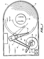
- the typical disc drive as shown in FIG 1 includes a plurality of discs 12 stacked on a spindle 25 for rotation by a spindle motor.
- a transducer 10 is positioned over any of the tracks 0-6 8 5 for reading or writing data on the selected track.
- the positioning occurs under control of a stepper motor 30 in response to commands from a microprocessor 40.
- Rotation of the stepper motor 30 and its spindle 36 causes a band 38 which is connected to the head 19 of arm 32 to wind and unwind on the spindle 36, moving the arm 20 and associated transducer 10 to the selected track.
- the drive has two additional cylinders identified as -1 and -2 cylinders, with four tracks each, formatted 256 bytes per sector, 32 sectors per track and with a 1 to 1 interleave factor.
- the objective of this invention is to minimize the time spent in mechanically seeking for the correct track. Such improper seeking can occur if the original seek is carried out to a block or track which is in fact defective.
- Such disc media defects fall into two categories.
- One category comprises defects identified by the manufacturer during the course of testing, using stress enlarging techniques. These defects are supplied in a list in cylinder, head, and bytes from index formats.
- An example of the numbering scheme appears in FIG 3.
- the cylinder 0 is a reference to the fact that in a disc drive having multiple data storage surfaces on discs, track 0 on each disc is defined as lying on a single cylinder 0.
- a separate head or transducer 10 reads and writes the data on each disc surface. Therefore, a particular location in any disc surface may be particularly identified by defining the cylinder and the head number (these two together combining to identify a particular track on a particular disc surface) followed by identifying a particular sector.
- defects which must be taken into account are those identified by the user over a period of time. These defects are supplied in a list in logical block address format.
- the defect information and operating systems and the like may be stored on a disc drive for ready access in the disc drive on tracts -1 and -2 identified above.
- the manufacturer's defect list is converted into a physical cylinder, head, sector format to make up the known defect list.
- the defective sectors are flagged so that they are functionally bypassed.
- a method is provided for the user to add defects to the known defect list using logical block address format. (It is well known in the disc drive field to convert logical block addresses into cylinder head and sector addresses as most seek commands are initially input as logical block addresses.)
- the added defects are converted to physical cylinder head sector format, taking into account previous defects and the interleave factor in the discs.
- the logical block address is translated into cylinder head and sector addresses and adjusted for defects to avoid performance hits during seek.
- the first step is the conversion of the manufacturer's defect list into a physical cylinder, head, sector format.
- the last number in the known defect list is a relative defect in the list with the first entry being 1, the second entry 2, the third entry 3, and so on. All of this technique is well known in this technology.
- the objective is to provide a list of defects defined in terms of cylinder head and sector on the disc of a particular disc drive.
- the defective sectors are flagged so that they are functionally bypassed.
- the disc is incrementally formatted a track at a time, starting at cylinder 0, track 0, to cylinder 614, track 3.
- the first sector on cylinder 0 track 0 is formatted as logical block 0.
- the logical block address is incremented across the entire disc and not reset to 0 on track or cylinder boundaries.
- a table with an entry for each physical sector on the track is generated. Referencing the known defect list, any defective sectors are marked defective. The remaining sectors are numbered taking into account the interleave factor.
- the defective sector does not get a logical block address and does not cause a logical block address to be skipped. It merely means one less logical block for each defect encountered.
- this step is basically an extension of known formatting and sector addressing techniques, with the only modification being in the numbering scheme to take into account the defects which have been identified so that they are not given addresses and are not addressed during any data access command.
- the user can add defects to the known defect list using logical block address format, simply by using the standard manual format commands which are well known in the disc drive industry.
- the added defects are converted to cylinder head and sector format taking into account previous defects and the interleave factor. Thus, these are simply eliminated as possible addresses for data storage so that they are not reaccessed.
- the added defects are merged with the known defect list into a scratch pad area, in the microprocessor 40, then copied back into the known defect list so that a single merged list is generated.
- a read command which comprises a logical block address as shown in FIG 2 is received, it is converted into a cylinder head and sector address and adjusted for defects to avoid performance hits during seek time.
- the known defect list is loaded into a RAM 41 which is part of MBU 40. (In this way, when new defects are added by a format command by the user, the new known defect list is written back to the -2 cylinder so that the latest updated defect list is always available to upload a power on time during operation is always available in the RAM 41.)
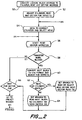
- Read/write and seek commands are presented in logical block format to the microprocessor 40.
- the logical block address is converted to target cylinder head and sector address at step 50. This alone would be enough information to correctly position the actuator head and select the correct head if there were no defects.
- the average seek time for such an operation is 65 milliseconds, with track time being 20 milliseconds.
- the computed cylinder head and sector can be accurately corrected for defects as shown in the following steps in approximately 70 microseconds, thus avoiding a 60 ms to 20 ms seek to wrong track and a subsequent 20 ms to 65 ms reseek to the correct track is a considerable time saver.
- a seek to correct cylinder and head is immediately achieved.
- step 52 a seek to the correct cylinder and head position is immediately done and a read operation conducted at 56. If more blocks are to be transferred as shown at the decision block 58, the next block is converted to cylinder head sector format at step 60; the necessary cylinder or head switch is carried out at step 62; and a branch is carried out to select the correct head. Then the program returns to step 54 to seek to cause the actuator to seek the correct track address. If no cylinder or head switch is required at step 62, the next block is immediately read at step 64 followed by a return to the command to wait for the end of the. sector at 66 and then branching to the finish of the program.
Landscapes
- Engineering & Computer Science (AREA)
- Theoretical Computer Science (AREA)
- Signal Processing (AREA)
- Human Computer Interaction (AREA)
- Physics & Mathematics (AREA)
- General Engineering & Computer Science (AREA)
- General Physics & Mathematics (AREA)
- Signal Processing For Digital Recording And Reproducing (AREA)
- Rotational Drive Of Disk (AREA)
- Control Of Stepping Motors (AREA)
Applications Claiming Priority (2)
| Application Number | Priority Date | Filing Date | Title |
|---|---|---|---|
| US800062 | 1985-11-20 | ||
| US06/800,062 US4746998A (en) | 1985-11-20 | 1985-11-20 | Method for mapping around defective sectors in a disc drive |
Publications (2)
| Publication Number | Publication Date |
|---|---|
| EP0223611A2 true EP0223611A2 (fr) | 1987-05-27 |
| EP0223611A3 EP0223611A3 (fr) | 1988-09-21 |
Family
ID=25177415
Family Applications (1)
| Application Number | Title | Priority Date | Filing Date |
|---|---|---|---|
| EP86309065A Withdrawn EP0223611A3 (fr) | 1985-11-20 | 1986-11-19 | Méthode pour signaler des secteurs défectueux dans un appareil à disques |
Country Status (4)
| Country | Link |
|---|---|
| US (1) | US4746998A (fr) |
| EP (1) | EP0223611A3 (fr) |
| JP (1) | JP2635032B2 (fr) |
| AU (1) | AU591945B2 (fr) |
Cited By (5)
| Publication number | Priority date | Publication date | Assignee | Title |
|---|---|---|---|---|
| EP0328240A3 (en) * | 1988-02-08 | 1990-09-12 | International Business Machines Corporation | Managing data storage space on large capacity record media |
| DE4011052A1 (de) * | 1989-05-19 | 1990-11-22 | Tokico Ltd | Datenspeicherplattengeraet und verfahren zum speichern von daten |
| US5132853A (en) * | 1988-02-08 | 1992-07-21 | International Business Machines Corporation | Allocation procedures for optical disk recorders |
| EP0488700A3 (en) * | 1990-11-30 | 1992-09-09 | Fujitsu Limited | Disk track emulation system and method |
| EP0440413A3 (en) * | 1990-02-02 | 1994-09-14 | Seagate Technology | Disk drive system and method for accessing a physical memory location therein |
Families Citing this family (69)
| Publication number | Priority date | Publication date | Assignee | Title |
|---|---|---|---|---|
| DE3776928D1 (de) * | 1986-03-19 | 1992-04-09 | Fujitsu Ltd | Regelsystem zum spurzugriff fuer ein magnetplattensystem. |
| EP0272029B1 (fr) * | 1986-12-19 | 1993-09-15 | Matsushita Electric Industrial Co., Ltd. | Disque optique effaçable et appareil pour enregistrer et reproduire optiquement des informations comprenant un dispositif pour gérer les secteurs défectueux |
| JP2562823B2 (ja) * | 1987-09-14 | 1996-12-11 | パイオニア株式会社 | 書込み可能型ディスク用オートチェンジャー |
| US5146571A (en) * | 1988-03-28 | 1992-09-08 | Emc Corporation | Remapping defects in a storage system through the use of a tree structure |
| US5268319A (en) | 1988-06-08 | 1993-12-07 | Eliyahou Harari | Highly compact EPROM and flash EEPROM devices |
| US5075804A (en) * | 1989-03-31 | 1991-12-24 | Alps Electric Co., Ltd. | Management of defect areas in recording media |
| US7190617B1 (en) * | 1989-04-13 | 2007-03-13 | Sandisk Corporation | Flash EEprom system |
| US7447069B1 (en) | 1989-04-13 | 2008-11-04 | Sandisk Corporation | Flash EEprom system |
| US5535328A (en) * | 1989-04-13 | 1996-07-09 | Sandisk Corporation | Non-volatile memory system card with flash erasable sectors of EEprom cells including a mechanism for substituting defective cells |
| DE69024086T2 (de) | 1989-04-13 | 1996-06-20 | Sundisk Corp | EEprom-System mit Blocklöschung |
| JP2715154B2 (ja) * | 1989-09-12 | 1998-02-18 | 京セラ株式会社 | 磁気ディスク装置 |
| US5271018A (en) * | 1990-04-27 | 1993-12-14 | Next, Inc. | Method and apparatus for media defect management and media addressing |
| JP2851982B2 (ja) * | 1992-04-17 | 1999-01-27 | インターナショナル・ビジネス・マシーンズ・コーポレイション | 情報処理装置 |
| US5465343A (en) * | 1993-04-30 | 1995-11-07 | Quantum Corporation | Shared memory array for data block and control program storage in disk drive |
| US5613082A (en) * | 1993-06-14 | 1997-03-18 | International Business Machines Corporation | Control of record media using device only accessible control areas and directory of media control marks and error history |
| JPH07122047A (ja) * | 1993-09-02 | 1995-05-12 | Toshiba Corp | 磁気ディスク装置 |
| EP0718827A2 (fr) * | 1994-12-22 | 1996-06-26 | International Business Machines Corporation | Système et méthode de détermination de la piste cible dans un stockage de données à entraînement à disque |
| US6801979B1 (en) | 1995-07-31 | 2004-10-05 | Lexar Media, Inc. | Method and apparatus for memory control circuit |
| US8171203B2 (en) * | 1995-07-31 | 2012-05-01 | Micron Technology, Inc. | Faster write operations to nonvolatile memory using FSInfo sector manipulation |
| US5838614A (en) | 1995-07-31 | 1998-11-17 | Lexar Microsystems, Inc. | Identification and verification of a sector within a block of mass storage flash memory |
| US6757800B1 (en) | 1995-07-31 | 2004-06-29 | Lexar Media, Inc. | Increasing the memory performance of flash memory devices by writing sectors simultaneously to multiple flash memory devices |
| US6081878A (en) * | 1997-03-31 | 2000-06-27 | Lexar Media, Inc. | Increasing the memory performance of flash memory devices by writing sectors simultaneously to multiple flash memory devices |
| US6728851B1 (en) * | 1995-07-31 | 2004-04-27 | Lexar Media, Inc. | Increasing the memory performance of flash memory devices by writing sectors simultaneously to multiple flash memory devices |
| US5907856A (en) * | 1995-07-31 | 1999-05-25 | Lexar Media, Inc. | Moving sectors within a block of information in a flash memory mass storage architecture |
| US5930815A (en) * | 1995-07-31 | 1999-07-27 | Lexar Media, Inc. | Moving sequential sectors within a block of information in a flash memory mass storage architecture |
| US6978342B1 (en) | 1995-07-31 | 2005-12-20 | Lexar Media, Inc. | Moving sectors within a block of information in a flash memory mass storage architecture |
| US5845313A (en) * | 1995-07-31 | 1998-12-01 | Lexar | Direct logical block addressing flash memory mass storage architecture |
| US6125435A (en) * | 1995-09-13 | 2000-09-26 | Lexar Media, Inc. | Alignment of cluster address to block addresses within a semiconductor non-volatile mass storage memory |
| KR0162606B1 (ko) * | 1995-12-15 | 1999-01-15 | 김광호 | 하드디스크 드라이브에 있어서 섹터펄스 발생회로 및 방법 |
| KR100228795B1 (ko) * | 1996-12-31 | 1999-11-01 | 윤종용 | 재할당 섹터가 있는 트랙에서의 억세스성능 향상방법 |
| US5928370A (en) * | 1997-02-05 | 1999-07-27 | Lexar Media, Inc. | Method and apparatus for verifying erasure of memory blocks within a non-volatile memory structure |
| US6034897A (en) * | 1999-04-01 | 2000-03-07 | Lexar Media, Inc. | Space management for managing high capacity nonvolatile memory |
| US6411546B1 (en) | 1997-03-31 | 2002-06-25 | Lexar Media, Inc. | Nonvolatile memory using flexible erasing methods and method and system for using same |
| US6122195A (en) * | 1997-03-31 | 2000-09-19 | Lexar Media, Inc. | Method and apparatus for decreasing block write operation times performed on nonvolatile memory |
| US6076137A (en) | 1997-12-11 | 2000-06-13 | Lexar Media, Inc. | Method and apparatus for storing location identification information within non-volatile memory devices |
| GB9801373D0 (en) | 1998-01-22 | 1998-03-18 | Memory Corp Plc | Memory system |
| JP2000123491A (ja) | 1998-10-14 | 2000-04-28 | Alps Electric Co Ltd | 磁気ディスク装置 |
| WO2000030116A1 (fr) | 1998-11-17 | 2000-05-25 | Lexar Media, Inc. | Procede et dispositif pour circuit de commande de la memoire |
| US6141249A (en) * | 1999-04-01 | 2000-10-31 | Lexar Media, Inc. | Organization of blocks within a nonvolatile memory unit to effectively decrease sector write operation time |
| EP1228510B1 (fr) | 1999-04-01 | 2006-09-20 | Lexar Media, Inc. | Gestion d'espace pour la gestion d'une memoire non volatile haute capacite |
| US6545833B1 (en) * | 1999-05-07 | 2003-04-08 | Seagate Technology Llc | Method to eliminate reassignments |
| US6594780B1 (en) * | 1999-10-19 | 2003-07-15 | Inasoft, Inc. | Operating system and data protection |
| US7102671B1 (en) | 2000-02-08 | 2006-09-05 | Lexar Media, Inc. | Enhanced compact flash memory card |
| US6426893B1 (en) | 2000-02-17 | 2002-07-30 | Sandisk Corporation | Flash eeprom system with simultaneous multiple data sector programming and storage of physical block characteristics in other designated blocks |
| US7167944B1 (en) | 2000-07-21 | 2007-01-23 | Lexar Media, Inc. | Block management for mass storage |
| US6567307B1 (en) | 2000-07-21 | 2003-05-20 | Lexar Media, Inc. | Block management for mass storage |
| US7017044B1 (en) * | 2000-08-02 | 2006-03-21 | Maxtor Corporation | Extremely secure method for keying stored contents to a specific storage device |
| GB0123421D0 (en) * | 2001-09-28 | 2001-11-21 | Memquest Ltd | Power management system |
| GB0123416D0 (en) * | 2001-09-28 | 2001-11-21 | Memquest Ltd | Non-volatile memory control |
| GB0123417D0 (en) | 2001-09-28 | 2001-11-21 | Memquest Ltd | Improved data processing |
| GB0123412D0 (en) | 2001-09-28 | 2001-11-21 | Memquest Ltd | Memory system sectors |
| GB0123410D0 (en) | 2001-09-28 | 2001-11-21 | Memquest Ltd | Memory system for data storage and retrieval |
| GB0123419D0 (en) | 2001-09-28 | 2001-11-21 | Memquest Ltd | Data handling system |
| GB0123415D0 (en) * | 2001-09-28 | 2001-11-21 | Memquest Ltd | Method of writing data to non-volatile memory |
| US6731442B2 (en) | 2001-10-02 | 2004-05-04 | Seagate Technologies Llc | Method and apparatus for detecting media defects |
| US6957295B1 (en) | 2002-01-18 | 2005-10-18 | Lexar Media, Inc. | File management of one-time-programmable nonvolatile memory devices |
| US6950918B1 (en) | 2002-01-18 | 2005-09-27 | Lexar Media, Inc. | File management of one-time-programmable nonvolatile memory devices |
| US7231643B1 (en) | 2002-02-22 | 2007-06-12 | Lexar Media, Inc. | Image rescue system including direct communication between an application program and a device driver |
| KR101083096B1 (ko) * | 2003-07-17 | 2011-11-16 | 코닌클리케 필립스 일렉트로닉스 엔.브이. | 정보 기록 장치 및 방법 |
| US20050138464A1 (en) * | 2003-11-21 | 2005-06-23 | Chong Pohsoon | Scratch fill using scratch tracking table |
| WO2005059854A2 (fr) | 2003-12-17 | 2005-06-30 | Lexar Media, Inc. | Activation au point de vente d'un materiel electronique en vue d'eviter un vol |
| US7607177B2 (en) * | 2004-02-23 | 2009-10-20 | Micron Technology, Inc. | Secure compact flash |
| US7725628B1 (en) | 2004-04-20 | 2010-05-25 | Lexar Media, Inc. | Direct secondary device interface by a host |
| US7370166B1 (en) | 2004-04-30 | 2008-05-06 | Lexar Media, Inc. | Secure portable storage device |
| US7594063B1 (en) * | 2004-08-27 | 2009-09-22 | Lexar Media, Inc. | Storage capacity status |
| US7464306B1 (en) | 2004-08-27 | 2008-12-09 | Lexar Media, Inc. | Status of overall health of nonvolatile memory |
| TWI308741B (en) * | 2005-06-03 | 2009-04-11 | Quanta Storage Inc | A method of defect areas management |
| US20070183074A1 (en) * | 2005-11-23 | 2007-08-09 | Fujifilm Microdisks Usa Inc. | Disk drive defect map encoding scheme |
| CN110208284B (zh) * | 2019-05-27 | 2021-09-17 | 武汉中导光电设备有限公司 | 一种多通道缺陷合并分析的方法及系统 |
Family Cites Families (8)
| Publication number | Priority date | Publication date | Assignee | Title |
|---|---|---|---|---|
| JPS49106809A (fr) * | 1973-02-12 | 1974-10-09 | ||
| JPS5114311A (ja) * | 1974-07-26 | 1976-02-04 | Sharp Kk | Hetsudokudohoshiki |
| FR2426938A1 (fr) * | 1978-05-26 | 1979-12-21 | Cii Honeywell Bull | Dispositif de detection de secteurs defectueux et d'allocation de secteurs de remplacement dans une memoire a disques |
| US4214280A (en) * | 1978-05-30 | 1980-07-22 | Xerox Corporation | Method and apparatus for recording data without recording on defective areas of a data recording medium |
| JPS586560A (ja) * | 1981-06-30 | 1983-01-14 | Fujitsu Ltd | 磁気デイスク装置 |
| JPS5860410A (ja) * | 1981-10-06 | 1983-04-09 | Mitsubishi Electric Corp | 磁気デイスク制御方式 |
| JPS58194143A (ja) * | 1982-05-07 | 1983-11-12 | Hitachi Ltd | デ−タ記録・再生方式 |
| JPS60150275A (ja) * | 1984-01-18 | 1985-08-07 | Mitsubishi Electric Corp | 磁気デイスク装置 |
-
1985
- 1985-11-20 US US06/800,062 patent/US4746998A/en not_active Expired - Lifetime
-
1986
- 1986-11-19 AU AU65394/86A patent/AU591945B2/en not_active Ceased
- 1986-11-19 EP EP86309065A patent/EP0223611A3/fr not_active Withdrawn
- 1986-11-20 JP JP61277767A patent/JP2635032B2/ja not_active Expired - Lifetime
Cited By (6)
| Publication number | Priority date | Publication date | Assignee | Title |
|---|---|---|---|---|
| EP0328240A3 (en) * | 1988-02-08 | 1990-09-12 | International Business Machines Corporation | Managing data storage space on large capacity record media |
| US5132853A (en) * | 1988-02-08 | 1992-07-21 | International Business Machines Corporation | Allocation procedures for optical disk recorders |
| DE4011052A1 (de) * | 1989-05-19 | 1990-11-22 | Tokico Ltd | Datenspeicherplattengeraet und verfahren zum speichern von daten |
| EP0440413A3 (en) * | 1990-02-02 | 1994-09-14 | Seagate Technology | Disk drive system and method for accessing a physical memory location therein |
| EP0488700A3 (en) * | 1990-11-30 | 1992-09-09 | Fujitsu Limited | Disk track emulation system and method |
| US5590311A (en) * | 1990-11-30 | 1996-12-31 | Fujitsu Limited | System and method for emulating disk tracks to maintain data format compatibility |
Also Published As
| Publication number | Publication date |
|---|---|
| EP0223611A3 (fr) | 1988-09-21 |
| JP2635032B2 (ja) | 1997-07-30 |
| JPS62219274A (ja) | 1987-09-26 |
| AU591945B2 (en) | 1989-12-21 |
| US4746998A (en) | 1988-05-24 |
| AU6539486A (en) | 1987-05-28 |
Similar Documents
| Publication | Publication Date | Title |
|---|---|---|
| US4746998A (en) | Method for mapping around defective sectors in a disc drive | |
| US4924331A (en) | Method for mapping around defective sectors in a disc drive | |
| JPS62219264A (ja) | デイスクドライブで欠陥セクタを迂回してマツピングする方法 | |
| US5835930A (en) | One or more logical tracks per physical track in a headerless disk drive | |
| US5075804A (en) | Management of defect areas in recording media | |
| US6101619A (en) | Method for improving access performance on track with re-allocation sector in a hard disk drive | |
| EP0444886B1 (fr) | Méthode et système d'accès pour unité de disque | |
| EP0357464A2 (fr) | Appareil d'enregistrement et de reproduction d'information avec disques optiques | |
| JP3749312B2 (ja) | データ記憶ディスクのデータ・セクタのフォーマット操作方法及びディスク記憶システム | |
| JPH01128266A (ja) | 書込み可能型ディスク用ドライブ装置の制御方法 | |
| JPH04243061A (ja) | フレキシブル磁気ディスク装置 | |
| US20060171050A1 (en) | Utilizing a combination of physical tracks and virtual tracks to store data on a data storage medium | |
| US6728899B1 (en) | On the fly defect slipping | |
| US5546556A (en) | Disk storage system have a defect map of the disk stored in a memory which is different from the disk | |
| JPH0646488B2 (ja) | 記憶媒体のオートチェンジャ装置 | |
| US6693754B2 (en) | Method and apparatus for a disc drive adaptive file system | |
| KR100268096B1 (ko) | 직접 액세스 저장 장치에서 에러 정정 코드와 함께 예정된 정보를 저장하기 위한 방법 및 에러 정정 코드 장치 | |
| CA1316600C (fr) | Appareil d'enregistrement et de lecture optiques | |
| US7051154B1 (en) | Caching data from a pool reassigned disk sectors | |
| WO1991000594A1 (fr) | Procede de compensation des caracteristiques mecaniques et electriques uniques d'une unite de disques | |
| US6728060B1 (en) | Disc drive with delayed reassignment write | |
| KR100462215B1 (ko) | 하드 디스크 드라이브 제조공정시 차후 불량분석 효율을높이기 위한 방법 | |
| JP2595316B2 (ja) | 交代割付け処理方式 | |
| KR100419394B1 (ko) | 자기디스크기록장치의불량분석및수리를위한에러관리프로그램을기록하는방법 | |
| JP2503371B2 (ja) | ディスク・システム |
Legal Events
| Date | Code | Title | Description |
|---|---|---|---|
| PUAI | Public reference made under article 153(3) epc to a published international application that has entered the european phase |
Free format text: ORIGINAL CODE: 0009012 |
|
| AK | Designated contracting states |
Kind code of ref document: A2 Designated state(s): AT BE CH DE ES FR GB GR IT LI LU NL SE |
|
| PUAL | Search report despatched |
Free format text: ORIGINAL CODE: 0009013 |
|
| AK | Designated contracting states |
Kind code of ref document: A3 Designated state(s): AT BE CH DE ES FR GB GR IT LI LU NL SE |
|
| 17P | Request for examination filed |
Effective date: 19881027 |
|
| RAP1 | Party data changed (applicant data changed or rights of an application transferred) |
Owner name: SEAGATE TECHNOLOGY, INC. |
|
| 17Q | First examination report despatched |
Effective date: 19900622 |
|
| STAA | Information on the status of an ep patent application or granted ep patent |
Free format text: STATUS: THE APPLICATION IS DEEMED TO BE WITHDRAWN |
|
| 18D | Application deemed to be withdrawn |
Effective date: 19940908 |
|
| RIN1 | Information on inventor provided before grant (corrected) |
Inventor name: ROBINSON, DON MICHAEL Inventor name: DAVENPORT, HENRY ELWOOD |