EP0223629A1 - Verfahren und Vorrichtung zur Bildung eines dünnen Films durch Abscheidung aus der Gasphase auf mehreren Substratflächen - Google Patents
Verfahren und Vorrichtung zur Bildung eines dünnen Films durch Abscheidung aus der Gasphase auf mehreren Substratflächen Download PDFInfo
- Publication number
- EP0223629A1 EP0223629A1 EP86402040A EP86402040A EP0223629A1 EP 0223629 A1 EP0223629 A1 EP 0223629A1 EP 86402040 A EP86402040 A EP 86402040A EP 86402040 A EP86402040 A EP 86402040A EP 0223629 A1 EP0223629 A1 EP 0223629A1
- Authority
- EP
- European Patent Office
- Prior art keywords
- substrate holder
- substrates
- reactive
- ejector
- cylinder
- Prior art date
- Legal status (The legal status is an assumption and is not a legal conclusion. Google has not performed a legal analysis and makes no representation as to the accuracy of the status listed.)
- Granted
Links
- 239000000758 substrate Substances 0.000 title claims abstract description 108
- 238000000034 method Methods 0.000 title claims abstract description 17
- 238000005229 chemical vapour deposition Methods 0.000 title 1
- 239000010409 thin film Substances 0.000 title 1
- 239000007789 gas Substances 0.000 claims abstract description 71
- 239000000203 mixture Substances 0.000 claims abstract description 40
- 238000000151 deposition Methods 0.000 claims abstract description 17
- 230000008021 deposition Effects 0.000 claims abstract description 17
- 238000005234 chemical deposition Methods 0.000 claims abstract description 8
- 230000001105 regulatory effect Effects 0.000 claims abstract description 6
- 238000010438 heat treatment Methods 0.000 claims description 14
- 239000003153 chemical reaction reagent Substances 0.000 claims description 9
- 238000005086 pumping Methods 0.000 claims description 7
- 239000011261 inert gas Substances 0.000 claims description 4
- 229910052751 metal Inorganic materials 0.000 claims description 3
- 239000002184 metal Substances 0.000 claims description 3
- OKTJSMMVPCPJKN-UHFFFAOYSA-N Carbon Chemical compound [C] OKTJSMMVPCPJKN-UHFFFAOYSA-N 0.000 claims description 2
- 238000001816 cooling Methods 0.000 claims description 2
- 239000008246 gaseous mixture Substances 0.000 claims description 2
- 229910002804 graphite Inorganic materials 0.000 claims description 2
- 239000010439 graphite Substances 0.000 claims description 2
- HBMJWWWQQXIZIP-UHFFFAOYSA-N silicon carbide Chemical compound [Si+]#[C-] HBMJWWWQQXIZIP-UHFFFAOYSA-N 0.000 claims description 2
- 229910010271 silicon carbide Inorganic materials 0.000 claims description 2
- VYPSYNLAJGMNEJ-UHFFFAOYSA-N Silicium dioxide Chemical compound O=[Si]=O VYPSYNLAJGMNEJ-UHFFFAOYSA-N 0.000 claims 2
- 239000012530 fluid Substances 0.000 claims 1
- 229910001092 metal group alloy Inorganic materials 0.000 claims 1
- 239000000377 silicon dioxide Substances 0.000 claims 1
- 238000006243 chemical reaction Methods 0.000 description 12
- 239000012071 phase Substances 0.000 description 9
- 239000007787 solid Substances 0.000 description 9
- 238000002347 injection Methods 0.000 description 7
- 239000007924 injection Substances 0.000 description 7
- 239000000126 substance Substances 0.000 description 7
- 230000003416 augmentation Effects 0.000 description 3
- 239000002826 coolant Substances 0.000 description 3
- 230000006698 induction Effects 0.000 description 3
- 239000000376 reactant Substances 0.000 description 3
- 239000000243 solution Substances 0.000 description 3
- 238000013459 approach Methods 0.000 description 2
- 238000005137 deposition process Methods 0.000 description 2
- 238000009792 diffusion process Methods 0.000 description 2
- 230000005855 radiation Effects 0.000 description 2
- BLRPTPMANUNPDV-UHFFFAOYSA-N Silane Chemical compound [SiH4] BLRPTPMANUNPDV-UHFFFAOYSA-N 0.000 description 1
- 229910045601 alloy Inorganic materials 0.000 description 1
- 239000000956 alloy Substances 0.000 description 1
- 230000001174 ascending effect Effects 0.000 description 1
- 230000033228 biological regulation Effects 0.000 description 1
- 230000015572 biosynthetic process Effects 0.000 description 1
- 239000007795 chemical reaction product Substances 0.000 description 1
- 150000001875 compounds Chemical class 0.000 description 1
- 239000012809 cooling fluid Substances 0.000 description 1
- 230000000694 effects Effects 0.000 description 1
- 235000021183 entrée Nutrition 0.000 description 1
- 230000002349 favourable effect Effects 0.000 description 1
- 239000007792 gaseous phase Substances 0.000 description 1
- 150000004678 hydrides Chemical class 0.000 description 1
- 239000007788 liquid Substances 0.000 description 1
- 230000007246 mechanism Effects 0.000 description 1
- 150000004767 nitrides Chemical class 0.000 description 1
- 125000002524 organometallic group Chemical group 0.000 description 1
- 229910021420 polycrystalline silicon Inorganic materials 0.000 description 1
- 239000003870 refractory metal Substances 0.000 description 1
- 229910000077 silane Inorganic materials 0.000 description 1
- 229910021332 silicide Inorganic materials 0.000 description 1
- 229910052710 silicon Inorganic materials 0.000 description 1
- 239000010703 silicon Substances 0.000 description 1
- XLYOFNOQVPJJNP-UHFFFAOYSA-N water Substances O XLYOFNOQVPJJNP-UHFFFAOYSA-N 0.000 description 1
Images

Classifications
-
- C—CHEMISTRY; METALLURGY
- C30—CRYSTAL GROWTH
- C30B—SINGLE-CRYSTAL GROWTH; UNIDIRECTIONAL SOLIDIFICATION OF EUTECTIC MATERIAL OR UNIDIRECTIONAL DEMIXING OF EUTECTOID MATERIAL; REFINING BY ZONE-MELTING OF MATERIAL; PRODUCTION OF A HOMOGENEOUS POLYCRYSTALLINE MATERIAL WITH DEFINED STRUCTURE; SINGLE CRYSTALS OR HOMOGENEOUS POLYCRYSTALLINE MATERIAL WITH DEFINED STRUCTURE; AFTER-TREATMENT OF SINGLE CRYSTALS OR A HOMOGENEOUS POLYCRYSTALLINE MATERIAL WITH DEFINED STRUCTURE; APPARATUS THEREFOR
- C30B25/00—Single-crystal growth by chemical reaction of reactive gases, e.g. chemical vapour-deposition growth
- C30B25/02—Epitaxial-layer growth
- C30B25/14—Feed and outlet means for the gases; Modifying the flow of the reactive gases
-
- C—CHEMISTRY; METALLURGY
- C23—COATING METALLIC MATERIAL; COATING MATERIAL WITH METALLIC MATERIAL; CHEMICAL SURFACE TREATMENT; DIFFUSION TREATMENT OF METALLIC MATERIAL; COATING BY VACUUM EVAPORATION, BY SPUTTERING, BY ION IMPLANTATION OR BY CHEMICAL VAPOUR DEPOSITION, IN GENERAL; INHIBITING CORROSION OF METALLIC MATERIAL OR INCRUSTATION IN GENERAL
- C23C—COATING METALLIC MATERIAL; COATING MATERIAL WITH METALLIC MATERIAL; SURFACE TREATMENT OF METALLIC MATERIAL BY DIFFUSION INTO THE SURFACE, BY CHEMICAL CONVERSION OR SUBSTITUTION; COATING BY VACUUM EVAPORATION, BY SPUTTERING, BY ION IMPLANTATION OR BY CHEMICAL VAPOUR DEPOSITION, IN GENERAL
- C23C16/00—Chemical coating by decomposition of gaseous compounds, without leaving reaction products of surface material in the coating, i.e. chemical vapour deposition [CVD] processes
- C23C16/44—Chemical coating by decomposition of gaseous compounds, without leaving reaction products of surface material in the coating, i.e. chemical vapour deposition [CVD] processes characterised by the method of coating
- C23C16/458—Chemical coating by decomposition of gaseous compounds, without leaving reaction products of surface material in the coating, i.e. chemical vapour deposition [CVD] processes characterised by the method of coating characterised by the method used for supporting substrates in the reaction chamber
- C23C16/4582—Rigid and flat substrates, e.g. plates or discs
Definitions
- the present invention relates to the formation of uniform thin layers on many planar substrates.
- the invention relates to a process for forming a uniform thin layer in thickness and composition on numerous flat substrates in a single chemical deposition operation from a reactive gas mixture and to a device for the implementation of this process.
- the physico-chemical mechanisms which govern the conditions of chemical deposition from a reactive gas mixture are increasingly well known.
- the various stages likely to regulate the deposition process are mainly mass transfer in the gas phase and homogeneous and above all heterogeneous chemical kinetics.
- the transfer in the gas phase is intrinsically faster than the chemical kinetics, conditions of significant difference at equilibrium are established at the gas-solid interface, these conditions leading to a deposition of amorphous or polycrystalline solids. These conditions are favorable for obtaining layers which are homogeneous in thickness and composition over large areas.
- This solution consists in compensating for the depletion of reactants by an increase in the speed of the gases with the distance traveled in a reactor, this being obtained, for example, by a gradual narrowing of a gas stream.
- the devices for implementing this solution are well known. These are the horizontal tubular reactors with inclination of the susceptor and the vertical cylindrical reactors with susceptor in the form of a truncated pyramid with n faces. These are reactors with cold walls and the flat substrates are placed on the susceptors which are heated by induction or by radiation.
- the object of the invention is therefore to solve the problems mentioned above.
- the subject of the present invention is a process for forming thin layers which are uniform in thickness and composition on numerous flat substrates by chemical deposition from a metal.
- reactive gas mixture characterized in that the treatment is carried out in a reactive space comprised between hot external walls on which the substrates are placed and mobile in rotation around an internal gas injector-ejector of generally cylindrical, fixed shape and cooled, so that each substrate positioned on the outer walls, has an equivalent position, during deposition, relative to the inlet and outlet of the gases from the reactive space, the total pressure in the reactive space being at more equal to atmospheric pressure and the temperature of the coated substrates being kept constant during the treatment, by regulating the temperature of the outer walls.
- the changes in composition of the reactive gas mixture are separated by the introduction into the reactive space of a reducing or inert gas alone and / or by a pumping operation.
- the present invention also relates to a device for implementing the method as defined above, characterized in that it comprises a sealed cylindrical enclosure, of horizontal axis, heating means arranged around this enclosure, a substrate holder, of cylindrical outer wall, disposed in said enclosure and whose inner wall, intended to receive see the flat substrates constitutes a regular straight prism, said substrate holder being driven in rotation by drive means around a gas injector-ejector, fixed and cooled, of generally cylindrical shape, and arranged inside the substrate holder, comprising a first cylinder for injecting the gas mixture into a reactive space delimited by the substrate holder and the gas injector-injector, by a series of openings centered on the lowest generator of said first cylinder and a second cylinder disposed around and concentric with the first cylinder, allowing the gaseous mixture to be evacuated from the reactive space, by a series of openings centered on the highest generator of said second cylinder, this second cylinder comprising channels in which a coolant circulates, the cylindrical sections
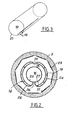
- a device comprises a sealed enclosure 1 with a horizontal axis XX comprising a first cylindrical part 2 around which are arranged heating means 3. These heating means 3 are mounted movable along the axis XX with respect to to said enclosure so as to disengage the first cylindrical part 2 from the latter and thus give access to this cylindrical part.
- the enclosure 1 also comprises a second cylindrical part 4 to which the first cylindrical part 2 is removably fixed so that this first cylindrical part can be moved horizontally to release the elements which are arranged inside of it.
- the heating means 3 are constituted by an inductor connected to a high frequency generator, by an oven heated by resistance or by means of heating by radiation. These heating means are conventionally controlled to regulate the temperature of the first part of the enclosure.
- a substrate holder 5 having a cylindrical outer wall is made integral with a member cylindrical 6 by means of metal rods 7 also removably fixed thereon, at 8.
- the substrate holder 5 can advantageously consist of graphite coated or not coated with silicon carbide.
- This shaft 12 is connected to appropriate mechanical means which can be constituted by any known drive means, so as to impart a rotational movement to the assembly.
- the device according to the invention also comprises a gas injector-ejector 14, one end of which is placed inside the substrate holder and the other end of which is fixed to the second cylindrical part 4 of the enclosure. It should be noted that this gas injector-ejector passes through the cylindrical member 6 on which the substrate holder is fixed 5. It should also be noted that this gas injector-ejector has a generally cylindrical shape and is coaxial with the holder. substrates.
- This injector-ejector has, at its end opposite to its end disposed inside the substrate holder 5, means 15 of known type allowing the introduction of reactive mixtures 16 inside this gas injector and ejector and at inside a reactive space 17 as will be described in more detail below, this reactive space being further delimited by the substrate holder 5 and the gas injector-ejector 14.
- these means 15 also make it possible to pump gases 18 from this reactive space and to circulate a cooling fluid 19, as will be described later, inside the injector-ejector.
- the part of this injector-ejector 14 disposed inside the substrate holder 5 comprises two flanges 20 and 21 delimiting, with the substrate holder 5 and the corresponding cylindrical part of the injector-ejector, the reaction space 17 in which the treatment will take place and optionally a passage of additional reducing or inert gas introduced beyond the flange 21 into the first cylindrical part of the enclosure, this gas then being discharged through an opening 20a formed in the second cylindrical part of this one.
- the flanges 20 and 21 are independent of the gas injector-ejector 14. These flanges are then fixed to the substrate holder 5 which is in this case completely closed at its end opposite to that by which the gas injector-ejector enters this substrate holder. It should be noted that a pressure gauge 22 can also be provided on the second cylindrical part of the enclosure so as to determine the pressure prevailing inside it.
- first part of the enclosure one of the ends of which communicates with the second part thereof, is closed at its other end.
- the device comprises means which are usually encountered in this kind of apparatus and which are not shown in this figure.
- These means may consist, for example, of a device for regulating the temperature of the heating means 3 or of the substrate holder 5, a system for measuring and regulating gas flow rates, a trapping and pumping system associated with regulation. pressure controlled by the gauge 22 and various accessories of known type necessary for the use of dangerous gases in chemical deposition devices.
- the end of the first cylindrical part of the enclosure communicates with a loading station making it possible to handle and load the substrates on the substrate holder, as will be described later.
- the substrate holder 5 has a cylindrical outer wall and a prismatic inner wall so as to be able to support planar substrates 23 on each of its faces.
- the gas injector-ejector 14 comprises an outer cylinder 24 and an inner cylinder 25.
- the inner cylinder 25 through which the reactive mixture 16 arrives has a series of openings 26 formed on the lowest generatrix of said inner cylinder through which the reactive mixture is introduced into the reactive space 17.
- the outer cylinder 24 has a flared portion 27 extending these openings in the direction of the reactive space.
- the outer cylinder 24 also has a series of openings 28 formed on the generator the highest of this cylinder and allowing the evacuation of the reactive mixture 18 from the reactive space 17.
- This external cylinder also comprises channels 29 in which a coolant 19 circulates.
- An embodiment of such a device made it possible to position nine substrates of 76.2 mm in diameter in a polygon inscribed in a circle of 25 cm in diameter.
- Different and especially larger diameters can be used without departing from the scope of the invention.
- the diameter of the injector-ejector is obviously modified accordingly.
- the invention makes it possible to significantly increase the yield in reagent transformed into solid compared to known techniques where the positions are not equivalent and this without affecting the homogeneity of the layers of substrate to substrate.
- the flow of the gaseous phase takes place on the same substrate in two opposite directions at each turn, corresponding to the ascending and descending phases of the substrate, which allows, with the addition in general not necessary d '' a control of the deposition speed in front of the injector, to perfectly homogenize the thickness deposited on each substrate.
- a high mass transfer in the gas phase is obtained in front of the jet when a surface is placed at a distance from the jet such as it is located in the zone where the gas speed is preserved when there is no 'obstacle.
- the distance between the openings 26 and the substrates is greater than 25 times the diameter of these openings so as to minimize be the transfer in front of the jet. This is also necessary to deposit monocrystalline layers in front of it.
- the jet of reactive mixture is broken by the interposition of an obstacle opposite the openings of the cylinder 25 and this obstacle can be constituted by an uncooled tube allowing for example to bring a gas of the PH ] type, in the reagent space, so as to heat it before it is mixed with the other reagents.
- Homogeneous injection over the entire length of the reaction space is based on the same operating principles as the main injector.
- the central injector is composed of two concentric cylinders arranged one inside the other.
- the internal cylinder makes it possible to inject the gases into an annular space situated between the two cylinders, by means of a series of openings having the same characteristics as the openings 26 mentioned above, but arranged along the highest generatrix of the inner cylinder.
- the gases then exit the annular space through a rectangular window of small width of one to a few millimeters, centered on the lowest generatrix of the inner cylinder.
- the uniformity of the injection of gases into the reaction space is then improved and the speed of the gases leaving the injector is all the more reduced the larger the rectangular window, thus avoiding the effect of " multi-jets "obtained with the device in Fig.2.
- the openings 26 are formed on the lower generatrix of the inner cylinder 25. These openings are wind present, as already described, the same diameter along the injector. However, according to another embodiment, this diameter increases when one approaches the end of the gas injector-ejector furthest from the inlet of reactive mixture 16.
- openings can also be constituted by holes, optionally drilled in a massive bar welded inside the cylinder so that the length / diameter ratio of the openings is equal to or greater than 2.
- the diameters of the cylinders constituting the injector-ejector and of the openings 26 are such that the ratio between the area of the section of the cylinder and the sum of the areas of the sections of the openings is as large as possible, and always at least greater than 2.
- the ratio of the two surfaces is 80 .
- this ratio is 40.
- a lower ratio can be used provided that the diameter of the openings is increased, as already described.
- the gas flow ejected along the cylinder must be uniform.
- the evacuation of gases from the reaction space 17 is carried out according to the same principle as injection, through a series of openings 28. This evacuation gases are carried out by means of a conventional pumping device.
- the coolant 19 is conveyed in the channels 29 and, after having made one or more paths in these channels arranged around the outer cylinder 24, is evacuated so as to ensure good temperature uniformity over the entire length of the outer wall of the injector-ejector.
- a low temperature gradient can be established along a half-circumference of the outer wall thereof, so as to produce a natural convection along this wall in the same direction as the forced convection in the reaction space 17 .
- various liquids are conventionally used, including water at the lowest temperatures. It is also advantageous to use relatively high temperatures of the external wall of the injector-ejector which can go up to a value of about 200 * lower than the temperature of the substrate holder so that the kinetics of the chemical reactions at the level of the injector is slow enough to be neglected in relation to the chemical kinetics in the reactive space and on the surface of the substrates.
- the outer wall of the assembly is then the wall of the cylinder 24 connected to the pumping device and the cooling is ensured in the central part of the injector-ejector optionally without direct contact with the walls of the cylinder 25 constituting the injector. in the hot zone of the device.
- the entire device thus makes it possible to best choose and control the temperature gradient in the reaction space 17.
- the injection of fresh gas being carried out in the lower part of this natural convection assists the upward flow by forced convection.
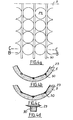
- FIG. 4a represents a development of the internal prismatic surface of the substrate holder 5 with the circular substrates 23 and a nonlimiting example of devices making it possible to maintain these substrates on the substrate holder.
- These holding devices can for example be constituted by strips 30 fixed on the substrate holder to retain the substrates in position.
- Figs. 4b and 4c show two sectional views of the substrate holder in which it can be seen that the strips 30 are arranged in grooves made for this purpose between each face thereof.
- Fig. 4d shows a view on an enlarged scale of the strip 30 allowing the fixing of the substrates 23 on the substrate holder.
- the substrate holder 5 as shown in FIG. 2 is in one piece. In this case, its length is equal to or less than about twice the diameter of the cylinder in which the polygon is inscribed so as to facilitate the loading of the substrates. As shown in Figs. 3 and 4, for example five rows of nine substrates 76.2 mm in diameter are positioned in a prism which fits into a cylinder 25 cm in diameter.
- the substrate holder is composed of an outer cylindrical part on the inner surface of which are removably fixed support plates for the substrates corresponding to the n faces of the inner prism.
- the substrates can then be loaded onto these plates outside the substrate holder, these pla ques then being replaced inside the cylindrical part thereof.
- the loading of the substrates on the plates can for example be carried out in a loading station, as described above, connected to one of the ends of said enclosure.
- the heating means 3 have an opening at each end and the enclosure is extended to communicate with this loading station either of a single-piece substrate holder or of removable plates which will then be replaced therein.
- This station is designed in such a way that the enclosure can be isolated and that it cannot be vented between two deposition operations.
- the gas injector-ejector 14 of generally cylindrical shape is coaxial with the substrate holder.
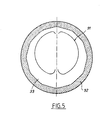
- a gas injector-ejector 31 shown diagrammatically in FIG. 5 is mounted movable vertically in a substrate holder 32.
- the injector-ejector 31 is then mounted movable in a vertical plane passing through the center of the gas injection and pumping openings, so that its height in the substrate holder.
- the gas flow speed in a reaction space 33, between the injector-ejector 31 and the substrate holder 32 increases with the distance traveled in this reaction space, from the entry of the gases by the openings in the lowest generator of the injection cylinder, until the evacuation of these gases through the openings on the highest generator of the ejection cylinder.
- composition of the reactive gas mixture can thus be deposited by changing the composition of the reactive gas mixture and possibly the total pressure and the temperature of the substrates.
- changes in composition of the reactive gas mixture are carried out, for example, after the introduction into the reactive space of a reducing or inert gas alone and / or after a pumping operation as described.
- the total pressure in the reactive space is at most equal to atmospheric pressure and the temperature of the coated substrates is kept constant by regulating the temperature of the heating means.
- the invention finds its application particularly in chemical deposits, the process of which is mainly controlled by transfer in the gas phase, that is to say the deposition of the epitaxial layers.
- the invention also finds its application in the deposition of the latter from organometallics and hydrides whereas conventional reactors do not allow sufficient homogeneity to be obtained over large areas.
- the invention applies to chemical deposits, the process of which is controlled at least in part by heterogeneous kinetics, that is to say the deposition of polycrystalline layers.
- heterogeneous kinetics that is to say the deposition of polycrystalline layers.
- polycrystalline silicon from silane but also refractory metals, silicides, nitrides, borides, oxides, etc.
Landscapes
- Chemical & Material Sciences (AREA)
- Chemical Kinetics & Catalysis (AREA)
- General Chemical & Material Sciences (AREA)
- Engineering & Computer Science (AREA)
- Materials Engineering (AREA)
- Metallurgy (AREA)
- Organic Chemistry (AREA)
- Crystallography & Structural Chemistry (AREA)
- Mechanical Engineering (AREA)
- Chemical Vapour Deposition (AREA)
Priority Applications (1)
| Application Number | Priority Date | Filing Date | Title |
|---|---|---|---|
| AT86402040T ATE53073T1 (de) | 1985-09-23 | 1986-09-17 | Verfahren und vorrichtung zur bildung eines duennen films durch abscheidung aus der gasphase auf mehreren substratflaechen. |
Applications Claiming Priority (2)
| Application Number | Priority Date | Filing Date | Title |
|---|---|---|---|
| FR8514074 | 1985-09-23 | ||
| FR8514074A FR2587731B1 (fr) | 1985-09-23 | 1985-09-23 | Procede et dispositif de depot chimique de couches minces uniformes sur de nombreux substrats plans a partir d'une phase gazeuse |
Publications (2)
| Publication Number | Publication Date |
|---|---|
| EP0223629A1 true EP0223629A1 (de) | 1987-05-27 |
| EP0223629B1 EP0223629B1 (de) | 1990-05-23 |
Family
ID=9323154
Family Applications (1)
| Application Number | Title | Priority Date | Filing Date |
|---|---|---|---|
| EP86402040A Expired - Lifetime EP0223629B1 (de) | 1985-09-23 | 1986-09-17 | Verfahren und Vorrichtung zur Bildung eines dünnen Films durch Abscheidung aus der Gasphase auf mehreren Substratflächen |
Country Status (4)
| Country | Link |
|---|---|
| EP (1) | EP0223629B1 (de) |
| AT (1) | ATE53073T1 (de) |
| DE (1) | DE3671483D1 (de) |
| FR (1) | FR2587731B1 (de) |
Cited By (3)
| Publication number | Priority date | Publication date | Assignee | Title |
|---|---|---|---|---|
| US4848272A (en) * | 1986-12-09 | 1989-07-18 | Nippon Kokan Kabushiki Kaisha | Apparatus for forming thin films |
| US4858558A (en) * | 1988-01-25 | 1989-08-22 | Nippon Kokan Kabushiki Kaisha | Film forming apparatus |
| EP0330708A1 (de) * | 1988-02-29 | 1989-09-06 | Nippon Kokan Kabushiki Kaisha | Vorrichtung zur Herstellung von dünnen Filmen |
Families Citing this family (1)
| Publication number | Priority date | Publication date | Assignee | Title |
|---|---|---|---|---|
| JP3129236B2 (ja) * | 1996-07-15 | 2001-01-29 | 住友電気工業株式会社 | 円筒形容器内流体の対流抑制方法 |
Citations (6)
| Publication number | Priority date | Publication date | Assignee | Title |
|---|---|---|---|---|
| GB768733A (en) * | 1954-10-19 | 1957-02-20 | Ohio Commw Eng Co | Improvements in and relating to plating by the decomposition of gaseous metal-bearing compounds |
| US3384049A (en) * | 1966-10-27 | 1968-05-21 | Emil R. Capita | Vapor deposition apparatus including centrifugal force substrate-holding means |
| DE2220807A1 (de) * | 1971-04-30 | 1972-11-16 | Texas Instruments Inc | Verfahren und Vorrichtung zum Abscheiden von polykristallinen Duennfilmen aus Silicium und Siliciumdioxid auf Halbleitersubstraten |
| US4096822A (en) * | 1975-09-29 | 1978-06-27 | Nippondenso Co., Ltd. | Gaseous atmosphere control apparatus for a semiconductor manufacturing system |
| FR2446327A1 (fr) * | 1979-01-09 | 1980-08-08 | Fours Indls Cie | Procede de traitement thermochimique de la paroi interne de corps ouverts a deux bouts par bombardement ionique, et dispositif pour la mise en oeuvre |
| EP0131208A1 (de) * | 1983-07-08 | 1985-01-16 | Ultra Carbon Corporation | Suszeptor-Anordnung |
Family Cites Families (1)
| Publication number | Priority date | Publication date | Assignee | Title |
|---|---|---|---|---|
| JPS59107071A (ja) * | 1982-12-12 | 1984-06-21 | Nitto Kohki Co Ltd | 被処理物の外表面にスパッタリング膜を形成する装置 |
-
1985
- 1985-09-23 FR FR8514074A patent/FR2587731B1/fr not_active Expired
-
1986
- 1986-09-17 DE DE8686402040T patent/DE3671483D1/de not_active Expired - Lifetime
- 1986-09-17 AT AT86402040T patent/ATE53073T1/de not_active IP Right Cessation
- 1986-09-17 EP EP86402040A patent/EP0223629B1/de not_active Expired - Lifetime
Patent Citations (6)
| Publication number | Priority date | Publication date | Assignee | Title |
|---|---|---|---|---|
| GB768733A (en) * | 1954-10-19 | 1957-02-20 | Ohio Commw Eng Co | Improvements in and relating to plating by the decomposition of gaseous metal-bearing compounds |
| US3384049A (en) * | 1966-10-27 | 1968-05-21 | Emil R. Capita | Vapor deposition apparatus including centrifugal force substrate-holding means |
| DE2220807A1 (de) * | 1971-04-30 | 1972-11-16 | Texas Instruments Inc | Verfahren und Vorrichtung zum Abscheiden von polykristallinen Duennfilmen aus Silicium und Siliciumdioxid auf Halbleitersubstraten |
| US4096822A (en) * | 1975-09-29 | 1978-06-27 | Nippondenso Co., Ltd. | Gaseous atmosphere control apparatus for a semiconductor manufacturing system |
| FR2446327A1 (fr) * | 1979-01-09 | 1980-08-08 | Fours Indls Cie | Procede de traitement thermochimique de la paroi interne de corps ouverts a deux bouts par bombardement ionique, et dispositif pour la mise en oeuvre |
| EP0131208A1 (de) * | 1983-07-08 | 1985-01-16 | Ultra Carbon Corporation | Suszeptor-Anordnung |
Non-Patent Citations (2)
| Title |
|---|
| PATENTS ABSTRACTS OF JAPAN, vol. 10, no. 31 (C-327)[2088], 6 février 1986; & JP-A-60 184 679 (NIPPON DENSHIN DENWA KOSHA) 20-09-1985 * |
| PATENTS ABSTRACTS OF JAPAN, vol. 8, no. 222, (C-246)[1659], 9 octobre 1984; & JP-A- 59 107 071 (NITSUTOU KOUKE) 21-06-1984 * |
Cited By (3)
| Publication number | Priority date | Publication date | Assignee | Title |
|---|---|---|---|---|
| US4848272A (en) * | 1986-12-09 | 1989-07-18 | Nippon Kokan Kabushiki Kaisha | Apparatus for forming thin films |
| US4858558A (en) * | 1988-01-25 | 1989-08-22 | Nippon Kokan Kabushiki Kaisha | Film forming apparatus |
| EP0330708A1 (de) * | 1988-02-29 | 1989-09-06 | Nippon Kokan Kabushiki Kaisha | Vorrichtung zur Herstellung von dünnen Filmen |
Also Published As
| Publication number | Publication date |
|---|---|
| ATE53073T1 (de) | 1990-06-15 |
| EP0223629B1 (de) | 1990-05-23 |
| DE3671483D1 (de) | 1990-06-28 |
| FR2587731A1 (fr) | 1987-03-27 |
| FR2587731B1 (fr) | 1988-01-08 |
Similar Documents
| Publication | Publication Date | Title |
|---|---|---|
| EP0242898B1 (de) | Vorrichtung mit flachem Suszeptor, der parallel zu einer Referenzfläche um eine Achse lotrecht zu dieser Fläche rotiert | |
| EP0119126B1 (de) | Verfahren und Vorrichtung zur Herstellung von abwechselnden monomolekularen Schichten | |
| EP0334433A1 (de) | Epitaxiereaktor mit Planetenbewegung | |
| BE1008560A3 (fr) | Dispositif et procede pour former un revetement par pyrolyse. | |
| FR2545007A1 (fr) | Procede et dispositif pour le revetement d'une piece par projection de plasma | |
| FR2571543A1 (fr) | Suscepteur a utiliser pour le depot d'une couche sur une plaquette de silicium par un procede de depot en phase vapeur | |
| FR2821859A1 (fr) | Procede pour la densification par infiltration chimique en phase vapeur de substrats poreux ayant un passage central | |
| EP0231544B1 (de) | Reaktionskammer für Epitaxiekristallzüchtung aus gasförmiger Phase von Halbleitermaterialien | |
| WO2012013869A1 (fr) | Réacteur de dépôt chimique en phase gazeuse amélioré | |
| FR2510616A1 (fr) | Appareil de production de corps cristallins tubulaires | |
| EP3808869A1 (de) | Verdampfungszelle für eine vakuumverdampfungskammer, und entsprechendes verdampfungsverfahren | |
| EP1049820B9 (de) | Verfahren zur kristallzüchtung auf einem substrat | |
| EP0223629B1 (de) | Verfahren und Vorrichtung zur Bildung eines dünnen Films durch Abscheidung aus der Gasphase auf mehreren Substratflächen | |
| FR2502643A1 (fr) | Appareil et procede de depot par jet moleculaire sur plusieurs substrats | |
| FR2573917A1 (fr) | Appareil et procede de depot a la vapeur pour la realisation de semi-conducteurs | |
| EP0371065A1 (de) | Reaktor zur oberflächenbeschichtung oder -behandlung. | |
| FR2678956A1 (fr) | Dispositif et procede de depot de diamant par dcpv assiste par plasma microonde. | |
| EP0743377A1 (de) | Vorrichtung zur chemischen Oberflächenbehandlung eines flachen Substrates mittels aktiver Gase | |
| FR2727693A1 (fr) | Reacteur pour le depot de couches minces en phase vapeur (cvd) | |
| EP0036360A1 (de) | Verfahren zur Züchtung eines Einkristalls in einem rohrförmigen, geschlossenen Gefäss | |
| FR2579487A1 (fr) | Appareil pour reguler l'ecoulement de particules fines | |
| FR2463203A1 (fr) | Creuset perfectionne pour la croissance de corps cristallins | |
| FR2545985A1 (fr) | Dispositif pour l'introduction et le retrait de semi-conducteurs dans un four | |
| CH505648A (fr) | Appareil pour la fabrication d'une matière semi-conductrice | |
| FR2604297A1 (fr) | Reacteur de depot de silicium dope |
Legal Events
| Date | Code | Title | Description |
|---|---|---|---|
| PUAI | Public reference made under article 153(3) epc to a published international application that has entered the european phase |
Free format text: ORIGINAL CODE: 0009012 |
|
| AK | Designated contracting states |
Kind code of ref document: A1 Designated state(s): AT BE CH DE GB IT LI LU NL SE |
|
| 17P | Request for examination filed |
Effective date: 19870916 |
|
| 17Q | First examination report despatched |
Effective date: 19890224 |
|
| GRAA | (expected) grant |
Free format text: ORIGINAL CODE: 0009210 |
|
| AK | Designated contracting states |
Kind code of ref document: B1 Designated state(s): AT BE CH DE GB IT LI LU NL SE |
|
| PG25 | Lapsed in a contracting state [announced via postgrant information from national office to epo] |
Ref country code: IT Free format text: LAPSE BECAUSE OF FAILURE TO SUBMIT A TRANSLATION OF THE DESCRIPTION OR TO PAY THE FEE WITHIN THE PRE;WARNING: LAPSES OF ITALIAN PATENTS WITH EFFECTIVE DATE BEFORE 2007 MAY HAVE OCCURRED AT ANY TIME BEFORE 2007. THE CORRECT EFFECTIVE DATE MAY BE DIFFERENT FROM THE ONE RECORDED.SCRIBED TIME-LIMIT Effective date: 19900523 Ref country code: AT Effective date: 19900523 Ref country code: NL Effective date: 19900523 Ref country code: SE Effective date: 19900523 Ref country code: GB Effective date: 19900523 |
|
| REF | Corresponds to: |
Ref document number: 53073 Country of ref document: AT Date of ref document: 19900615 Kind code of ref document: T |
|
| REF | Corresponds to: |
Ref document number: 3671483 Country of ref document: DE Date of ref document: 19900628 |
|
| PG25 | Lapsed in a contracting state [announced via postgrant information from national office to epo] |
Ref country code: CH Effective date: 19900930 Ref country code: LU Free format text: LAPSE BECAUSE OF NON-PAYMENT OF DUE FEES Effective date: 19900930 Ref country code: BE Effective date: 19900930 Ref country code: LI Effective date: 19900930 |
|
| NLV1 | Nl: lapsed or annulled due to failure to fulfill the requirements of art. 29p and 29m of the patents act | ||
| GBV | Gb: ep patent (uk) treated as always having been void in accordance with gb section 77(7)/1977 [no translation filed] | ||
| PLBE | No opposition filed within time limit |
Free format text: ORIGINAL CODE: 0009261 |
|
| STAA | Information on the status of an ep patent application or granted ep patent |
Free format text: STATUS: NO OPPOSITION FILED WITHIN TIME LIMIT |
|
| BERE | Be: lapsed |
Owner name: CENTRE NATIONAL DE LA RECHERCHE SCIENTIFIQUE CNRS Effective date: 19900930 |
|
| 26N | No opposition filed | ||
| REG | Reference to a national code |
Ref country code: CH Ref legal event code: PL |
|
| PG25 | Lapsed in a contracting state [announced via postgrant information from national office to epo] |
Ref country code: DE Effective date: 19910601 |