EP0223634A1 - Gasbrenner der Gas/Luftvormischungsbauart - Google Patents
Gasbrenner der Gas/Luftvormischungsbauart Download PDFInfo
- Publication number
- EP0223634A1 EP0223634A1 EP86402130A EP86402130A EP0223634A1 EP 0223634 A1 EP0223634 A1 EP 0223634A1 EP 86402130 A EP86402130 A EP 86402130A EP 86402130 A EP86402130 A EP 86402130A EP 0223634 A1 EP0223634 A1 EP 0223634A1
- Authority
- EP
- European Patent Office
- Prior art keywords
- grid
- box
- orifices
- burner
- slots
- Prior art date
- Legal status (The legal status is an assumption and is not a legal conclusion. Google has not performed a legal analysis and makes no representation as to the accuracy of the status listed.)
- Granted
Links
Images

Classifications
-
- F—MECHANICAL ENGINEERING; LIGHTING; HEATING; WEAPONS; BLASTING
- F23—COMBUSTION APPARATUS; COMBUSTION PROCESSES
- F23D—BURNERS
- F23D14/00—Burners for combustion of a gas, e.g. of a gas stored under pressure as a liquid
- F23D14/46—Details
- F23D14/48—Nozzles
- F23D14/58—Nozzles characterised by the shape or arrangement of the outlet or outlets from the nozzle, e.g. of annular configuration
-
- F—MECHANICAL ENGINEERING; LIGHTING; HEATING; WEAPONS; BLASTING
- F23—COMBUSTION APPARATUS; COMBUSTION PROCESSES
- F23D—BURNERS
- F23D14/00—Burners for combustion of a gas, e.g. of a gas stored under pressure as a liquid
- F23D14/02—Premix gas burners, i.e. in which gaseous fuel is mixed with combustion air upstream of the combustion zone
- F23D14/04—Premix gas burners, i.e. in which gaseous fuel is mixed with combustion air upstream of the combustion zone induction type, e.g. Bunsen burner
- F23D14/10—Premix gas burners, i.e. in which gaseous fuel is mixed with combustion air upstream of the combustion zone induction type, e.g. Bunsen burner with elongated tubular burner head
Definitions
- the present invention relates to a burner of the gas / air premix type.
- premixed and atmospheric induction burners with partitioned outlet section are known, the relatively simple manufacture of which allows the multiplication of heating points in a hearth.
- Such burners are commonly used for domestic use, for example water heaters or restaurant hobs, and are often arranged in the form of a ramp.
- it has the drawbacks of having a low specific power in relation to their size, and of giving rise to flames which can sometimes be unstable.
- their adjustments are delicate and they can, in practice, operate with satisfactory yields only for a determined feeding regime, which most often requires regulation everywhere or nothing.
- the gas / air premix burner according to the present invention makes it possible to solve the difficulties mentioned in the prior art by creating a burner of simple, robust construction, of small size, and making it possible to modulate the heat flow, thanks to its large flexibility of operation, and deliver significant specific power.
- the gas burner according to the invention of the gas / air premix type feeds a distribution box comprising at least one flame ramp, and is characterized in that it is composed of a stacked structure comprising : - said distribution box which has an elongated, flattened shape, and receives, above it, a grid of flames, in the form of a thin plate, formed with at least one series of orifices which communicate with the interior volume of said box and which are regularly distributed around the periphery of said grid and at least along its length, said orifices being in the form of slots formed in at least one of the two faces of said plate, and said grid receiving, above it, - At least one plate of reduced thickness forming a cap from the cap.
- At least some of the orifices forming slots have, on at least one of said faces, a substantially rectangular section which widens in the direction of flow of the gas mixture, forming an expansion chamber.
- the speed of flow of the combustible mixture through the slots undergoes a relative decrease, which promotes the stability and the attachment of the flames, thus improving the flexibility of operation of the burner.
- the grid has an upper face and a lower face, the slots formed on the upper face having a substantially rectangular and constant section, while that the rectangular section slots which widens in the direction of flow of the mixture, are formed on the underside.
- such burners are, as mentioned above, of particularly simple construction, of small size, have a high specific power. and remarkable flexibility of use.
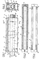
- a burner according to the invention, identified as a whole 1 and which is constituted by a housing 2 forming a distribution box in which is disposed a supply tube 3 as a combustible gas mixture, which tube is pierced with orifices 33, 43 through which said combustible mixture flows towards a grid 4 on which slots 5, 6 are formed; said grid being capped with a plate 7 forming a cap.
- the tube 3 can in particular be screwed, towards the inlet end 23, and substantially in the axis 63 of the box, on the inner wall of the tubular part 53 projecting from said box.
- the combustible gas mixture (gas / air) which feeds the burner 1 comes from a premix chamber (not shown) connected to the feed tube 3, towards the end 23, via a distribution sheath (not shown).
- the distribution box 2 has an elongated shape, relatively flattened and of section substantially in "U" shape. It can in particular be manufactured in a foundry or by stamping, thus offering an embodiment which is both simple and inexpensive.
- the free interior volume forming chamber 12 of the box communicates, through a passage or an elongated slot 22 with the grid 4 and the cap 7.
- the cohesion of the stacked structure formed by the burner 1 can be ensured by screws which successively link the constituent elements of the burner.
- This type of assembly being known, only the locations 11 of the screws are advantageously located towards the ends of the burner.
- the grid 4 is in the form of a plate, preferably metallic substantially rectangular and thin (of the order of a centimeter).
- this grid are formed series of orifices 5, 6 advantageously formed in slots and which communicate with the internal volume 12 of the box 2.
- this communication is ensured by an opening 34 formed towards the central part of the grid and which thus forms a passage between the interior volume 12 and the plate 7 forming a cap; said opening being disposed opposite passage 22 formed in box 2.
- the slots 5, 6 are provided, respectively, on each of the opposite faces 14, 24 of Grid .
- the slots 5 have a substantially rectangular and constant section, while the slots 6 have a section which is initially rectangular but widens in the direction of flow of the gas mixture, forming expansion chamber 16; said slots 6 having a depth less than that of slots 5, and all being substantially of the same section.
- the slots 5 and 6 are distributed substantially regularly at the periphery and along the length of the grid 4 opposite the passage 34. L orientation of the slots 5 and 6 is such that they are formed substantially perpendicularly on either side of the longitudinal axis 44 of the support grid 4. In addition, the slots 5 and 6 are preferably of the same number .
- the burner 1 When the burner 1 is placed in its optimal operating position, that is to say substantially horizontally so that the constituent elements of the burner form a stacked structure based on the box 2 which receives, above it, the grid 4 capped with its cap 7, the slots 5 are arranged on the upper face 14 of the grid; the slots 6 then being formed symmetrically on the underside 24 thereof.
- the diffuser tube 3 the end opposite to the inlet is closed by a wall, is supplied with a gaseous mixture (gas / air) and is provided with orifices 33 , 43.
- gaseous mixture gas / air
- orifices 33 , 43 are substantially regularly distributed in two series 33, and 43 along the major part of said tube. More specifically and advantageously, the orifices of each of the series are distributed linearly and substantially parallel to the longitudinal axis 13 of the tube 3; each series of orifices being further apart angularly about 90 °.
- the orifices are directed towards the bottom 42, from the box (2).
- the orifices 33, 43 of the distributor tube are arranged so that the first orifice is disposed, relative to the wall of the box towards its end d admission 23, at a distance of the order of twice the distance separating two successive orifices, the last orifice being disposed, with respect to the opposite wall 23 ′ of the box, at a distance of the order of four times this gap.
- the cap 7 which covers the slots 5 of the grid 4 can be in the form of a rectangular metal plate of small thickness and whose dimensions are substantially those of the covered grid.
- the cap plate 7 can, for example, be made of copper.
- the burner of the invention delivers its optimum nominal power and offers its best operating flexibility
- the grid 4 is surmounted by a part 27, and a cap 17 having a wall 28 formed back, for example a few millimeters; the intermediate part 27, in the form of a flat plate, coming to be inserted between the grid 4 and the cap 17.
- This hat is in the form of substantially a thin rectangular plate whose dimensions are substantially equal to those of the grid that it covers.
- the wall 28 of the cap 17 is formed back from its face 18 directed towards the grid. This wall extends over the entire width of the plate 17 forming a cap and over most of its length.
- the intermediate piece 27 comprises, towards its central part, an oblong longitudinal slot 38, which extends over most of the length of the intermediate plate and passes through it over its entire thickness.
- the slot 38 is arranged opposite the passage 22 of the box 2 and the communication slot 34 of the grid 4.
- This intermediate piece 27 can optionally be omitted; the grid 4 is no longer then capped only by the cap 17 or else, as shown in FIG. 1, by the cap in the form of a flat plate 7 whose thickness is substantially constant.
- the combined use of the cap 17 and the intermediate plate 27 leads to an improvement in the calorific power delivered of the order of 10%.
- the burner which has just been described operates as follows: - the distributor tube 3 of the burner 1 is supplied with premix.
- This air / gas premix can be carried out using a mixer of any known type.
- the air necessary for combustion is induced by the gas pressure, thus achieving the stoichiometric mixture.
- This mixture is then distributed inside the box 2 in the internal volume 12, forming a distribution chamber, via the tube 3 in which the orifices 33, 43 are pierced.
- the gas mixture then flows towards the grid 4, the communication passage 22 ensuring its flow from the interior volume 12 to the slots 5, 6 of the grid 4.
- the flow rate of the gaseous mixture which ignites thanks to the igniter (not shown) provided for this purpose, is distributes substantially uniformly over the length of the grid, in the upper 5 and lower 6 slots, the flames catching on the outside of the burner, near said slots.
- the slots 6 can in particular play the role, thanks to their expansion chamber 16, for controlling the flames; the main flames of the burner then being attached to the outside of the slots 5.
- a burner according to the invention may, in particular, include a box 2 whose internal volume 12 of distribution of the mixture is of the order of 150 to 250 cm3 and preferably equal to approximately 200 cc.
- the distributor tube 3 is advantageously provided with 26 orifices 33, 43, distributed in two series of 13 and pierced at an apex angle of about 90 °; said holes having a diameter of the order of 3 mm and being substantially regularly separated by a distance of approximately 15 mm.
- a good distribution of the gaseous mixture, over the length of the burner, is ensured when the first hole in each series is housed about 30 mm from the internal wall limiting the interior volume of said box, towards its inlet 23; the last hole being made about 60 mm from the opposite internal wall, towards the end 23 ′.
- the upper slots 5 may be 2 ⁇ 55, and with a rectangular section of the order of 2 ⁇ 3 mm; the lower slots 6, of the same number, having first a rectangular section of approximately 2 ⁇ 1.2 mm and then, at the outlet of the expansion chamber 16, a section of approximately 4 ⁇ 1.2 mm.
- the burner that we have just presented can deliver a nominal power of the order of 40 kW / PCS by being supplied under admosphetic induction with natural gas at a pressure of about 0.1 to 1.2 bar, or with gas of liquefied petroleum under a pressure ranging from approx. ron 0.1 to 0.7 bar.
- the power delivered is important.
- the flexibility of operation of such a burner allows a modification of the specific power delivered in a ratio of the order of 1 to 20. This makes it possible to design devices for producing heat at low temperature, in particular boilers with distill spirits. At the same time, the good distribution of the heat flow allows the application of such burners, in particular for the heating of molds used in foundries or for the manufacture of ceramics.
- a particularly advantageous use of the burner of the invention in the industrial field can result from the association of several groups of burners. It is possible in particular to provide groups of two or three burners arranged in parallel, each group having its admission in gaseous mixture and its premix chamber. The groups thus formed will then be distributed over the surfaces to be heated, thus providing a uniform distribution of the heat flow.
- an installation of this type comprising twenty four burners per series of three, can deliver a power of the order of 800 kW distributed substantially over the entire surface to be heated of a alcohol distillation tank.
- the burner is arranged and operates in the inverted position, that is to say, upside down, the stack then having the cap as a base; this configuration can further improve the efficiency of the burner in recu piercing the heat of condensation of the water vapor delivered by combustion.
- the interignition of these provision may be made for the grid 4 to include slots 15 for passage of said combustible gas mixture.
- slots are preferably arranged on the face 14 of the grate, towards the end 23 ′ of the burner opposite the inlet 23, and between the two rows of slots 5 formed on either side of the axis 44, said slots forming a corolla.
- the end part of the supply tube 3, opposite the inlet 23, can extend inside a tubular cavity 53 ′ projecting from the box 2; said tube being able to be hollow at its two ends, a plug (not shown) closing off its opposite end to the inlet, for example, by screwing on a thread provided for this purpose on the external wall of the cavity 53 ′.
Landscapes
- Engineering & Computer Science (AREA)
- Chemical & Material Sciences (AREA)
- Combustion & Propulsion (AREA)
- Mechanical Engineering (AREA)
- General Engineering & Computer Science (AREA)
- Gas Burners (AREA)
- Pre-Mixing And Non-Premixing Gas Burner (AREA)
Priority Applications (1)
| Application Number | Priority Date | Filing Date | Title |
|---|---|---|---|
| AT86402130T ATE44814T1 (de) | 1985-10-16 | 1986-09-30 | Gasbrenner der gas/luftvormischungsbauart. |
Applications Claiming Priority (2)
| Application Number | Priority Date | Filing Date | Title |
|---|---|---|---|
| FR8515337 | 1985-10-16 | ||
| FR8515337A FR2588638B1 (fr) | 1985-10-16 | 1985-10-16 | Bruleur a gaz du type a premelange gaz/air |
Publications (2)
| Publication Number | Publication Date |
|---|---|
| EP0223634A1 true EP0223634A1 (de) | 1987-05-27 |
| EP0223634B1 EP0223634B1 (de) | 1989-07-19 |
Family
ID=9323877
Family Applications (1)
| Application Number | Title | Priority Date | Filing Date |
|---|---|---|---|
| EP86402130A Expired EP0223634B1 (de) | 1985-10-16 | 1986-09-30 | Gasbrenner der Gas/Luftvormischungsbauart |
Country Status (5)
| Country | Link |
|---|---|
| EP (1) | EP0223634B1 (de) |
| AT (1) | ATE44814T1 (de) |
| DE (1) | DE3664528D1 (de) |
| ES (1) | ES2003142A6 (de) |
| FR (1) | FR2588638B1 (de) |
Cited By (2)
| Publication number | Priority date | Publication date | Assignee | Title |
|---|---|---|---|---|
| GB2208921A (en) * | 1987-08-20 | 1989-04-19 | Gas Logs | Gas burner |
| US20170209908A1 (en) * | 2016-01-27 | 2017-07-27 | David B. Smathers | Fabrication of high-entropy alloy wire and multi-principal element alloy wire |
Citations (2)
| Publication number | Priority date | Publication date | Assignee | Title |
|---|---|---|---|---|
| US2494243A (en) * | 1944-07-31 | 1950-01-10 | Louis D Houlis | Pressure ribbon-type gas burner |
| GB1222354A (en) * | 1967-03-13 | 1971-02-10 | Barter And Sons Ltd | Improvements in or relating to aerated gas burners |
Family Cites Families (1)
| Publication number | Priority date | Publication date | Assignee | Title |
|---|---|---|---|---|
| US4475885A (en) * | 1983-07-28 | 1984-10-09 | Bloom Engineering Company, Inc. | Adjustable flame burner |
-
1985
- 1985-10-16 FR FR8515337A patent/FR2588638B1/fr not_active Expired
-
1986
- 1986-09-30 AT AT86402130T patent/ATE44814T1/de not_active IP Right Cessation
- 1986-09-30 EP EP86402130A patent/EP0223634B1/de not_active Expired
- 1986-09-30 DE DE8686402130T patent/DE3664528D1/de not_active Expired
- 1986-10-15 ES ES8602607A patent/ES2003142A6/es not_active Expired
Patent Citations (2)
| Publication number | Priority date | Publication date | Assignee | Title |
|---|---|---|---|---|
| US2494243A (en) * | 1944-07-31 | 1950-01-10 | Louis D Houlis | Pressure ribbon-type gas burner |
| GB1222354A (en) * | 1967-03-13 | 1971-02-10 | Barter And Sons Ltd | Improvements in or relating to aerated gas burners |
Cited By (6)
| Publication number | Priority date | Publication date | Assignee | Title |
|---|---|---|---|---|
| GB2208921A (en) * | 1987-08-20 | 1989-04-19 | Gas Logs | Gas burner |
| US4890601A (en) * | 1987-08-20 | 1990-01-02 | Gas Logs (Brailsford) Ltd. | Gas burner |
| GB2208921B (en) * | 1987-08-20 | 1991-06-19 | Gas Logs | Gas burner |
| US20170209908A1 (en) * | 2016-01-27 | 2017-07-27 | David B. Smathers | Fabrication of high-entropy alloy wire and multi-principal element alloy wire |
| US10668566B2 (en) * | 2016-01-27 | 2020-06-02 | H.C. Starck Inc. | Fabrication of high-entropy alloy wire and multi-principal element alloy wire |
| US11198197B2 (en) | 2016-01-27 | 2021-12-14 | H.C. Starck Inc. | Fabrication of high-entropy alloy wire and multi-principal element alloy wire |
Also Published As
| Publication number | Publication date |
|---|---|
| FR2588638A1 (fr) | 1987-04-17 |
| ATE44814T1 (de) | 1989-08-15 |
| ES2003142A6 (es) | 1988-10-16 |
| EP0223634B1 (de) | 1989-07-19 |
| DE3664528D1 (en) | 1989-08-24 |
| FR2588638B1 (fr) | 1989-03-03 |
Similar Documents
| Publication | Publication Date | Title |
|---|---|---|
| EP0125965B1 (de) | Brenner für gasförmigen Brennstoff mit eingebautem Zünd- und Sicherheitssystem | |
| JP2633070B2 (ja) | ダブル・フレイム防風ライター | |
| MC325A1 (fr) | Plaques rayonnantes pour brûleurs | |
| FR2804496A1 (fr) | Bruleur a gaz a multiples couronnes de flammes | |
| BE719847A (de) | ||
| EP0751352B1 (de) | Auf einer Einspritzdüse zentrierter Kochbrenner | |
| FR2783040A1 (fr) | Bruleur a gaz pour le chauffage et/ou la cuisson d'aliments | |
| EP0223634B1 (de) | Gasbrenner der Gas/Luftvormischungsbauart | |
| EP0006774A2 (de) | Brenner für flüssige Brennstoffe | |
| BE902029A (fr) | Bruleur a gaz pour fourneaux et plans de cuisson en general. | |
| FR2561754A1 (fr) | Chambre de combustion pour appareils de chauffage | |
| FR2518708A1 (fr) | Cylindre a combustion pour appareil chauffant par rayonnement a petrole | |
| EP0679839A1 (de) | Verbesserungen an Gasbrennern | |
| CA3146685A1 (fr) | Bruleur modulaire et four comprenant ce bruleur | |
| LU88271A1 (fr) | Plaque de cuisson a rendement eleve et a combustion amelioree.x | |
| EP1172607B1 (de) | Gasbrenner mit erhöhter Leistung | |
| EP0427650A1 (de) | Mit gasförmigem Brennstoff betriebener Brenner | |
| EP1322894A1 (de) | Terrassenheizung | |
| EP0486741A1 (de) | Gasheizgerät mit Infrarotstrahlung | |
| EP0660040A1 (de) | Brennerkopf für Brenner mit niedriger Schadstoffemission und Kessel versehen mit solchen Brenner | |
| EP0679838B1 (de) | Verbesserungen an Gasbrennern | |
| EP0549416B1 (de) | Brenner mit Verbrennungsgitter und Heizungsanlage mit einem solchen Brenner | |
| FR2823557A1 (fr) | Bruleur a gaz dispose sous une plaque | |
| FR2682742A1 (fr) | Table de cuisson vitro-ceramique, chauffee au gaz. | |
| FR2745891A1 (fr) | Bruleur atmospherique a gaz a premelange total |
Legal Events
| Date | Code | Title | Description |
|---|---|---|---|
| PUAI | Public reference made under article 153(3) epc to a published international application that has entered the european phase |
Free format text: ORIGINAL CODE: 0009012 |
|
| AK | Designated contracting states |
Kind code of ref document: A1 Designated state(s): AT BE CH DE GB IT LI LU NL SE |
|
| 17P | Request for examination filed |
Effective date: 19870930 |
|
| 17Q | First examination report despatched |
Effective date: 19880718 |
|
| GRAA | (expected) grant |
Free format text: ORIGINAL CODE: 0009210 |
|
| AK | Designated contracting states |
Kind code of ref document: B1 Designated state(s): AT BE CH DE GB IT LI LU NL SE |
|
| REF | Corresponds to: |
Ref document number: 44814 Country of ref document: AT Date of ref document: 19890815 Kind code of ref document: T |
|
| ITF | It: translation for a ep patent filed | ||
| GBT | Gb: translation of ep patent filed (gb section 77(6)(a)/1977) | ||
| REF | Corresponds to: |
Ref document number: 3664528 Country of ref document: DE Date of ref document: 19890824 |
|
| PG25 | Lapsed in a contracting state [announced via postgrant information from national office to epo] |
Ref country code: LU Free format text: LAPSE BECAUSE OF NON-PAYMENT OF DUE FEES Effective date: 19890930 Ref country code: LI Effective date: 19890930 Ref country code: CH Effective date: 19890930 Ref country code: BE Effective date: 19890930 Ref country code: AT Effective date: 19890930 |
|
| PG25 | Lapsed in a contracting state [announced via postgrant information from national office to epo] |
Ref country code: SE Effective date: 19891001 |
|
| BERE | Be: lapsed |
Owner name: GAZ DE FRANCE Effective date: 19890930 |
|
| PG25 | Lapsed in a contracting state [announced via postgrant information from national office to epo] |
Ref country code: NL Effective date: 19900401 |
|
| PLBE | No opposition filed within time limit |
Free format text: ORIGINAL CODE: 0009261 |
|
| STAA | Information on the status of an ep patent application or granted ep patent |
Free format text: STATUS: NO OPPOSITION FILED WITHIN TIME LIMIT |
|
| NLV4 | Nl: lapsed or anulled due to non-payment of the annual fee | ||
| REG | Reference to a national code |
Ref country code: CH Ref legal event code: PL |
|
| PG25 | Lapsed in a contracting state [announced via postgrant information from national office to epo] |
Ref country code: DE Effective date: 19900601 |
|
| 26N | No opposition filed | ||
| PG25 | Lapsed in a contracting state [announced via postgrant information from national office to epo] |
Ref country code: GB Effective date: 19900930 |
|
| GBPC | Gb: european patent ceased through non-payment of renewal fee | ||
| EUG | Se: european patent has lapsed |
Ref document number: 86402130.8 Effective date: 19900706 |
|
| PG25 | Lapsed in a contracting state [announced via postgrant information from national office to epo] |
Ref country code: IT Free format text: LAPSE BECAUSE OF NON-PAYMENT OF DUE FEES Effective date: 20050930 |