EP0223754A2 - Vorrichtung und Verfahren zum Herstellen von aus Kunststoffgeformten Gegenständen, insbesondere Füllstutzen für Brennstofftanks von Motorfahrzeugen - Google Patents
Vorrichtung und Verfahren zum Herstellen von aus Kunststoffgeformten Gegenständen, insbesondere Füllstutzen für Brennstofftanks von Motorfahrzeugen Download PDFInfo
- Publication number
- EP0223754A2 EP0223754A2 EP86830351A EP86830351A EP0223754A2 EP 0223754 A2 EP0223754 A2 EP 0223754A2 EP 86830351 A EP86830351 A EP 86830351A EP 86830351 A EP86830351 A EP 86830351A EP 0223754 A2 EP0223754 A2 EP 0223754A2
- Authority
- EP
- European Patent Office
- Prior art keywords
- mould
- semi
- cavity
- finished tube
- figures
- Prior art date
- Legal status (The legal status is an assumption and is not a legal conclusion. Google has not performed a legal analysis and makes no representation as to the accuracy of the status listed.)
- Withdrawn
Links
- 239000000463 material Substances 0.000 title claims abstract description 25
- 239000004033 plastic Substances 0.000 title claims abstract description 21
- 229920003023 plastic Polymers 0.000 title claims abstract description 21
- 238000000034 method Methods 0.000 title claims description 8
- 239000002828 fuel tank Substances 0.000 title description 2
- 238000004519 manufacturing process Methods 0.000 claims abstract description 17
- 230000000295 complement effect Effects 0.000 claims description 17
- 238000007664 blowing Methods 0.000 claims description 4
- 230000015572 biosynthetic process Effects 0.000 claims description 2
- 230000000694 effects Effects 0.000 claims 1
- 239000002699 waste material Substances 0.000 description 9
- 239000000446 fuel Substances 0.000 description 6
- 238000000465 moulding Methods 0.000 description 6
- 239000004416 thermosoftening plastic Substances 0.000 description 4
- 230000008901 benefit Effects 0.000 description 3
- 238000000071 blow moulding Methods 0.000 description 3
- 230000005540 biological transmission Effects 0.000 description 2
- 238000001125 extrusion Methods 0.000 description 2
- 230000003313 weakening effect Effects 0.000 description 2
- 239000004959 Rilsan Substances 0.000 description 1
- 230000004323 axial length Effects 0.000 description 1
- 230000001934 delay Effects 0.000 description 1
- 239000012530 fluid Substances 0.000 description 1
- 230000009931 harmful effect Effects 0.000 description 1
- 239000007788 liquid Substances 0.000 description 1
- 230000013011 mating Effects 0.000 description 1
- 239000002184 metal Substances 0.000 description 1
- 239000011347 resin Substances 0.000 description 1
- 229920005989 resin Polymers 0.000 description 1
- 238000000926 separation method Methods 0.000 description 1
- 238000007493 shaping process Methods 0.000 description 1
Images

Classifications
-
- B—PERFORMING OPERATIONS; TRANSPORTING
- B29—WORKING OF PLASTICS; WORKING OF SUBSTANCES IN A PLASTIC STATE IN GENERAL
- B29C—SHAPING OR JOINING OF PLASTICS; SHAPING OF MATERIAL IN A PLASTIC STATE, NOT OTHERWISE PROVIDED FOR; AFTER-TREATMENT OF THE SHAPED PRODUCTS, e.g. REPAIRING
- B29C53/00—Shaping by bending, folding, twisting, straightening or flattening; Apparatus therefor
- B29C53/02—Bending or folding
- B29C53/08—Bending or folding of tubes or other profiled members
- B29C53/083—Bending or folding of tubes or other profiled members bending longitudinally, i.e. modifying the curvature of the tube axis
-
- B—PERFORMING OPERATIONS; TRANSPORTING
- B29—WORKING OF PLASTICS; WORKING OF SUBSTANCES IN A PLASTIC STATE IN GENERAL
- B29C—SHAPING OR JOINING OF PLASTICS; SHAPING OF MATERIAL IN A PLASTIC STATE, NOT OTHERWISE PROVIDED FOR; AFTER-TREATMENT OF THE SHAPED PRODUCTS, e.g. REPAIRING
- B29C49/00—Blow-moulding, i.e. blowing a preform or parison to a desired shape within a mould; Apparatus therefor
- B29C49/02—Combined blow-moulding and manufacture of the preform or the parison
- B29C49/04—Extrusion blow-moulding
-
- B—PERFORMING OPERATIONS; TRANSPORTING
- B29—WORKING OF PLASTICS; WORKING OF SUBSTANCES IN A PLASTIC STATE IN GENERAL
- B29C—SHAPING OR JOINING OF PLASTICS; SHAPING OF MATERIAL IN A PLASTIC STATE, NOT OTHERWISE PROVIDED FOR; AFTER-TREATMENT OF THE SHAPED PRODUCTS, e.g. REPAIRING
- B29C49/00—Blow-moulding, i.e. blowing a preform or parison to a desired shape within a mould; Apparatus therefor
- B29C49/42—Component parts, details or accessories; Auxiliary operations
- B29C49/4242—Means for deforming the parison prior to the blowing operation
-
- B—PERFORMING OPERATIONS; TRANSPORTING
- B29—WORKING OF PLASTICS; WORKING OF SUBSTANCES IN A PLASTIC STATE IN GENERAL
- B29C—SHAPING OR JOINING OF PLASTICS; SHAPING OF MATERIAL IN A PLASTIC STATE, NOT OTHERWISE PROVIDED FOR; AFTER-TREATMENT OF THE SHAPED PRODUCTS, e.g. REPAIRING
- B29C49/00—Blow-moulding, i.e. blowing a preform or parison to a desired shape within a mould; Apparatus therefor
- B29C49/42—Component parts, details or accessories; Auxiliary operations
- B29C49/4242—Means for deforming the parison prior to the blowing operation
- B29C49/42421—Means for deforming the parison prior to the blowing operation before laying into the mould
- B29C49/42422—Means for deforming the parison prior to the blowing operation before laying into the mould by the preform transporting means
-
- B—PERFORMING OPERATIONS; TRANSPORTING
- B29—WORKING OF PLASTICS; WORKING OF SUBSTANCES IN A PLASTIC STATE IN GENERAL
- B29C—SHAPING OR JOINING OF PLASTICS; SHAPING OF MATERIAL IN A PLASTIC STATE, NOT OTHERWISE PROVIDED FOR; AFTER-TREATMENT OF THE SHAPED PRODUCTS, e.g. REPAIRING
- B29C49/00—Blow-moulding, i.e. blowing a preform or parison to a desired shape within a mould; Apparatus therefor
- B29C49/42—Component parts, details or accessories; Auxiliary operations
- B29C49/4242—Means for deforming the parison prior to the blowing operation
- B29C49/4244—Means for deforming the parison prior to the blowing operation during or after laying preform into the final mould
- B29C49/42452—The mould opening plane being horizontal
-
- B—PERFORMING OPERATIONS; TRANSPORTING
- B29—WORKING OF PLASTICS; WORKING OF SUBSTANCES IN A PLASTIC STATE IN GENERAL
- B29L—INDEXING SCHEME ASSOCIATED WITH SUBCLASS B29C, RELATING TO PARTICULAR ARTICLES
- B29L2023/00—Tubular articles
- B29L2023/22—Tubes or pipes, i.e. rigid
Definitions
- the present invention relates to the manufacture of shaped articles of plastics material.
- the invention has been developed with particular attention to the problems inherent in the manufacture of tubular elements such as, for example, filling pipes for motor vehicle fuel tanks.
- Such tubes once made from metal, are now usually made from plastics material. They generally have one or more elbows or bends which give the tube an overall shape such as to comply with the - very strict -requirements on bulk within the motor vehicle.
- such tubes are made in the form of flexible tubes (corrugated tubes) of plastics material. This solution is unsatisfactory from at least two points of view.
- At least a portion of the filling tube of a motor vehicle tank may in fact extend within one of the wings of the motor vehicle and thus be exposed to stones and other objects accidentally thrown up from the ground by the wheels.
- the corrugations in the tube obstruct the flow of fuel to the tank.
- the corrugations particularly those closest to the end at which the fuel is introduced, constitute rebound surfaces for the fuel.
- this is introduced into the tube at a high rate of flow (for example, a flow rate of the order of 300 litres per minute) the fuel regurgitates and tends to flow out of the filling tube.
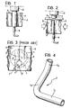
- an extruded semi-finished tube l of thermo-softening plastics material leaves the die 2 of an extruder (not illustrated in its entirety) and descends between two half-moulds 3 which are reciprocable between an open position ( Figure l) and a closed position ( Figure 2) and which, in the closed position, define a mould cavity 3' of a form corresponding to the external form of the article to be made.
- the two half-moulds 3 are brought into a mating position to enclose the semi-finished tube l between them.
- the part of the semi-finished tube l located in the mould cavity 3' is kept open and expanded by the introduction of pressurised gas into the cavity 3'.
- the mould cavity 3' typically at one of its ends
- a tube which can be seen to include: - a first straight portion T1, - a second straight portion T2 at an angle of the order 90-95° to the first portion T1, and - a third, shorter straight portion T3 at a generally obtuse angle to the straight portion T2.
- the angles between the portions T1, T2 and the portions T2, T3 respectively lie in two planes approximately perpendicular to each other.
- the moulding operation then provides for only a small part of the semi-finished tube (indicated l') intended to define the tube T remaining effectively open at the end of the moulding operation.
- the waste from the working may be recycled for use in subsequent operations.
- the waste should not be reused more than once because the material resulting from subsequent cycles of reutilisation does not enable articles of an acceptable quality to be obtained.
- Another disadvantage is due to the fact that the mass of plastics material which will be wasted has a high thermal inertia. This leads to delays in working due to the fact that, before the waste can be removed, it is necessary to wait until it has reached a temperature at which it can be handled. Furthermore, this means that the mass of waste could cause deformation of the walls of the tube T, resulting in moulding tolerances which may even be of several mm in articles having a length of the order of several tens of centimetres.
- a further disadvantage is due to the fact that the wall of the tube formed by the prior art has two joins or welds along its entire length corresponding to the regions (indicated l"' in Figure 3) in which the waste l" is separated from the tube as a result of the closure of the two half-moulds 3.
- the two half-moulds, as well as defining the cavity of the mould bring two seam-cutting projections into mutual contact to separate the tube l' from the waste l", facilitating its detachment in a subsequent operation.
- the separation effected by the half-moulds may cause weakening of the tube with the possibility of the escape of the liquid conveyed in it: in such a case the tube must be thrown away.
- the object of the present invention is to provide apparatus and a method for manufacturing shaped articles of plastics material, which do not give rise to the disadvantages expounded above.
- this object is achieved by means of apparatus for manufacturing shaped articles having at least one curve (elbow) from plastics material, in which a semi-finished tube (“parison") of softened plastics is enclosed between at least two complementary half-moulds together defining a mould cavity, characterised in that at least one of the half-moulds includes, in correspondence with the region of the mould cavity intended to define each curve of the article, a mould part which is movable between a position of introduction of the semi-finished tube in which the mould cavity is substantially straight and a final forming position in which the mould cavity has a shape which reproduces, in a complementary manner, the form of the shaped article.
- a semi-finished tube (“parison") of softened plastics is enclosed between at least two complementary half-moulds together defining a mould cavity
- at least one of the half-moulds includes, in correspondence with the region of the mould cavity intended to define each curve of the article, a mould part which is movable between a position of introduction of the semi
- the apparatus according to the invention enables the carrying out of a method (which also forms the subject of the present invention) for the manufacture of shaped articles having at least one curve from plastics material, characterised in that it includes the steps of: - providing a forming mould which, in a first position of operation, defines a substantially straight cavity, - forming a substantially straight semi-finished tube of plastics material, - introducing the semi-finished tube into the mould cavity in the first position of operation, and - deforming the mould to give the cavity a shape which reproduces, in a complementary manner, the shape of the article which is to be formed.
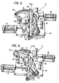
- the half-mould 3 of Figures 5 and 6 (and also its complementary half-mould not specifically illustrated in the appended drawings) comprises a base plate l0 which allows it to be installed in blow-moulding apparatus substantially the same as that already used in the prior art.
- this apparatus includes an extruder provided at the bottom with a draw-plate 2 from which an extruded semi-finished tube l of thermo-softening plastics material is discharged, in accordance with a programmed extrusion cycle, for subjection to the action of the two half-moulds 3 located beneath the draw-plate 2.
- a cutter unit such as shears 5, interposed between the draw-plate 2 and the half-moulds 3, cuts the semi-finished tube l which leaves the draw-plate 2 substantially continuously, so as to separate semi-finished pieces for use in the manufacture of shaped articles.
- the part ll is intended to form, together with the homologous part of the complementary half-mould, the portion T1 of the tube T.
- the mould parts l2 and l3, together with the homologous parts of the other half-mould, are intended respectively to form the portions T2 and T3 of the tube T.
- the part l2 (and also the complementary part of the other half-mould) is mounted in a fixed position on the plate l0.
- Each of the parts ll and l3, however, can pivot about a respective rotation axis X11, X12 to move from a first position of operation, which is illustrated in Figure 5, to a second position of operation, which is illustrated in Figure 6.
- the rotation axes of the parts ll and l3 are not parallel to each other. They are in fact perpendicular to the planes in which the angles formed by the portions T1 and T2 and T2 and T3 of the tube T lie. The choice of the relative inclinations of these planes, which depend on the shape of the article T to be formed, is substantially free.
- the movable parts ll and l3 rotate relative to the fixed part l2 so as to become located along a path corresponding to the line of extension of the tube T to be formed.
- the mould parts ll, l2 and l3 (and, as always, the homologous parts of the other half-mould) define a mould cavity which reproduces, in a complementary manner, the shape of the tube T.
- Two auxiliary mould elements or blocks l4 and l5 mounted on slide parts slidable on the plate l0 under the action of respective hydraulic or pneumatic actuators l6, l7 can advance towards the mould parts ll, l2 and l3 so as to reconstitute the continuity of the wall of the mould cavity.
- Each block l4 and l5 may be constituted by two complementary parts each slidable on one of the half-moulds 3. Alternatively, it is possible to provide blocks l4 and l5 each constituted by a single piece slidable on only one of the two half-moulds 3.
- actuators l6 and l7 which may be provided on only one of the half-moulds.
- the block parts on the other half-mould may in fact be connected (for example by pins) to the block parts mounted on the half-mould provided with the actuators, so as to ensure that they are moved without the need to provide independent drive means.
- the parts ll and l3 are fixed at one end to rotatable turrets l8 and l9 which rotate about the axes X11 and X12 under the action of a fluid motor, an electric motor or a gear transmission.
- the drive means may be provided on only one of the two half-moulds, the transmission of movement to the movable parts of the complementary half-mould being ensured through pins or like drive members.
- the movement of the blocks l4 and l5 can also be driven with the use of motor means (electric, etc.) other than the actuators l6 and l7 illustrated here.
- An appendage, indicated lla, of the part ll (a similar appendage is provided on the complementary part mounted on the other half-mould) forms an angle of about 90-95° with the body of the part ll, equal to the angle between the portions T1 and T2 of the tube 4.
- the appendage lla which extends from that end of the part ll facing the part l2, projects outwardly of the mould cavity.
- the appendage lla is in a position in which it bears against the part l2 (which has a corresponding recess) so as to complete the wall of the mould cavity.
- Another appendage l3a with a structurally similar function is provided on the movable part l3.
- Two arcuate structures 20 and 2l are fixed to the plate l0 in correspondence with the free ends of the parts ll and l2 and function as operating cams for two pusher members 22 and 23 mounted in correspondence with the free ends of the parts ll and l3 (that is, the ends opposite the turrets l8 and l9).
- the function of the members 22 and 23, which in general have a cylindrical or sleeve structure, is to exert a thrust on the ends of the semi-finished tube l introduced into the half-moulds in order to facilitate the entry of the ends of the semi-finished tube l into the mould cavity when the movable parts ll and l3 are brought into the final forming position shown in Figure 6.
- the cavity has an overall axial length less than that which the cavity itself has in the final position of the mould in Figure 6.
- the mould cavity is, so to speak,”lengthened” in correspondence with the curves of the blocks l4 and l5.
- the two ends of the semi-finished tube l are, so to speak, accompanied into the mould cavity by the pusher members 22 and 23.
- Each of these members has a pin (only the pin 23' associated with the pusher member 23 is visible in the drawings) which cooperates with the respective cam 20, 2l so that, as a result of the rotation of the part ll from the position of receiving the semi-finished tube ( Figure 5) towards the final forming position ( Figure 6), the pusher member 22, 23 is thrust into the respective movable mould part ll,l3.
- cam parts 20 and 22 may in fact be mounted on only one of the half-moulds, use then being made of either a single pusher member for each pair of homologous movable parts (ll or l3) or two complementary pusher members connected together by pins or other drive members.
- a semi-finished tube l of thermo-softening plastics material is first formed with a diameter corresponding substantially to the diameter of the tube T.
- a semi-finished tube including a mass of plastics material which is practically the same as the mass intended to constitute the finished tube T.
- the semi-finished tube l is introduced longitudinally into the two half-moulds 3 which are coupled together and in which the mould parts ll and l3 are kept in a position of alignment with the central fixed part l2.
- the semi-finished tube l is introduced into the mould cavity - which for the moment has a straight form - so that its ends project beyond the ends of the cavity itself, and the pusher members 22 and 23 are then brought into their positions of abutment against the ends of the semi-finished tube l.
- the actuators l6 and l7 are actuated so as to bring the blocks l4 and l5 against the mould parts ll, l2 and l3, thus reconstituting the continuity of the walls of the mould cavity.
- one of the movable parts ll and l3 moves into a position of alignment with the blowing nozzle 4 which can therefore blow pressurised gas into the semi-finished tube to ensure its correct shaping.
- the nozzle 4 may be carried by one of the movable parts so as to follow the pivoting movement of the part itself.
- the movable parts ll and l3 are then returned to their initial positions, while blocks l4 and l5 are removed and the two half-moulds thus returned to their initial conditions for receiving a new semi-finished tube l.
- the number, configuration and arrangement of the movable parts and the blocks of the half-moulds could be changed according to the conformation of the article to be formed.
- the invention enables elements such as bumpers and hollow mouldings for motor vehicles to be formed from semi-finished tubes of thermo-softening plastics material, possibly with a moulding process which does not require the blowing action.
- the apparatus according to the invention may also be coupled to apparatus for the manufacture of containers, such as motor vehicle tanks, so as to enable the container or tank and its filling tube to be made in a single moulding operation.
- containers such as motor vehicle tanks
Landscapes
- Engineering & Computer Science (AREA)
- Mechanical Engineering (AREA)
- Manufacturing & Machinery (AREA)
- Moulds For Moulding Plastics Or The Like (AREA)
- Cooling, Air Intake And Gas Exhaust, And Fuel Tank Arrangements In Propulsion Units (AREA)
- Blow-Moulding Or Thermoforming Of Plastics Or The Like (AREA)
Applications Claiming Priority (2)
| Application Number | Priority Date | Filing Date | Title |
|---|---|---|---|
| IT8567986A IT1183969B (it) | 1985-11-22 | 1985-11-22 | Apparecchiatura e procedimento per fabbricare articoli sagomati di materiale plastico particolarmente tubi di riempimento per serbatoi del carburante per autoveicoli |
| IT6798685 | 1985-11-22 |
Publications (2)
| Publication Number | Publication Date |
|---|---|
| EP0223754A2 true EP0223754A2 (de) | 1987-05-27 |
| EP0223754A3 EP0223754A3 (de) | 1988-10-19 |
Family
ID=11306957
Family Applications (1)
| Application Number | Title | Priority Date | Filing Date |
|---|---|---|---|
| EP86830351A Withdrawn EP0223754A3 (de) | 1985-11-22 | 1986-11-20 | Vorrichtung und Verfahren zum Herstellen von aus Kunststoffgeformten Gegenständen, insbesondere Füllstutzen für Brennstofftanks von Motorfahrzeugen |
Country Status (4)
| Country | Link |
|---|---|
| US (1) | US4747768A (de) |
| EP (1) | EP0223754A3 (de) |
| JP (1) | JPS62144923A (de) |
| IT (1) | IT1183969B (de) |
Cited By (5)
| Publication number | Priority date | Publication date | Assignee | Title |
|---|---|---|---|---|
| DE3939352A1 (de) * | 1989-11-29 | 1991-06-06 | Bundy Gmbh | Vorrichtung zum biegen von kleinkalibrigen rohrstuecken aus thermoplastischen kunststoffen |
| DE4141393A1 (de) * | 1991-12-16 | 1993-06-24 | Adolf Henschel | Spritzgiessverfahren zum herstellen eines rohres aus kunststoff |
| WO1996028295A1 (en) * | 1995-03-13 | 1996-09-19 | S.T. Soffiaggio Tecnica S.R.L. | Method for producing a blow-molded body having multiple dimensions and device for performing the method |
| US6485666B1 (en) | 1998-03-11 | 2002-11-26 | William W. Rowley | Post extrusion profile processing |
| CN111511529B (zh) * | 2018-03-01 | 2022-07-08 | 三樱工业株式会社 | 弯曲成形模 |
Families Citing this family (18)
| Publication number | Priority date | Publication date | Assignee | Title |
|---|---|---|---|---|
| US4955803A (en) * | 1986-02-03 | 1990-09-11 | The Board Of Trustees Of The Leland Stanford Junior University | Apparatus for forming fiber composite materials |
| US4938050A (en) * | 1989-06-22 | 1990-07-03 | Usui Kokusai Sangyo Kaisha Ltd. | Small-diameter metallic conduit bending machine |
| US5098632A (en) * | 1989-10-12 | 1992-03-24 | Davidson Textron Inc. | Method for forming a door panel belt trim |
| US5052913A (en) * | 1989-10-12 | 1991-10-01 | Davidson Textron Inc. | Apparatus for forming a door panel belt trim |
| US5125825A (en) * | 1991-03-21 | 1992-06-30 | Janosco Michael J | Plastic pipe bender |
| DE4215920C2 (de) * | 1992-05-14 | 1994-11-17 | Schulte Franz | Verfahren und Vorrichtung zum Biegen von Kunststoffrohren |
| US5344602A (en) * | 1992-08-14 | 1994-09-06 | The Board Of Trustees Of The Leland Stanford Junior University | Continuous forming of fiber composite materials |
| DE4329965C1 (de) * | 1993-09-04 | 1994-10-13 | Franz Schulte | Verfahren zum Biegen von Kunststoffrohren mit mehreren hintereinanderliegenden Biegungen |
| US5407613A (en) * | 1993-11-09 | 1995-04-18 | Schulte; Franz | Process and apparatus for bending plastic pipe |
| DE4400579C1 (de) * | 1994-01-11 | 1995-07-20 | Franz Schulte | Vorrichtung zum Biegen eines Rohres |
| US5724849A (en) * | 1996-10-31 | 1998-03-10 | Tanneco Automotive Inc. | Process for forming a tube for use in a sound attenuating muffler |
| US5934132A (en) * | 1998-05-11 | 1999-08-10 | Applied Power Inc. | Offset bender for tubing |
| DE19922684C2 (de) * | 1999-05-18 | 2001-11-15 | Fischer W Mueller Blasformtech | Blasformmaschine für das abfallarme Blasen |
| BE1013334A3 (fr) * | 2000-02-29 | 2001-12-04 | Solvay | Procede et dispositif d'extrusion-moulage de corps creux en matiere thermoplastique. |
| DE10062828A1 (de) * | 2000-12-17 | 2002-06-20 | Burger Ag Automation Technolog | Verfahren und Vorrichtung zum Umformen und Weiterbe- und Verarbeiten von Materialstücken |
| US20030042655A1 (en) * | 2001-08-29 | 2003-03-06 | Kane Noman F. | Modular forming tracks |
| KR100774327B1 (ko) * | 2006-06-07 | 2007-11-08 | 현대자동차주식회사 | 트랜스퍼 프레스 장치 및 그 작동방법 |
| CZ307295B6 (cs) * | 2017-03-10 | 2018-05-16 | Msv Systems Cz S. R. O. | Forma pro pecní a/nebo parní ohýbání plastových nebo pryžových trubek a způsob její výroby |
Family Cites Families (21)
| Publication number | Priority date | Publication date | Assignee | Title |
|---|---|---|---|---|
| US220536A (en) * | 1879-10-14 | Improvement in the formation and bending of pottery pipes | ||
| US1877629A (en) * | 1930-02-17 | 1932-09-13 | Commerce Guardian Trust & Savi | Method for bending tubes of fiber and similar material |
| US2044322A (en) * | 1934-06-16 | 1936-06-16 | Murray Corp | Method and means for bending tubing |
| GB567743A (en) * | 1941-04-22 | 1945-03-01 | Parnall Aircraft Ltd | Improvements in and relating to means for bending tubes, rods and the like |
| US2485282A (en) * | 1943-07-29 | 1949-10-18 | Green Douglas Harold | Process for the manufacture of zigzag metal elements |
| US2831382A (en) * | 1953-12-18 | 1958-04-22 | Parker Hannifin Corp | Hand held tube bending tool |
| US3376606A (en) * | 1966-06-03 | 1968-04-09 | Aqua Tec Corp | Apparatus for forming and bending thermoplastic tubes, rods, and the like |
| DE1604639B1 (de) * | 1966-10-19 | 1971-02-11 | Mecano Bundy Gmbh | Vorrichtung zum Herstellen von gebogenen Rohrstuecken aus thermoplastischem Kunststoff |
| US3650140A (en) * | 1968-06-12 | 1972-03-21 | Questor Corp | Method and apparatus for bending tubing |
| US3753635A (en) * | 1971-03-25 | 1973-08-21 | L Barnett | Apparatus for precision bending of plastic pipe |
| NO133929C (de) * | 1972-01-12 | 1976-07-28 | Rieber & Son Plastic Ind As | |
| GB1431543A (en) * | 1972-04-24 | 1976-04-07 | Hoy Co Ltd Austin | Aapparatus for unloading storage silos |
| US3890079A (en) * | 1972-11-13 | 1975-06-17 | Universal Plastic Pipe Bending | Automatic machine for bending and flaring quantities of plastic pipe |
| US4009982A (en) * | 1974-02-11 | 1977-03-01 | Universal Plastic Pipe Bending Corporation | Mechanism for forming an enlarged coupling on the ends of plastic pipe |
| US3992505A (en) * | 1975-08-18 | 1976-11-16 | The Gates Rubber Company | Method for producing curved elastomeric tubular articles |
| DE2709996C3 (de) * | 1977-03-08 | 1982-01-14 | Hoechst Ag, 6000 Frankfurt | Vorrichtung zum Herstellen eines Rohrbogens aus einem thermoplastischen Kunststoff |
| DE2943960C2 (de) * | 1979-10-31 | 1985-03-21 | Christian Zürich Ragettli | Einrichtung zum Herstellen eines Rohrbogens |
| JPS5677021A (en) * | 1979-11-26 | 1981-06-25 | Press Kogyo Kk | Method of bending pipe using press and die in combination and its device |
| IT7905277A0 (it) * | 1979-12-21 | 1979-12-21 | Ar Te So Pla Di Sacchiero Gior | Piegatura. metodo e attrezzatura per la piegatura di tubi in materiale termoplastico con rigenerazione della sezione nella zona di |
| GB2094681B (en) * | 1981-03-18 | 1984-11-21 | Rockwell International Corp | Bending |
| JPS609735A (ja) * | 1983-06-29 | 1985-01-18 | Tokai Rubber Ind Ltd | 成形ゴムホースの端部にクランプ用金具の位置ずれ防止部を形成する方法 |
-
1985
- 1985-11-22 IT IT8567986A patent/IT1183969B/it active
-
1986
- 1986-11-17 US US06/932,188 patent/US4747768A/en not_active Expired - Fee Related
- 1986-11-20 EP EP86830351A patent/EP0223754A3/de not_active Withdrawn
- 1986-11-21 JP JP61279538A patent/JPS62144923A/ja active Pending
Cited By (5)
| Publication number | Priority date | Publication date | Assignee | Title |
|---|---|---|---|---|
| DE3939352A1 (de) * | 1989-11-29 | 1991-06-06 | Bundy Gmbh | Vorrichtung zum biegen von kleinkalibrigen rohrstuecken aus thermoplastischen kunststoffen |
| DE4141393A1 (de) * | 1991-12-16 | 1993-06-24 | Adolf Henschel | Spritzgiessverfahren zum herstellen eines rohres aus kunststoff |
| WO1996028295A1 (en) * | 1995-03-13 | 1996-09-19 | S.T. Soffiaggio Tecnica S.R.L. | Method for producing a blow-molded body having multiple dimensions and device for performing the method |
| US6485666B1 (en) | 1998-03-11 | 2002-11-26 | William W. Rowley | Post extrusion profile processing |
| CN111511529B (zh) * | 2018-03-01 | 2022-07-08 | 三樱工业株式会社 | 弯曲成形模 |
Also Published As
| Publication number | Publication date |
|---|---|
| IT8567986A0 (it) | 1985-11-22 |
| IT1183969B (it) | 1987-10-22 |
| US4747768A (en) | 1988-05-31 |
| EP0223754A3 (de) | 1988-10-19 |
| JPS62144923A (ja) | 1987-06-29 |
Similar Documents
| Publication | Publication Date | Title |
|---|---|---|
| US4747768A (en) | Apparatus for manufacturing shaped articles of plastics material, particularly filling pipes for fuel tanks of motor vehicles | |
| US3275726A (en) | Method of and apparatus for blow molding large hollow bodies | |
| EP2038103B1 (de) | Verfahren zur herstellung von hohlkörpern aus thermoplastischem kunststoff mit einlegeteilen an der innenseite | |
| CA2141745C (en) | One-piece, blow-molded closed plastic drum with handling ring and method of molding same | |
| US3004285A (en) | Hollow plastic articles and their manufacture | |
| US8329082B2 (en) | Procedure for producing hollow bodies of thermoplastic material | |
| CN103328184B (zh) | 用于制造塑料物品的方法以及由于实施这种方法的吹塑模具 | |
| US3278665A (en) | Method for forming hollow plastic articles | |
| JP2000318023A (ja) | パリソン取扱装置 | |
| EP1512516B1 (de) | Vorrichtung zur Herstellung eines blasgeformten Kraftstoffbehälters | |
| AU2004240172A1 (en) | Device for blow moulding, filling and closing plastic containers | |
| US5464635A (en) | Blow molding machine | |
| KR20190108498A (ko) | 중공 프로파일 복합체 기술 | |
| EP0693358B1 (de) | Verfahren zum Herstellen von blasgeformten Gegenständen | |
| US3632261A (en) | Continuous-parison blow-molding machine | |
| EP0808242B1 (de) | Verfahren und vorrichtung zum herstellen von rohrfoermigen behaeltern mit verschlussvorrichtung | |
| EP0713827B1 (de) | Verfahren zum Herstellen von Behältern für Flüssigkeitsabgabe | |
| US3833700A (en) | Process for closing tubular parisons and blow molding hollow containers therefrom | |
| DE102007002131A1 (de) | Verfahren und Vorrichtung zur Herstellung von tubenartigen Körpern | |
| EP0022343B1 (de) | Verfahren und Apparat zum Blasformen | |
| US3362043A (en) | Apparatus for making plastic articles | |
| US3278664A (en) | Method for producing hollow bodies from thermoplastic materials | |
| US4120634A (en) | Apparatus for the continuous production of oriented hollow bodies from a thermoplastic | |
| JPS62225309A (ja) | 筒状予備形成材の射出型成形の方法と装置 | |
| CN104002466A (zh) | 吹塑模制过程和设备 |
Legal Events
| Date | Code | Title | Description |
|---|---|---|---|
| PUAI | Public reference made under article 153(3) epc to a published international application that has entered the european phase |
Free format text: ORIGINAL CODE: 0009012 |
|
| AK | Designated contracting states |
Kind code of ref document: A2 Designated state(s): AT BE CH DE ES FR GB GR IT LI LU NL SE |
|
| PUAL | Search report despatched |
Free format text: ORIGINAL CODE: 0009013 |
|
| AK | Designated contracting states |
Kind code of ref document: A3 Designated state(s): AT BE CH DE ES FR GB GR IT LI LU NL SE |
|
| 17P | Request for examination filed |
Effective date: 19890412 |
|
| 17Q | First examination report despatched |
Effective date: 19891024 |
|
| STAA | Information on the status of an ep patent application or granted ep patent |
Free format text: STATUS: THE APPLICATION IS DEEMED TO BE WITHDRAWN |
|
| 18D | Application deemed to be withdrawn |
Effective date: 19900504 |
|
| RIN1 | Information on inventor provided before grant (corrected) |
Inventor name: CRUPI, GIUSEPPE |