EP0223775B1 - Transmission a courroie tangentielle - Google Patents
Transmission a courroie tangentielle Download PDFInfo
- Publication number
- EP0223775B1 EP0223775B1 EP85905758A EP85905758A EP0223775B1 EP 0223775 B1 EP0223775 B1 EP 0223775B1 EP 85905758 A EP85905758 A EP 85905758A EP 85905758 A EP85905758 A EP 85905758A EP 0223775 B1 EP0223775 B1 EP 0223775B1
- Authority
- EP
- European Patent Office
- Prior art keywords
- tangential
- tangential belt
- deflection roller
- deflection
- belt drive
- Prior art date
- Legal status (The legal status is an assumption and is not a legal conclusion. Google has not performed a legal analysis and makes no representation as to the accuracy of the status listed.)
- Expired - Lifetime
Links
- 230000008878 coupling Effects 0.000 claims description 3
- 238000010168 coupling process Methods 0.000 claims description 3
- 238000005859 coupling reaction Methods 0.000 claims description 3
- 238000006073 displacement reaction Methods 0.000 claims 1
- 230000005540 biological transmission Effects 0.000 abstract description 6
- 238000010276 construction Methods 0.000 description 4
- 238000007378 ring spinning Methods 0.000 description 3
- 230000000694 effects Effects 0.000 description 2
- 238000009987 spinning Methods 0.000 description 2
- 230000001360 synchronised effect Effects 0.000 description 2
- 210000000056 organ Anatomy 0.000 description 1
Images

Classifications
-
- D—TEXTILES; PAPER
- D01—NATURAL OR MAN-MADE THREADS OR FIBRES; SPINNING
- D01H—SPINNING OR TWISTING
- D01H1/00—Spinning or twisting machines in which the product is wound-up continuously
- D01H1/14—Details
- D01H1/20—Driving or stopping arrangements
- D01H1/24—Driving or stopping arrangements for twisting or spinning arrangements, e.g. spindles
- D01H1/241—Driving or stopping arrangements for twisting or spinning arrangements, e.g. spindles driven by belt
Definitions
- the invention relates to a tangential belt drive for a plurality of similar, in at least one row next to each other working units of a machine for producing straight or twisted threads, in which the working units are divided into fields with at least approximately the same number of working units driven by an endless tangential belt , wherein at least one electric motor driving the associated tangential belt and deflection means for the tangential belt are assigned to each field.
- Working units are to be understood in the following as machine elements at high speed, e.g. Spindles on spinning or twisting machines or rotors and opening rollers on OE spinning machines.
- the work units of the machine are driven in groups by one of several endless tangential belts.
- Each tangential belt can be driven by a motor.
- the deflection pulleys of adjacent tangential belts are connected to one another in a rotationally fixed manner and thus bring about a frictional connection between adjacent tangential belts, by means of which the tangential belts and thus all working elements can run at least approximately synchronously or can be achieved in certain operating states. For example, when starting or stopping the machine, it may be necessary to shift energy between working elements or groups of working elements with different starting or stopping properties and thereby achieve at least approximate synchronous operation between the energy-giving and energy-absorbing working elements.
- Such different start-up and run-down properties can be caused, for example, by groups of the same type of work units of different sizes or can also occur when at least approximate synchronization with different work elements is to take place, for example between the spindles of a ring spinning machine on the one hand and the stretching values on the other hand.
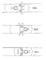
- wrap angle with which the tangential belts wrap around their pulleys is 360 °, as can be seen from FIG. 1. Depending on the arrangement of the deflection elements, this sum of angles can be distributed differently to the individual deflection elements, but always remains 360 °.
- tangential belt drive in which horizontal drive shafts run in the middle of the machine and are connected to angular drives (DE-B 1.141.571). These angular drives have superposed drive rollers over which tangential belts run. These in turn drive intermediate rollers, which each drive the corresponding drive elements of spindles via an individual, short, endless drive belt. This results in a large construction effort with considerable power loss.
- the present invention has for its object to increase the frictional connection between the tangential belt on the one hand and the deflection rollers and the drive pulleys on the other hand and thus to improve the energy transmission both from the motor to the tangential belt and between the tangential belt.
- This object is achieved in that it increases the sum of the deflection angle of a tangential belt beyond 360 °, that the increase in the sum of the deflection angle of a tangential belt by laying the drive rollers driving the tangential belt and / or by arranging further deflection roller elements and that the tangential belt corresponds to the Number of working units of each of the fields have a width between 7 and 15 mm and a thickness between 2 and 2.7 mm.
- a particularly advantageous measure of the invention consists in non-rotatably connecting the deflection rollers respectively assigned to the tangential belts in the additional deflection roller elements, so that these additional deflection rollers not only increase the wrapping bends on the drive pulleys and the already existing deflection roller elements, but also additionally their own wrapping bends for the energy transfer between the tangential belts take effect.
- the belt drive can be designed in a manner known per se as a flat or profile belt, for example a toothed belt, so that either non-positive or positive locking is possible.
- FIG. 1 illustrates how the sum of the wrap angles of 360 ° of a tangential belt 1 according to the prior art is distributed over four deflection rollers 2, 3, 4 and 5 and a drive roller 6. It can be seen that the wrap angles on the deflection rollers 2 and 3 are only 45 ° and on the drive roller 6 are only 90 °, a total of 180 °. The distribution of these 180 ° on these rollers can be changed by moving the drive roller 6, but when the wrap angle on the drive roller 6 is increased, the wrap angle on the deflection rollers 2 and 3 is reversed. A small wrap angle on the deflection rollers 2 and 3 affects the frictional connection between the tangential belt 1 and the deflection rollers and thus the possibility of energy transfer to an adjacent tangential belt 7. A small wrap angle on the drive roller 6 reduces the frictional connection between this roller and the tangential belt 1 and thus the transmission of the drive energy to the tangential belt.
- Fig. 2 illustrates how the wrap angle on the deflection rollers 2 and 3 and the drive roller can be increased significantly: the tangential belt 1 is deflected by laying the drive roller 6 in the opposite arc. Wrap angles on the deflection rollers 2 and 3 and the drive roller 6 of 165 ° and 150 ° are achieved.
- the two adjacent tangential belts 1 and 7 are driven by the drive pulley 6 of a motor 8.
- pinch roller pairs 10 ensure that the tangential belts 1 and 7 fit well against the whorls 11 of the work organs, not shown, spindles.
- the two tangential belts 1, 7 are guided vertically offset relative to one another via deflecting rollers 3 and 18, which are coupled to one another in a rotationally fixed manner and form deflecting roller elements 14 and 15.
- deflection roller elements 14 and 15 in addition to the deflection roller elements 14 and 15, further deflection roller elements 16 and 17 are provided against the longitudinal center of the machine.
- the tangential belt 1 runs around the deflection roller element 14, around the drive pulley 6 and around the deflection roller element 15.
- the tangential belt 7 runs around all four deflection roller elements 14, 16 and 17, 15, i.e. both deflection roller elements of each pair are wrapped in the tangential belt 7.
- the looping of the frictional connection and the energy transfer between the tangential belts 1 and 7 causing deflection roller elements 14 and 15 is doubled from 90 ° (FIG. 1) to approximately 180 ° and thus the possibility of transferring energy is significantly increased.
- Fig. 5 there is also the possibility, with a deflection roller arrangement as in Fig. 4, the motor 6 on the other side, i.e. to be arranged in the area of the tangential belt 7.
- the tangential belt 1 wraps around the two deflection roller elements 14 and 15 with its inside and the deflection roller elements 16 and 17 with its outside.
- the drive pulley 6 of the motor 8 is wrapped at an angle of around 180 °.
- the tangential belt 7 only wraps around the two deflection roller elements 16 and 17, each with approximately 90 °.
- the tangential belt 7 also wraps around the two deflection roller elements 16 and 17 with its outside.
- the two deflection roller elements 14 and 16 or 15 and 17 are wrapped by both tangential belts 1 and 7 with arches each of more than 90 °, with a particularly tight frictional connection and thus the possibility of transferring a lot of energy between the tangles tialriemen 1 and 7 is given. Dabie can be easily achieved by appropriate arrangement of the additional deflection roller elements 16 and 17 that the sum of the wrap angles of both tangential belts 1 and 7 is the same size around all four deflection roller elements.
- the deflection roller elements are arranged in such a way that the runs of the tangential belts 1, 7 running in the longitudinal direction of the machine are directed tangentially to the deflection rollers.
- the drive motor 8 with the drive pulley 6 sits in the middle of the machine and is offset from the plane connecting the axes of the two deflection roller elements by an amount which corresponds to at least half the distance between the runs of the tangential belts 1, 7 running on both machine sides.
- the deflection roller elements 16 and 17 are arranged between the two outer deflection roller elements 14 and 15 and the tangential belt 7 running between these deflection roller elements 14 and 15 with respect to the tangential connection plane between the deflection roller elements 14 and 15 by more than or at least deflect the diameter of the deflection rollers of these deflection roller elements.
- the deflection roller elements 16, 17 deflect the belt path leading from the deflection rollers of the deflection roller elements 14 and 15 to the drive pulley 6 by approximately the deflection pulley diameter such that the belt running directions leading to and from the drive pulley are approximately parallel to one another run.
- FIG. 6 shows a combination of the features of FIGS. 4 and 5.
- the tangential belt 1 here runs analogously to the running direction according to the tangential belt 1 in FIG. 5; the tangential belt 7 runs analogously to the running direction of the tangential belt 7 in FIG. 4.
- the respectively adjacent deflection roller elements 14 and 16 or 15 and 17 shown in FIGS. 4, 5 and 6 can in this case be mechanically coupled to one another.
- This coupling can take place, for example, by meshing gears, which supports any energy shift that may become necessary.
Landscapes
- Engineering & Computer Science (AREA)
- Mechanical Engineering (AREA)
- Textile Engineering (AREA)
- Spinning Or Twisting Of Yarns (AREA)
Abstract
Claims (10)
Applications Claiming Priority (4)
| Application Number | Priority Date | Filing Date | Title |
|---|---|---|---|
| DE3518998 | 1985-05-25 | ||
| DE19853518998 DE3518998A1 (de) | 1984-11-10 | 1985-05-25 | Maschine zum herstellen gedrehter oder gezwirnter faeden |
| DE19853519540 DE3519540A1 (de) | 1984-11-10 | 1985-05-31 | Maschine zum herstellen gedrehter oder gezwirnter faeden |
| DE3519540 | 1985-05-31 |
Publications (2)
| Publication Number | Publication Date |
|---|---|
| EP0223775A1 EP0223775A1 (fr) | 1987-06-03 |
| EP0223775B1 true EP0223775B1 (fr) | 1990-10-03 |
Family
ID=25832599
Family Applications (1)
| Application Number | Title | Priority Date | Filing Date |
|---|---|---|---|
| EP85905758A Expired - Lifetime EP0223775B1 (fr) | 1985-05-25 | 1985-10-16 | Transmission a courroie tangentielle |
Country Status (4)
| Country | Link |
|---|---|
| US (1) | US4781015A (fr) |
| EP (1) | EP0223775B1 (fr) |
| DE (1) | DE3580044D1 (fr) |
| WO (1) | WO1986007101A1 (fr) |
Families Citing this family (14)
| Publication number | Priority date | Publication date | Assignee | Title |
|---|---|---|---|---|
| DE3802200A1 (de) * | 1988-01-26 | 1989-08-03 | Zinser Textilmaschinen Gmbh | Maschine zum herstellen gedrehter oder gezwirnter faeden |
| DE3905534A1 (de) * | 1989-02-23 | 1990-08-30 | Stahlecker Fritz | Tangentialriemenantrieb fuer eine spinn- oder zwirnmaschine |
| US4944144A (en) * | 1989-05-17 | 1990-07-31 | Kabushiki Kaisha Ishikawa Seisakusho, Ltd. | Spindle driving device of covering machine |
| JPH0397924A (ja) * | 1989-09-05 | 1991-04-23 | Howa Mach Ltd | 精紡機のスピンドル駆動装置 |
| DE3934576A1 (de) * | 1989-10-17 | 1991-04-25 | Schubert & Salzer Maschinen | Streckwerk zum verziehen von faserbaendern |
| DE4004524A1 (de) * | 1990-02-14 | 1991-08-22 | Zinser Textilmaschinen Gmbh | Antrieb fuer eine spinnmaschine, insbesondere fuer einen fleyer |
| IT1243016B (it) * | 1990-09-19 | 1994-05-23 | Marzoli & C Spa | Dispositivo di azionamento dei fusi in un filatoio ad anelli o simile |
| US5222350A (en) * | 1990-12-06 | 1993-06-29 | Platt Saco Lowell Corporation | Roving frame and method |
| US20030022745A1 (en) * | 2001-07-26 | 2003-01-30 | Richard Kuchta | Multi-spindle drive and belt tensioning assembly |
| JP4939190B2 (ja) * | 2006-11-30 | 2012-05-23 | 本田技研工業株式会社 | 小型車両用パワーユニット |
| WO2009040839A1 (fr) * | 2007-09-28 | 2009-04-02 | Marzoli S.P.A. | Métier à filer avec système d'entraînement à courroie pour déplacer des broches |
| CN102367611A (zh) * | 2011-11-21 | 2012-03-07 | 杭州长翼纺织机械有限公司 | 复合捻线机上锭子龙带单元传动机构 |
| DE102011119416A1 (de) * | 2011-11-24 | 2013-05-29 | Agtatec Ag | Antriebsvorrichtung für einen Karusselltürrotor |
| EP3604643A1 (fr) * | 2018-08-01 | 2020-02-05 | Saurer Czech s.r.o. | Courroie d'entraînement et unité de transmission pour deux courroies d'entraînement disposées séquentiellement |
Family Cites Families (10)
| Publication number | Priority date | Publication date | Assignee | Title |
|---|---|---|---|---|
| DE1141571B (de) * | 1960-01-21 | 1962-12-20 | Skf Kugellagerfabriken Gmbh | Antrieb fuer Spindeln von Spinn- und Zwirnmaschinen |
| DE1244631B (de) * | 1960-11-22 | 1967-07-13 | Saco Lowell Shops | Spindelantriebsaggregat fuer Spinn- oder Zwirnmaschinen |
| GB1236254A (en) * | 1968-08-16 | 1971-06-23 | Scriven & Paget Ltd | Mechanism for rotating twist spindles |
| FR2124262A1 (en) * | 1971-02-01 | 1972-09-22 | Heberlein Hispano Sa | Spindle bank synchronisation - by non-slip belting between tension rollers of each bank |
| US3952495A (en) * | 1974-02-20 | 1976-04-27 | Roberts Company | Tension pulley assembly for textile spinning machines |
| US3974633A (en) * | 1975-10-06 | 1976-08-17 | Platt Saco Lowell Corporation | Noise isolation mounting means for tape tensioner assembly of a textile yarn twister |
| DE2610785A1 (de) * | 1976-03-15 | 1977-09-29 | Uniroyal Luxembourg | Ringzwirnmaschine |
| US4090348A (en) * | 1976-07-19 | 1978-05-23 | Spintex, Inc. | Spinning or twisting machine ring drive |
| DE2931716A1 (de) * | 1979-08-04 | 1981-02-19 | Barmag Barmer Maschf | Doppeldrahtzwirnmaschine |
| DE3500171A1 (de) * | 1985-01-04 | 1986-07-10 | Zinser Textilmaschinen Gmbh, 7333 Ebersbach | Maschine zur herstellung gedrehter oder gezwirnter faeden |
-
1985
- 1985-10-16 WO PCT/DE1985/000401 patent/WO1986007101A1/fr not_active Ceased
- 1985-10-16 US US07/027,030 patent/US4781015A/en not_active Expired - Fee Related
- 1985-10-16 DE DE8585905758T patent/DE3580044D1/de not_active Expired - Lifetime
- 1985-10-16 EP EP85905758A patent/EP0223775B1/fr not_active Expired - Lifetime
Also Published As
| Publication number | Publication date |
|---|---|
| EP0223775A1 (fr) | 1987-06-03 |
| US4781015A (en) | 1988-11-01 |
| DE3580044D1 (de) | 1990-11-08 |
| WO1986007101A1 (fr) | 1986-12-04 |
Similar Documents
| Publication | Publication Date | Title |
|---|---|---|
| EP0223775B1 (fr) | Transmission a courroie tangentielle | |
| DE2911379C2 (fr) | ||
| DE2641434B2 (de) | Lange Spinnmaschine | |
| CH668435A5 (de) | Maschine zum herstellen gedrehter faeden. | |
| DE4140984C2 (de) | Streckwerk für eine Spinnereimaschine, insbesondere Regulierstrecke für Baumwolle | |
| EP3662100B1 (fr) | Ros et métier à tisser circulaire | |
| DE2610785A1 (de) | Ringzwirnmaschine | |
| EP3133192B1 (fr) | Metier a tisser comprenant plusieurs bancs d'etirage adjacents | |
| DE2835973B2 (de) | Getriebe | |
| EP0202253B1 (fr) | Commande a courroie tangentielle pour metier a filer ou a retordre | |
| DE3209363C2 (de) | Doppeldrahtzwirnmaschine | |
| DE102013108095A1 (de) | Spinnmaschine und Falschdralleinrichtung | |
| EP0326003A2 (fr) | Machine pour la fabrication de fils tordus ou retordus | |
| EP3592530B1 (fr) | Système d'étirage de film | |
| DE69008209T2 (de) | Changierfadenführer. | |
| DE19649769A1 (de) | Lange Spinnmaschine | |
| WO2019015866A1 (fr) | Métier circulaire | |
| DE3519540A1 (de) | Maschine zum herstellen gedrehter oder gezwirnter faeden | |
| DE9207588U1 (de) | Steuermechanismus für die Platinen einer Fachbildungseinrichtung eines Webstuhls | |
| DE3207384A1 (de) | Vorrichtung zur folienreckung | |
| DE3622215A1 (de) | Antriebsvorrichtung fuer eine vielzahl von mit vorlagespulen bestueckten ablaufspindeln an einer zwirnmaschine | |
| DE102005054826B4 (de) | Ringspinnmaschine mit Streckwerken | |
| DE69031235T2 (de) | Vorrichtung zum Übertragen einer Drehbewegung zu einer Spindelgruppe einer Ringspinnmaschine | |
| EP1681259A2 (fr) | Dispositif d'entraînement unidirectionel pour des dispositifs de va-et-vient de fil | |
| DE102023000737A1 (de) | Changiereinrichtung und Aufspulvorrichtung zum Aufspulen mehrerer synthetischer Fäden mit einer Changiereinrichtung |
Legal Events
| Date | Code | Title | Description |
|---|---|---|---|
| PUAI | Public reference made under article 153(3) epc to a published international application that has entered the european phase |
Free format text: ORIGINAL CODE: 0009012 |
|
| 17P | Request for examination filed |
Effective date: 19870220 |
|
| AK | Designated contracting states |
Kind code of ref document: A1 Designated state(s): CH DE FR IT LI |
|
| 17Q | First examination report despatched |
Effective date: 19880707 |
|
| GRAA | (expected) grant |
Free format text: ORIGINAL CODE: 0009210 |
|
| AK | Designated contracting states |
Kind code of ref document: B1 Designated state(s): CH DE FR IT LI |
|
| ITF | It: translation for a ep patent filed | ||
| PGFP | Annual fee paid to national office [announced via postgrant information from national office to epo] |
Ref country code: FR Payment date: 19901009 Year of fee payment: 6 |
|
| ITTA | It: last paid annual fee | ||
| REF | Corresponds to: |
Ref document number: 3580044 Country of ref document: DE Date of ref document: 19901108 |
|
| PGFP | Annual fee paid to national office [announced via postgrant information from national office to epo] |
Ref country code: DE Payment date: 19901206 Year of fee payment: 6 |
|
| ET | Fr: translation filed | ||
| PGFP | Annual fee paid to national office [announced via postgrant information from national office to epo] |
Ref country code: CH Payment date: 19910115 Year of fee payment: 6 |
|
| PLBE | No opposition filed within time limit |
Free format text: ORIGINAL CODE: 0009261 |
|
| STAA | Information on the status of an ep patent application or granted ep patent |
Free format text: STATUS: NO OPPOSITION FILED WITHIN TIME LIMIT |
|
| 26N | No opposition filed | ||
| PG25 | Lapsed in a contracting state [announced via postgrant information from national office to epo] |
Ref country code: LI Effective date: 19911031 Ref country code: CH Effective date: 19911031 |
|
| PG25 | Lapsed in a contracting state [announced via postgrant information from national office to epo] |
Ref country code: FR Effective date: 19920630 |
|
| REG | Reference to a national code |
Ref country code: CH Ref legal event code: PL |
|
| PG25 | Lapsed in a contracting state [announced via postgrant information from national office to epo] |
Ref country code: DE Effective date: 19920701 |
|
| REG | Reference to a national code |
Ref country code: FR Ref legal event code: ST |