EP0223907B1 - Appareil pour mélanger des fluides multiples - Google Patents
Appareil pour mélanger des fluides multiples Download PDFInfo
- Publication number
- EP0223907B1 EP0223907B1 EP86107352A EP86107352A EP0223907B1 EP 0223907 B1 EP0223907 B1 EP 0223907B1 EP 86107352 A EP86107352 A EP 86107352A EP 86107352 A EP86107352 A EP 86107352A EP 0223907 B1 EP0223907 B1 EP 0223907B1
- Authority
- EP
- European Patent Office
- Prior art keywords
- mixing
- rotary member
- gap
- mixing head
- raw materials
- Prior art date
- Legal status (The legal status is an assumption and is not a legal conclusion. Google has not performed a legal analysis and makes no representation as to the accuracy of the status listed.)
- Expired
Links
- 239000012530 fluid Substances 0.000 title claims description 27
- 239000007788 liquid Substances 0.000 claims description 39
- 239000002994 raw material Substances 0.000 claims description 36
- 239000000203 mixture Substances 0.000 claims description 15
- 239000003599 detergent Substances 0.000 claims description 13
- 238000007789 sealing Methods 0.000 claims description 4
- 238000004140 cleaning Methods 0.000 description 23
- 238000001746 injection moulding Methods 0.000 description 12
- 238000000034 method Methods 0.000 description 10
- 239000000463 material Substances 0.000 description 7
- 239000004809 Teflon Substances 0.000 description 3
- 229920006362 Teflon® Polymers 0.000 description 3
- 238000013019 agitation Methods 0.000 description 3
- 238000010586 diagram Methods 0.000 description 3
- 238000002347 injection Methods 0.000 description 3
- 239000007924 injection Substances 0.000 description 3
- 238000012856 packing Methods 0.000 description 3
- 239000004677 Nylon Substances 0.000 description 2
- 229920001971 elastomer Polymers 0.000 description 2
- 238000010438 heat treatment Methods 0.000 description 2
- 239000002184 metal Substances 0.000 description 2
- 229920001778 nylon Polymers 0.000 description 2
- 239000000843 powder Substances 0.000 description 2
- 239000011369 resultant mixture Substances 0.000 description 2
- 230000000717 retained effect Effects 0.000 description 2
- 229920002379 silicone rubber Polymers 0.000 description 2
- JOYRKODLDBILNP-UHFFFAOYSA-N Ethyl urethane Chemical compound CCOC(N)=O JOYRKODLDBILNP-UHFFFAOYSA-N 0.000 description 1
- 230000002411 adverse Effects 0.000 description 1
- 230000000295 complement effect Effects 0.000 description 1
- 230000003247 decreasing effect Effects 0.000 description 1
- 239000000945 filler Substances 0.000 description 1
- 238000004519 manufacturing process Methods 0.000 description 1
- 230000013011 mating Effects 0.000 description 1
- 239000003960 organic solvent Substances 0.000 description 1
- 230000002093 peripheral effect Effects 0.000 description 1
- 229920003002 synthetic resin Polymers 0.000 description 1
- 239000000057 synthetic resin Substances 0.000 description 1
- 229910052724 xenon Inorganic materials 0.000 description 1
Images


Classifications
-
- B—PERFORMING OPERATIONS; TRANSPORTING
- B01—PHYSICAL OR CHEMICAL PROCESSES OR APPARATUS IN GENERAL
- B01F—MIXING, e.g. DISSOLVING, EMULSIFYING OR DISPERSING
- B01F31/00—Mixers with shaking, oscillating, or vibrating mechanisms
- B01F31/80—Mixing by means of high-frequency vibrations above one kHz, e.g. ultrasonic vibrations
- B01F31/82—Mixing by means of high-frequency vibrations above one kHz, e.g. ultrasonic vibrations the material being forced through a narrow vibrating slit
-
- B—PERFORMING OPERATIONS; TRANSPORTING
- B01—PHYSICAL OR CHEMICAL PROCESSES OR APPARATUS IN GENERAL
- B01F—MIXING, e.g. DISSOLVING, EMULSIFYING OR DISPERSING
- B01F27/00—Mixers with rotary stirring devices in fixed receptacles; Kneaders
- B01F27/27—Mixers with stator-rotor systems, e.g. with intermeshing teeth or cylinders or having orifices
- B01F27/272—Mixers with stator-rotor systems, e.g. with intermeshing teeth or cylinders or having orifices with means for moving the materials to be mixed axially between the surfaces of the rotor and the stator, e.g. the stator rotor system formed by conical or cylindrical surfaces
- B01F27/2722—Mixers with stator-rotor systems, e.g. with intermeshing teeth or cylinders or having orifices with means for moving the materials to be mixed axially between the surfaces of the rotor and the stator, e.g. the stator rotor system formed by conical or cylindrical surfaces provided with ribs, ridges or grooves on one surface
-
- B—PERFORMING OPERATIONS; TRANSPORTING
- B01—PHYSICAL OR CHEMICAL PROCESSES OR APPARATUS IN GENERAL
- B01F—MIXING, e.g. DISSOLVING, EMULSIFYING OR DISPERSING
- B01F27/00—Mixers with rotary stirring devices in fixed receptacles; Kneaders
- B01F27/27—Mixers with stator-rotor systems, e.g. with intermeshing teeth or cylinders or having orifices
- B01F27/272—Mixers with stator-rotor systems, e.g. with intermeshing teeth or cylinders or having orifices with means for moving the materials to be mixed axially between the surfaces of the rotor and the stator, e.g. the stator rotor system formed by conical or cylindrical surfaces
- B01F27/2723—Mixers with stator-rotor systems, e.g. with intermeshing teeth or cylinders or having orifices with means for moving the materials to be mixed axially between the surfaces of the rotor and the stator, e.g. the stator rotor system formed by conical or cylindrical surfaces the surfaces having a conical shape
Definitions
- the present invention relates to an apparatus for mixing a plurality of fluids, e.g. for mixing liquified raw materials to be utilized in a reactive injection molding machine, a vacuum injection molding machine, small-scale dispenser, etc.
- various methods have been used to mix such liquified raw materials.
- the liquids to be mixed are led into a vessel, and mixed therein by a forcible mixing apparatus having mixing vanes, which may be of various shapes.
- the liquids to be mixed are caused to flow between fixed separator plates and separator vanes, to ensure that the liquids remain separated until mixing is initiated.
- the raw materials are made to mutually collide under high pressure, within a narrow chamber, to thereby accomplish mixing.
- mixing is performed by an apparatus according to the present invention within a gap which is opened between two opposing surfaces, with one of these surfaces being rotated with respect to the other surface to thereby produce shear stress between liquids which are injected into the gap, and to thereby effectively mix the liquids.
- the mixture is ejected from an aperture formed in one of these surfaces close to the center of rotation.
- the mixing gap is closed, by bringing the two surfaces into close contact, whereby the residual mixture is substantially completely ejected from the ejection aperture.
- Cleaning of the mixing surfaces can then be performed by again opening a gap between them, and passing flows of cleaning fluids, such as detergent liquid and a cleaning gas, between the surfaces while one surface is rotated with respect to the other.
- the present invention comprises an apparatus for mixing a plurality of liquids as defined in claim 1.
- FIG. 1 denotes a mixing head having an ejection aperture 2 formed in a lower face 1a, for outlet of a mixture of raw material fluids upon completion of mixing.
- the lower face 1a of mixing head 1 is of concave conical shape, while a cylindrical surface 1b of a tubular bore formed in the mixing head 1 extends upward from the outer periphery of the lower surface 1a, i.e. with the lower surface 1a extending radially inward from a lower end of that tubular bore.
- Numeral 3 denotes a rotary member which fits closely within the cylindrical surface 1b and has a lower face formed thereon which is of convex conical shape, formed such as to be capable of mating closely against the lower face 1b of the mixing head 1.
- the rotary member 3 is supported by a shaft 4 such as to permit rotation of rotary member 3 about the central axis of shaft 4, in the direction indicated by arrow Y, and further such as to permit movement of the rotary member 3 along the direction of the central axis of shaft 4 for enabling a first condition to be established in which the rotary member 3 is separated from the conical lower face 1a of mixing head 1 by a specific gap ⁇ d (referred to in the following as the mixing gap), and a second condition in which the rotary member 3 is brought into close contact with the lower face 1a by movement along the direction indicated by arrow X.
- a specific gap ⁇ d referred to in the following as the mixing gap
- the mixing gap ⁇ d is formed between the opposed conical surfaces of the mixing head 1 and rotary member 3 and a small peripheral section of the cylindrical surface 1b.
- Numerals 5 and 6 denote two of a plurality of supply apertures which are formed mutually independently and serve to supply liquids to the mixing gap ⁇ d.
- Numeral 7 denotes a set of fluid-tight sealing rings which are disposed between the periphery of the rotary member 3 and the cylindrical surface 3a of the mixing head 1.
- Numerals 8 and 9 denote fluid inlet apertures for respectively receiving the fluids to be mixed, designated as A and B. These fluids then pass through passages 8a, 9a to supply apertures 5 and 6 respectively.
- the mixing head 1 further includes a detergent liquid inlet aperture 10 which communicates with a supply aperture 10a, leading into the mixing gap d, and a cleaning gas inlet aperture 11 which communicates with a supply aperture (not shown in the drawings) leading into mixing gap ⁇ d.
- Numeral 12 denotes an elastic body which serves to move the rotary member 3 along the direction of arrow X when the supply of fluids under pressure to the mixing gap ⁇ d is halted, as described hereinafter.
- FIGs. 3(a) to (c) are partial cross-sectional views for assistance in describing the operation.
- the fluids A and B constituting the raw materials are ejected out of the supply apertures 5 and 6 under sufficient pressure to overcome a force exerted by the elastic body 12, i.e. a force acting to push the conical surfaces of the mixing head 1 and the rotary member 3 into close contact.
- a mixing gap ⁇ d is thereby formed between the lower surface 1a and an opposing surface 3a of the rotary member 3, into which the raw materials are forced.
- the rotary member 3 is then rotated at high speed by shaft 4 (i.e. in the direction of arrow Y in Fig.
- a detergent liquid and a detergent gas are successively injected, under sufficient pressure to overcome the biasing force exerted by the elastic body 12, through the fluid inlet apertures 10 and 11.
- the rotary member 3 is thereby forced upward, to open a gap ⁇ d ⁇ , which is smaller than the mixing gap ⁇ d, as illustrated in Fig. 3(c).
- the rotary member 3 is the rotated at high speed in the direction of arrow Y, whereby all residual mixture is effectively cleaned from the conical faces 1a and 3a.
- the injection of detergent liquid and cleaning gas is halted when cleaning is completed, whereupon the biasing force produced by the elastic body 12 closes the gap ⁇ d ⁇ . This completes a cycle of operations in which mixing is performed, followed by cleaning of the mixing head.
- a plurality of fluids constituting raw materials are respectively injected under between two mixing surfaces (1a and 3a) being held in close contact by a biasing force produced by an elastic body, whereby a mixing gap is opened between the two surfaces. Relative motion at high speed is then produced between these two surfaces, resulting in shear stress being produced in the raw materials within the mixing gap, and hence effective mixing of the raw materials.
- the two mixing surfaces are brought into close contact by the biasing force of the elastic body, to thereby eject a maximum amount of residual mixture remaining between the two surfaces.
- the mixing surfaces are then forced slightly apart by injection of a detergent liquid and a cleaning gas between them under pressure, and relative motion is again produced between the surfaces, to implement effective cleaning of the surfaces.
- the two mixing surfaces be of mutually complementary conical shapes, i.e. respectively convex and concave, to thereby enable the surfaces to be readily brought into close contact, and thereby enable optimum removal of any residual mixture left between the mixing surfaces upon completion of mixing operation.
- the size of the gap between the mixing surfaces during cleaning, when detergent liquid and cleaning gas are being injected under pressure between the two surfaces be made smaller than the size of gap during mixing. This narrower gap during cleaning serves to increase the resistance to flow of the detergent liquid and cleaning gas through the gap, and hence increases the effectiveness of cleaning the mixing surfaces.
- a detergent liquid such as an organic solvent is injected between the mixing surfaces, to produce a gap between the surfaces and to flow into this gap.
- a cleaning gas consisting of an inactive gas such as N2 is injected under pressure to flow betwen the surfaces.
- the cone plate unit 23 is further movable along the direction indicated by arrow X/Z, to form a gap ⁇ d, by the action of an actuating cylinder (described hereinafter).
- the raw materials to be mixed consist of nylon of a type which is suitable for reactive injection molding (RIM) (for example UX-B material manufactured by the Ube Kosan Co. Ltd) and urethane (e.g. manufactured by Nippon Xenon Co. Ltd).
- RIM reactive injection molding
- the two fluids constituting the raw materials designated respectively as A and B, are caused to flow along paths 30 and 31 shown in Fig. 4(b) respectively, through respective passages formed in the mixing head (one of which is indicated as 28 in Fig.
- a piston 32b having mixing vanes formed thereon, is rotated by a piston drive screw 37, and also is moved axially by rotation of piston drive screw 37 as indicated by the arrows.
- the piston 32b is sealed within the bore of cylinder 32 by means of a teflon member 39 and by silicon rubber packing rings 38.
- An agitation vane rotation shaft 40 passes through the central axial portion of the piston drive screw 37, and is retained at one end thereof to one end of cylinder 32 by means of a retaining ring 43.
- the agitation vane rotation shaft 40 serves to rotate a set of agitation vanes 42 at high speed, and is sealed by means of sealing rings 41.
- the reactive raw material is supplied from a raw material tank, through a valve which is coupled to an inlet aperture 44.
- a valve which is coupled to an inlet aperture 44.
- the piston 32b When the piston 32b is retracted, i.e. moved to the left (as seen in Fig. 5), the raw material is drawn into the interior of the cylinder 32, and when the piston is then advanced (i.e. moved to the right, as seen in Fig. 5), the raw material is injected through a supply passage 30 into the mixing gap.
- piston screw 37 are rotatated by a motor 52, acting through a chain 49 and gearwheels 50 and 51 which provide a specific degree of speed reduction and thereby determine the speed of advancement and retraction of the pistons.
- the piston cylinders 32 and 20 and the mixing head block 45 are contained within a chamber 57. Heating to maintain the temperature within chamber 57 to a specific level is implemented by a flow of hot air 60 which flows in the direction indicated by the arrows, and is produced by a heater 59 and an impeller fan 58, driven through gear wheels 55, 56 by a motor 54.
- Numeral 63 denotes a reactive forming mold, composed of a material such as metal or rubber, which can be removably attached to the nozzle 24 constituting the ejection aperture of the mixing apparatus.
- the mixing apparatus also includes a drive motor 61, for rotating the rotary member 23, and an actuating piston 62 moving within a cylinder and coupled to rotary member 23.
- the actuating piston 62 operates to move the rotary member 23 upward or downward, to open or close the mixing gap ⁇ d respectively, by introduction of a gas or fluid under pressure into a lower and an upper chamber respectively of the cylinder in which piston 62 moves.
- Fig. 7(a) and 7(b) are external views in plan and elevation respectively of a bench-mounting reactive injection molding which incorporates the mixing apparatus of Fig. 6.
- Numeral 65 denotes a cover which is mounted over the gear wheels driving the heating air impeller fan, while numeral 64 denotes a cover mounted over the piston screw drive assembly.
- the reactive injection molding unit is retained by an attachment member 68, and is moved upward or downward by rotation of a handle 66 which is rotatably mounted at the upper end of a supporting pillar 67a which is mounted on a base 67b.
- FIGs. 8(a) and 8(b) are cross-sectional views in elevation and plan respectively of a mixing head of this embodiment, with Fig. 8(b) being taken along line p-p ⁇ shown in Fig. 8(a).
- a rotary member 74 is formed with a convex conical lower face 74a.
- An attachment member 72 is formed with a concave conical surface 72a, and is mounted at the lower end of a supporting member 71 in the form of a cylinder, constituting the body of the mixing head.
- the attachment member 72 is attached to the supporting member 71 by means of bolts 73, with a separator plate 85 being clamped between members 72 and 71.
- the rotary member 74 slidably fits within a central bore of cylinder 71.
- the rotary member 74 is movable axially upward and downward, to respectively open and close a mixing gap ⁇ d formed between the surfaces 72a and 74a, and is rotated during mixing in the direction indicated by arrow 88, at a speed which is determined in accordance with the viscosity of the fluids to be mixed and the rate of flow of the fluids into gap ⁇ d, together with the size of gap ⁇ d.
- a plurality of sealing rings 77 are mounted on the periphery of an upper part of rotary member 74.
- the rotary member 74 is coupled by a shaft 86 to a drive motor and actuating piston (not shown in the drawings), as for the second embodiment of the invention described hereinabove, whereby rotation of the rotary member and selective opening and closing of the mixing gap ⁇ d are performed.
- This embodiment is assumed to be applied to mixing of two fluid raw materials, designated as A and B.
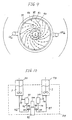
- Fig. 9 is a plan outline view, for illustrating the manner in which mixing of the two liquids takes place, as a result of the successively alternating arrangement of the supply apertures 81, 82.
- the mixing gap ⁇ d is of relatively large size and that the rotary member 104 is rotating relatively slowly.
- Fig. 10 is a block diagram to illustrate the general configuration of a nylon reactive injection molding, employing the third embodiment of a mixing apparatus according to the present invention. It is assumed that the raw materials are initially in the form of powders. The raw material powders are respectively placed in two raw material tanks 92 and 92, and are melted therein by being heated to a temperature of 80 to 90°C. The liquified raw material A is then passed from tank 92 along a path leading through a pipe 97, a gear pump 98, a pipe 96, a 3-way valve 95, and a pipe 94, back into tank 92.
- the liquified raw material B is passed from tank 93 along a path leading through a pipe 102, a gear pump 103, a pipe 101, a 3-way valve 100, and a pipe 99, back into tank 93.
- the 3-way valves 95 and 100 are actuated such as to transfer the liquified raw materials A and B through pipes 104 and 105 respectively to the mixing head 91, and mixed therein.
- a head drive unit 106 positioned above the mixing head 91 contains a drive motor and an actuating piston forming a single unit. All of the above components other than the inlet apertures of tanks 92 and 93 and the ejection aperture of the mixing head 91 are contained within a constant-temperature oven 107, to be held thereby at a temperature of 80°C or higher.
- the ejection aperture of mixing head 91 leads into a rubber or metal mold, whereby molded components of various type may be produced.
- each of the raw materials is transferred into the mixing gap through two or more supply apertures, and that the supply apertures are arranged in mutually successively alternating positions around the periphery of the mixing gap. This ensures more effective mixing of the raw materials by shear stress produced within the mixing gap than is possible with a more simple arrangement in which such a system of alternately arranged supply apertures is not employed. This embodiment of the present invention therefore ensures effective mixing of raw materials which have a high degree of viscosity.
Landscapes
- Chemical & Material Sciences (AREA)
- Chemical Kinetics & Catalysis (AREA)
- Processing And Handling Of Plastics And Other Materials For Molding In General (AREA)
- Injection Moulding Of Plastics Or The Like (AREA)
Claims (7)
- Appareil pour mélanger une pluralité de liquides, comportant :
une tête de mélange (1) ayant un perçage cylindrique formé à l'intérieur de celle-ci, et ayant une surface inférieure avec une ouverture d'éjection (2) formée à l'intérieur de celle-ci pour l'éjection d'un mélange desdits liquides après le mélange,
un élément rotatif (3) ayant une forme lui permettant de s'adapter étroitement à l'intérieur dudit perçage cylindrique à l'opposé de ladite surface inférieure de ladite tête de mélange, et supporté par un arbre (4) pour effectuer une rotation par rapport à ladite surface inférieure de ladite tête de mélange et pour se déplacer le long de l'axe de ladite rotation,
des moyens pour faire tourner ledit élément rotatif (3),
une pluralité d'ouvertures (5, 6) formées dans ladite tête de mélange (1) pour délivrer des matériaux bruts sous forme liquide,
des moyens pour délivrer lesdits matériaux bruts liquides auxdites ouvertures de délivrance (5, 6), caractérisé par :
un corps élastique (12) exerçant une force sur ledit élément rotatif (3) pour établir sélectivement une condition dans laquelle ledit élément rotatif (3) est en contact étroit avec ladite surface inférieure de ladite tête de mélange (1) et une condition dans laquelle un espace de mélange (Δd) est formé entre ledit élément rotatif (3), ladite surface inférieure de la tête de mélange (1) et une section circonférencielle dudit perçage cylindrique (1b), et
des moyens de scellement (7) disposés entre ledit élément rotatif (3) et ladite tête de mélange (1). - Appareil de mélange selon la revendication 1, dans lequel ladite surface inférieure (1a) de la tête de mélange et une surface inférieure dudit élément rotatif (3) disposée à l'opposé de celle-ci ont respectivement une surface conique concave et une surface conique convexe, afin de permettre un contact étroit entre lesdites surfaces en d'autres endroits que les parties de celles-ci correspondant à ladite ouverture d'éjection.
- Appareil de mélange selon la revendication 1, dans lequel une pluralité d'ouvertures indépendantes desdites ouvertures de délivrance (5, 6) sont présentes pour délivrer chacun desdits matériaux bruts liquéfiés audit espace de mélange (Δd).
- Appareil de mélange selon la revendication 3, dans lequel les ouvertures successives d'une pluralité d'ouvertures de délivrance pour l'un desdits matériaux bruts et les ouvertures successives d'une pluralité d'ouvertures de délivrance pour au moins un autre matériau brut sont disposées de façon circonférencielle dans des positions mutuellement alternées le long de la direction de rotation dudit élément rotatif.
- Appareil de mélange selon la revendication 1, comportant de plus une pluralité de rainures annulaires superposées verticalement disposées de façon périphérique à l'extérieur dudit espace de mélange et de passages de délivrance pour délivrer lesdits liquides à des rainures respectives parmi lesdites rainures annulaires, et une pluralité de rainures s'étendant radialement, s'étendant depuis l'une desdites rainures annulaires jusqu'audit espace de mélange afin de former par conséquent lesdites ouvertures de délivrance.
- Appareil de mélange selon l'une quelconque des revendications précédentes, dans lequel au moins une ouverture (10) est présente pour délivrer un fluide détergent audit espace de mélange (Δd).
- Appareil de mélange selon la revendication 6, dans lequel ladite surface inférieure de ladite tête de mélange et une surface dudit élément rotatif disposée à l'opposé de celle-ci ont respectivement une forme conique concave et une forme conique convexe, une ouverture d'éjection (2) étant formée au centre de ladite surface conique concave (1a).
Applications Claiming Priority (4)
| Application Number | Priority Date | Filing Date | Title |
|---|---|---|---|
| JP60267879A JPS62129133A (ja) | 1985-11-28 | 1985-11-28 | 混合ヘツド |
| JP267879/85 | 1985-11-28 | ||
| JP271846/85 | 1985-12-03 | ||
| JP60271846A JPS62132526A (ja) | 1985-12-03 | 1985-12-03 | 混合ヘツド |
Publications (3)
| Publication Number | Publication Date |
|---|---|
| EP0223907A2 EP0223907A2 (fr) | 1987-06-03 |
| EP0223907A3 EP0223907A3 (en) | 1988-08-10 |
| EP0223907B1 true EP0223907B1 (fr) | 1991-08-07 |
Family
ID=26548075
Family Applications (1)
| Application Number | Title | Priority Date | Filing Date |
|---|---|---|---|
| EP86107352A Expired EP0223907B1 (fr) | 1985-11-28 | 1986-05-30 | Appareil pour mélanger des fluides multiples |
Country Status (3)
| Country | Link |
|---|---|
| US (1) | US4834545A (fr) |
| EP (1) | EP0223907B1 (fr) |
| DE (1) | DE3680756D1 (fr) |
Families Citing this family (49)
| Publication number | Priority date | Publication date | Assignee | Title |
|---|---|---|---|---|
| DE69022714T2 (de) * | 1990-02-22 | 1996-05-09 | Minnesota Mining & Mfg | Statische Mischvorrichtung. |
| EP0452530A1 (fr) * | 1990-04-20 | 1991-10-23 | BRAN + LUEBBE GmbH | Dispositif de mélange |
| US5358329A (en) * | 1993-02-12 | 1994-10-25 | Fluid Dynamics, Inc. | Apparatus for mixing plural flowable materials |
| US5403092A (en) * | 1994-02-01 | 1995-04-04 | Eastman Kodak Company | Viscous shear mixing device and method |
| DE59503328D1 (de) * | 1994-05-31 | 1998-10-01 | Mark Braendli | Mischkopf zum mischen von fluiden, insbesondere gasen und/oder flüssigkeiten |
| US5938079A (en) * | 1995-01-27 | 1999-08-17 | Nordson Corporation | Dispensing head for two-component foam with shutoff |
| US5891526A (en) * | 1995-12-01 | 1999-04-06 | International Business Machines Corporation | Apparatus for mixing a multi-component encapsulant and injecting it through a heated nozzle onto a part to be encapsulated |
| JPH1029213A (ja) * | 1996-07-15 | 1998-02-03 | Toray Dow Corning Silicone Co Ltd | 液状材料連続混合装置 |
| US6702949B2 (en) | 1997-10-24 | 2004-03-09 | Microdiffusion, Inc. | Diffuser/emulsifier for aquaculture applications |
| US7128278B2 (en) * | 1997-10-24 | 2006-10-31 | Microdiffusion, Inc. | System and method for irritating with aerated water |
| US6386751B1 (en) * | 1997-10-24 | 2002-05-14 | Diffusion Dynamics, Inc. | Diffuser/emulsifier |
| US7654728B2 (en) * | 1997-10-24 | 2010-02-02 | Revalesio Corporation | System and method for therapeutic application of dissolved oxygen |
| US6004024A (en) | 1997-11-14 | 1999-12-21 | Calgon Corporation | Emulsion feed assembly |
| WO2000003578A2 (fr) * | 1998-07-16 | 2000-01-27 | Renner Herrmann S.A. | Dispositif de melange de fluide et soupape d'injection de fluide s'utilisant avec celui-ci |
| US6105822A (en) * | 1999-09-08 | 2000-08-22 | Liquid Control Corporation | Device and method for mixing and dispensing two flowable materials |
| GB0008553D0 (en) | 2000-04-06 | 2000-05-24 | Unilever Plc | Process and apparatus for the production of a detergent bar |
| US6536936B1 (en) | 2000-09-15 | 2003-03-25 | Masco Corporation | Mix head assembly for a molding material delivery system |
| US20040079417A1 (en) * | 2001-04-23 | 2004-04-29 | Auad Rogerio Batista | Fluid mixing device and fluid injection valve for use therewith |
| WO2002092310A1 (fr) * | 2001-05-17 | 2002-11-21 | Tesa Ag | Transport de fluides tres visqueux dans des systemes de conduites fermes |
| DE10361411B4 (de) * | 2003-12-29 | 2007-12-20 | Albert-Ludwigs-Universität Freiburg, vertreten durch den Rektor | Mischervorrichtung und Verfahren zum Mischen von zumindest zwei Flüssigkeiten |
| US7223307B2 (en) * | 2004-01-21 | 2007-05-29 | 3M Innovative Properties Company | Disc coater |
| US7445372B1 (en) * | 2004-10-01 | 2008-11-04 | Access Business Group International Llc | Custom cosmetic mixer |
| DE102006009117A1 (de) * | 2006-02-24 | 2007-09-06 | Krauss-Maffei Kunststofftechnik Gmbh | Mischkopf mit Kriechsperre am Reinigungskolben |
| US8784898B2 (en) | 2006-10-25 | 2014-07-22 | Revalesio Corporation | Methods of wound care and treatment |
| JP5491185B2 (ja) | 2006-10-25 | 2014-05-14 | リバルシオ コーポレイション | 傷のケアおよび処置の方法 |
| US8597689B2 (en) | 2006-10-25 | 2013-12-03 | Revalesio Corporation | Methods of wound care and treatment |
| US8784897B2 (en) | 2006-10-25 | 2014-07-22 | Revalesio Corporation | Methods of therapeutic treatment of eyes |
| US8609148B2 (en) | 2006-10-25 | 2013-12-17 | Revalesio Corporation | Methods of therapeutic treatment of eyes |
| AU2007308838B2 (en) | 2006-10-25 | 2014-03-13 | Revalesio Corporation | Mixing device and output fluids of same |
| US8445546B2 (en) | 2006-10-25 | 2013-05-21 | Revalesio Corporation | Electrokinetically-altered fluids comprising charge-stabilized gas-containing nanostructures |
| US9745567B2 (en) | 2008-04-28 | 2017-08-29 | Revalesio Corporation | Compositions and methods for treating multiple sclerosis |
| US10125359B2 (en) | 2007-10-25 | 2018-11-13 | Revalesio Corporation | Compositions and methods for treating inflammation |
| US9523090B2 (en) | 2007-10-25 | 2016-12-20 | Revalesio Corporation | Compositions and methods for treating inflammation |
| US20090227018A1 (en) * | 2007-10-25 | 2009-09-10 | Revalesio Corporation | Compositions and methods for modulating cellular membrane-mediated intracellular signal transduction |
| US8980325B2 (en) | 2008-05-01 | 2015-03-17 | Revalesio Corporation | Compositions and methods for treating digestive disorders |
| US8122956B2 (en) * | 2008-07-03 | 2012-02-28 | Baker Hughes Incorporated | Magnetic stirrer |
| US8815292B2 (en) | 2009-04-27 | 2014-08-26 | Revalesio Corporation | Compositions and methods for treating insulin resistance and diabetes mellitus |
| BR112012028540A2 (pt) | 2010-05-07 | 2016-07-26 | Revalesio Corp | composições e métodos para melhorar desempenho fisiológico e tempo de recuperação |
| JP2013533320A (ja) | 2010-08-12 | 2013-08-22 | レバレジオ コーポレイション | タウオパチーを治療するための組成物および方法 |
| EP2644344B1 (fr) * | 2012-03-26 | 2014-08-13 | Siemens Aktiengesellschaft | Dispositif de mélange pour un processus fermé d'infusion de résine |
| JP6291903B2 (ja) * | 2014-02-26 | 2018-03-14 | 株式会社ジェイテクト | 混練装置 |
| CN105751399B (zh) * | 2014-12-15 | 2018-10-26 | 凯力实业股份有限公司 | 节能减碳复合式塑粒的制造机构 |
| CN112188933B (zh) * | 2018-06-21 | 2022-08-16 | 宝洁公司 | 用于共注入两种或更多种液体的一体式分配喷嘴及其使用方法 |
| CA3101820C (fr) | 2018-06-22 | 2023-10-24 | The Procter & Gamble Company | Systeme de remplissage de liquide et son procede d'utilisation |
| GB2585710B (en) | 2019-07-15 | 2023-09-06 | Agilent Technologies Inc | Mixing fluid by combined axial motion and rotation of mixing body |
| EP4076761A1 (fr) | 2019-12-16 | 2022-10-26 | The Procter & Gamble Company | Système de distribution de liquide comprenant une buse de distribution unitaire |
| CN115591433B (zh) * | 2022-12-13 | 2023-03-07 | 乐比(广州)健康产业有限公司 | 一种口腔清新喷雾制作成分混合装置 |
| CN116099403B (zh) * | 2023-04-10 | 2023-07-11 | 赛尔托马斯生物科技(成都)有限公司 | 一种抗原与佐剂的混匀器及混匀装置 |
| CN117123079B (zh) * | 2023-09-27 | 2024-03-19 | 中科华鲁土壤修复工程有限公司 | 土壤修复加药系统 |
Family Cites Families (15)
| Publication number | Priority date | Publication date | Assignee | Title |
|---|---|---|---|---|
| US2333456A (en) * | 1941-10-09 | 1943-11-02 | Cities Service Oil Co | Method and apparatus for preparing dispersions |
| DE1090183B (de) * | 1955-11-12 | 1960-10-06 | Draiswerke Ges Mit Beschraenkt | Mischer bzw. Kneter, vornehmlich zur Verarbeitung hochviskoser Massen |
| US3180350A (en) * | 1962-04-20 | 1965-04-27 | Gen Motors Corp | Mixing apparatus |
| DE1454868B1 (de) * | 1965-05-31 | 1970-04-16 | Siemens Ag | Mischeinrichtung zum kontinuierlichen Herstellen von Kunststoffmischungen |
| FR1449984A (fr) * | 1965-09-24 | 1966-05-06 | Fitchburg Paper | Dispositif à ultra-sons pour la mise en suspension de matières |
| FR1533768A (fr) * | 1967-08-08 | 1968-07-19 | Appareil pour le traitement de suspensions fluides à l'aide de corps broyeurs | |
| DE1936945A1 (de) * | 1969-07-21 | 1971-02-04 | List Dipl Ing Heinz | Maschine zum Verarbeiten von fliessfaehigen Suspensionen |
| US3632022A (en) * | 1969-10-06 | 1972-01-04 | Usm Corp | Molding machinery |
| US3997145A (en) * | 1972-06-05 | 1976-12-14 | New Process Industries, Inc. | Oscillating mixer and method |
| AU499635B2 (en) * | 1976-02-20 | 1979-04-26 | Thapa Chemical Industry Co Ltd | Material mixing apparatus |
| GB1582248A (en) * | 1976-09-07 | 1981-01-07 | Clark Ltd C & J | Moulding of plastics |
| DE2911547A1 (de) * | 1979-03-23 | 1980-09-25 | Bayer Ag | Verfahren und vorrichtung zum herstellen eines massive oder zellfoermige stoffe bildenden reaktionsgemisches aus fliessfaehigen reaktionskomponenten und gegebenenfalls fuellstoffen |
| GB2048093B (en) * | 1979-04-11 | 1982-11-24 | Ciba Geigy Ag | Apparatus for the production of curable resin foam |
| US4426023A (en) * | 1981-03-06 | 1984-01-17 | Sealed Air Corporation | Cleaning assembly for a foam dispensing apparatus |
| DE3210978A1 (de) * | 1982-03-25 | 1983-09-29 | Basf Ag, 6700 Ludwigshafen | Mischvorrichtung fuer mehrkomponentenkunststoffe, insbesondere polyurethan |
-
1986
- 1986-05-30 EP EP86107352A patent/EP0223907B1/fr not_active Expired
- 1986-05-30 DE DE8686107352T patent/DE3680756D1/de not_active Expired - Lifetime
- 1986-06-04 US US06/870,410 patent/US4834545A/en not_active Expired - Fee Related
Also Published As
| Publication number | Publication date |
|---|---|
| DE3680756D1 (de) | 1991-09-12 |
| US4834545A (en) | 1989-05-30 |
| EP0223907A3 (en) | 1988-08-10 |
| EP0223907A2 (fr) | 1987-06-03 |
Similar Documents
| Publication | Publication Date | Title |
|---|---|---|
| EP0223907B1 (fr) | Appareil pour mélanger des fluides multiples | |
| KR100771456B1 (ko) | 유체를 지향시키는 멀티포트 로터리 밸브 | |
| US5246660A (en) | Process and apparatus for injection molding with melt filtration and mixing | |
| US6105822A (en) | Device and method for mixing and dispensing two flowable materials | |
| CA1061975A (fr) | Moulage automatise | |
| US6343496B1 (en) | Can shaping apparatus and method | |
| EP0209888B1 (fr) | Méthode pour mélanger des produits de base pour une réaction et appareil à cet effet | |
| US6109909A (en) | Pre-plasticizing injection apparatus having a plurality of heating and injecting cylinders and injection molding method of using the same | |
| US4368984A (en) | Mixer apparatus | |
| JPS6341727B2 (fr) | ||
| US4119304A (en) | Apparatus for mixing and dispensing fast setting plastic material into a mold | |
| US3271820A (en) | Pelletizer with steam ejection of pellets | |
| CN2323876Y (zh) | 高速立式刮刀下部卸料沉降离心机 | |
| US2719326A (en) | Plastic molding machines | |
| US2476219A (en) | Rotary transfer molding device | |
| JPH10216418A (ja) | 濾過機 | |
| JP2003516850A6 (ja) | 粘性液の混合装置 | |
| CN210522962U (zh) | 点胶头 | |
| JP3903328B2 (ja) | ロータリ式洗びん機のロータリバルブ押圧装置およびロータリバルブ洗浄装置 | |
| WO2004009317A1 (fr) | Dispositif de formation de quantites predeterminees de matiere synthetique | |
| US5266261A (en) | Process and apparatus for the production of molded articles from hot-setting plastics of several components by low-pressure casting | |
| JPH09109184A (ja) | 化学反応性の複数のプラスチック成分から形成されたプラスチック混合物を搬送する装置 | |
| GB2126490A (en) | Mixing head and actuator mechanism suitable therefor | |
| CN119455784B (zh) | 一种纺织品染整用染料混合装置及方法 | |
| CN213160732U (zh) | 一种化工生产用反应釜 |
Legal Events
| Date | Code | Title | Description |
|---|---|---|---|
| PUAI | Public reference made under article 153(3) epc to a published international application that has entered the european phase |
Free format text: ORIGINAL CODE: 0009012 |
|
| AK | Designated contracting states |
Kind code of ref document: A2 Designated state(s): DE FR GB |
|
| PUAL | Search report despatched |
Free format text: ORIGINAL CODE: 0009013 |
|
| AK | Designated contracting states |
Kind code of ref document: A3 Designated state(s): DE FR GB |
|
| 17P | Request for examination filed |
Effective date: 19881216 |
|
| 17Q | First examination report despatched |
Effective date: 19891020 |
|
| GRAA | (expected) grant |
Free format text: ORIGINAL CODE: 0009210 |
|
| AK | Designated contracting states |
Kind code of ref document: B1 Designated state(s): DE FR GB |
|
| REF | Corresponds to: |
Ref document number: 3680756 Country of ref document: DE Date of ref document: 19910912 |
|
| ET | Fr: translation filed | ||
| PLBE | No opposition filed within time limit |
Free format text: ORIGINAL CODE: 0009261 |
|
| STAA | Information on the status of an ep patent application or granted ep patent |
Free format text: STATUS: NO OPPOSITION FILED WITHIN TIME LIMIT |
|
| 26N | No opposition filed | ||
| PGFP | Annual fee paid to national office [announced via postgrant information from national office to epo] |
Ref country code: FR Payment date: 19950510 Year of fee payment: 10 |
|
| PGFP | Annual fee paid to national office [announced via postgrant information from national office to epo] |
Ref country code: GB Payment date: 19950519 Year of fee payment: 10 |
|
| PGFP | Annual fee paid to national office [announced via postgrant information from national office to epo] |
Ref country code: DE Payment date: 19950523 Year of fee payment: 10 |
|
| PG25 | Lapsed in a contracting state [announced via postgrant information from national office to epo] |
Ref country code: GB Effective date: 19960530 |
|
| GBPC | Gb: european patent ceased through non-payment of renewal fee |
Effective date: 19960530 |
|
| PG25 | Lapsed in a contracting state [announced via postgrant information from national office to epo] |
Ref country code: FR Effective date: 19970131 |
|
| PG25 | Lapsed in a contracting state [announced via postgrant information from national office to epo] |
Ref country code: DE Effective date: 19970201 |
|
| REG | Reference to a national code |
Ref country code: FR Ref legal event code: ST |