EP0223943A2 - Phare pour véhicule - Google Patents
Phare pour véhicule Download PDFInfo
- Publication number
- EP0223943A2 EP0223943A2 EP86112452A EP86112452A EP0223943A2 EP 0223943 A2 EP0223943 A2 EP 0223943A2 EP 86112452 A EP86112452 A EP 86112452A EP 86112452 A EP86112452 A EP 86112452A EP 0223943 A2 EP0223943 A2 EP 0223943A2
- Authority
- EP
- European Patent Office
- Prior art keywords
- reflector
- incandescent lamp
- support arm
- lamp
- leg
- Prior art date
- Legal status (The legal status is an assumption and is not a legal conclusion. Google has not performed a legal analysis and makes no representation as to the accuracy of the status listed.)
- Granted
Links
Images
Classifications
-
- F—MECHANICAL ENGINEERING; LIGHTING; HEATING; WEAPONS; BLASTING
- F21—LIGHTING
- F21S—NON-PORTABLE LIGHTING DEVICES; SYSTEMS THEREOF; VEHICLE LIGHTING DEVICES SPECIALLY ADAPTED FOR VEHICLE EXTERIORS
- F21S45/00—Arrangements within vehicle lighting devices specially adapted for vehicle exteriors, for purposes other than emission or distribution of light
- F21S45/40—Cooling of lighting devices
- F21S45/47—Passive cooling, e.g. using fins, thermal conductive elements or openings
-
- F—MECHANICAL ENGINEERING; LIGHTING; HEATING; WEAPONS; BLASTING
- F21—LIGHTING
- F21S—NON-PORTABLE LIGHTING DEVICES; SYSTEMS THEREOF; VEHICLE LIGHTING DEVICES SPECIALLY ADAPTED FOR VEHICLE EXTERIORS
- F21S41/00—Illuminating devices specially adapted for vehicle exteriors, e.g. headlamps
- F21S41/40—Illuminating devices specially adapted for vehicle exteriors, e.g. headlamps characterised by screens, non-reflecting members, light-shielding members or fixed shades
- F21S41/43—Illuminating devices specially adapted for vehicle exteriors, e.g. headlamps characterised by screens, non-reflecting members, light-shielding members or fixed shades characterised by the shape thereof
- F21S41/435—Hoods or cap-shaped
-
- F—MECHANICAL ENGINEERING; LIGHTING; HEATING; WEAPONS; BLASTING
- F21—LIGHTING
- F21S—NON-PORTABLE LIGHTING DEVICES; SYSTEMS THEREOF; VEHICLE LIGHTING DEVICES SPECIALLY ADAPTED FOR VEHICLE EXTERIORS
- F21S41/00—Illuminating devices specially adapted for vehicle exteriors, e.g. headlamps
- F21S41/40—Illuminating devices specially adapted for vehicle exteriors, e.g. headlamps characterised by screens, non-reflecting members, light-shielding members or fixed shades
- F21S41/47—Attachment thereof
-
- F—MECHANICAL ENGINEERING; LIGHTING; HEATING; WEAPONS; BLASTING
- F21—LIGHTING
- F21S—NON-PORTABLE LIGHTING DEVICES; SYSTEMS THEREOF; VEHICLE LIGHTING DEVICES SPECIALLY ADAPTED FOR VEHICLE EXTERIORS
- F21S45/00—Arrangements within vehicle lighting devices specially adapted for vehicle exteriors, for purposes other than emission or distribution of light
- F21S45/10—Protection of lighting devices
-
- F—MECHANICAL ENGINEERING; LIGHTING; HEATING; WEAPONS; BLASTING
- F21—LIGHTING
- F21S—NON-PORTABLE LIGHTING DEVICES; SYSTEMS THEREOF; VEHICLE LIGHTING DEVICES SPECIALLY ADAPTED FOR VEHICLE EXTERIORS
- F21S45/00—Arrangements within vehicle lighting devices specially adapted for vehicle exteriors, for purposes other than emission or distribution of light
- F21S45/40—Cooling of lighting devices
Definitions
- the invention relates to a headlight for motor vehicles with a lens covering the reflector, with an incandescent lamp inserted into the apex opening of the reflector and with an essentially U-shaped covering device made of sheet metal and arranged in the vicinity of the incandescent lamp, the web of which connects the legs is arranged between the incandescent lamp and the lens, and whose limb, which extends in the mounting position of the headlamp at a distance above and below the incandescent lamp, is at least partially designed as a reflector sections producing scattered light, the limb arranged below the incandescent lamp essentially as a support arm of the covering device serves and the leg arranged above the incandescent lamp with its free end section absc the lamp base and / or the lamp holder and / or the reflector regions adjacent to the apex opening with respect to the light emerging from the incandescent lamp braids.
- FIG. 1 of the drawing Such a cover device for headlights is shown in Fig. 1 of the drawing.
- the essentially U-shaped cover device is formed by a cup-shaped sheet metal part, in which the bottom forming the web of the U-shape has a punched-out opening and from the wall forming the lateral surface, two opposite legs of the U-shape serving as support arms are cut free. The sections of the legs adjoining the web are so wide that they serve as cover screens.
- the leg arranged above the incandescent lamp has a further cover screen at its free end area, which shields both the reflector areas adjacent to the apex opening from the scattered light arising in the base of the glass bulb and the upper edge area of the lamp base from the light rays emerging directly from the filament of the incandescent lamp.
- the leg has at its free end in addition to the cover screen, two cut-out tongues that can be fixed in slot-like openings in the lamp holder. Due to the heat conduction of the leg serving as a support arm, both the lamp holder and the lamp base, especially if they are made of a material with low heat resistance, can heat up to a critical temperature range or even beyond this.
- a support arm made of an additional sheet metal strip must be attached at one end to the area arranged above the filament of the incandescent lamp and at the other end to the reflector.
- the additional fastening of the support arm to the leg is too cumbersome and also too expensive due to the high labor costs.
- the object of the invention is to design the U-shaped covering device made of sheet metal of the headlight for motor vehicles described in the preamble in such a way that the upper support arm in the vicinity of the web of the U-shape is made in one piece with the leg of the U-shape arranged above the light bulb and can be fixed with the free end far away from the apex region on the reflector in order to dissipate heat via the support arm into a reflector section which is far enough away from the lamp holder and the lamp base.
- the support arm should run in the light shadow of the leg arranged above the incandescent lamp in order not to cover any additional reflection surface of the reflector.
- the free cut for the tongue forming the support arm extends over the entire web height into the leg or legs.
- the length of the support arm can be varied, so that the covering device can only be used by extending the free cut with different reflector sizes.
- the opening created by the cut-out and the bending out of the tongue forming the support arm is widened in width up to near the side edges of the web.
- the narrow strips of the web produced by the widened opening run in an arcuate cross-section.
- the narrow strips of the web have sufficient rigidity.
- the glass bulb of the incandescent lamp pointing in the light exit direction has an opaque cover cap at its free end which shields the light rays emerging directly from the incandescent lamp against the lens.
- the covering device is produced from a flat sheet metal blank by bending.
- Such a covering device can be manufactured with a tool that is relatively simple in construction.
- the free arms of the cover device can be inserted with their free ends into an opening in the reflector. This means that the cover device can be installed quickly and easily.
- the support arms have tongues cut free at their free ends, which are inserted into slot-like openings of the reflector up to the contact surfaces formed by shoulders of the support arms and whose free end section is bent over on the rear side of the reflector. This ensures that the cover device is securely attached to the reflector.
- a further advantage is when the support arm arranged below the incandescent lamp is bent with its free end section towards the lower reflector part. As a result, heat from the cover device is also conducted away from this support arm into a reflector section located far enough from the lamp holder or from the lamp base.
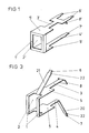
- FIG. 1 of the drawing An embodiment of a cover device for a headlight for motor vehicles, which was assumed in the formation of the preamble of claim 1, is shown in Fig. 1 of the drawing in a perspective view.
- Fig. 1 of the drawing shows a known, substantially U-shaped cover device of a headlight, not shown, for motor vehicles.
- the cover device consists of a cup-shaped sheet metal part produced in the deep-drawing process, the rectangular base 1 'of which forms a web, has a punched-out opening 2' and from whose wall forming the lateral surface two opposite legs 3 'and serving as support arms. 4 'are cut free.
- the legs serving as support arms 3 'and. 4 'adjacent to the floor 1' cover screens 5 'which, in the case of a reflector having a rectangular light outlet opening, shield the upper and lower flats against light rays emerging directly from the filament.
- the leg 3 ' has two cut-out tongues 6' at its free end region and the leg 4 'has a cut-out tongue 7'.
- the tongues 6 'u. 7 ' can be fixed in openings in a lamp holder.
- the leg 3' has a further cover screen 8 'which is angled toward the leg 4' and which shields the scattered light which arises in the base of the glass bulb of an incandescent lamp from the reflector regions adjacent to the lamp holder.
- the light rays emerging directly from the filament of the incandescent lamps are shielded from the upper edge region of the lamp base of the incandescent lamp by the cover screen.
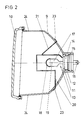
- the reflector 9 of which has a rectangular light outlet opening and is covered by a lens 10.
- the peripheral outer edge of the lens 10 is glued to the reflector edge.
- the reflector 9 is made of a material with low heat resistance, such as plastic.
- the apex opening 11 is surrounded by the reflector neck 12, in which the light bulb 13 with the sleeve-shaped lamp base 14 made of plastic is inserted into the reflector neck 12 from the back of the reflector 9.
- a rubber ring 15 fixed on the lateral surface of the lamp base 14 engages in a circumferential groove on the inside of the reflector neck 12 and fixes the lamp base 14 in the axial direction.
- the lamp base 14 is fixed by the reflector neck 12 which bears at least in sections on the lateral surface of the sleeve-shaped lamp base 14.
- the flat plug connections 16 of the incandescent lamp are fastened to the surface of the lamp base 14 directed towards the rear of the reflector.
- the glass bulb 17 of the incandescent lamp facing the lens has at its free end an opaque cap 18, so that the light rays emerging directly from the filament 19 are shielded from the lens 10.
- An essentially U-shaped covering device is arranged in the interior of the headlight in the vicinity of the incandescent lamp 13 and is produced from a flat sheet metal blank by bending.
- the web 1 of the U-shape is arranged running vertically between the incandescent lamp 13 and the lens 10.
- the legs 3 u. 4 of the U-shape run at a distance above and below the glass bulb 17 of the incandescent lamp.
- the leg 4 arranged below the glass bulb 17 has an end section 20 which is angled towards the lower reflector part and serves as a support arm of the covering device.
- a cut-out tongue 21 is bent toward the upper reflector part, the free cut over the entire web height into the legs 3 and. 4 runs into it.
- This tongue 21, which serves as the second support arm, runs in the light shadow of the leg 3.
- the support arms 3 u arranged above and below the glass bulb of the incandescent lamp. 4 of the cover device have at their free end portions a cut-out tongue 6 u. 7, which are pushed into slot-like openings of the reflector 9 up to the contact surface 22 of the support arms formed by shoulders.
- the support arms are securely attached to the reflector 9.
- the opening 2 created by the free cutting and the bending out of the tongue 21 forming the support arm is widened so close to the side edges of the U-shape that two narrow strips of the web 1 delimiting the opening remain.
- the narrow strips of the web are arched in cross-section.
- legs 3 u. 4 Adjacent to the opening 2, it is arranged above and below the incandescent lamp 13 nete legs 3 u. 4 has a cover screen 5 which shields the light rays emerging directly from the filament 19 of the incandescent lamp from the flattened areas 24 of the reflector 9 which have a rectangular light exit surface and produce scattered light.
- the leg 3 arranged above the glass bulb 17 has a third cover screen 8 which is bent towards the optical axis and which covers the light rays emerging directly from the filament 19 relative to the upper edge region of the lamp base 14 made of plastic and that of the apex opening Shields 11 adjacent reflector areas from the scattered rays generated in the base of the glass bulb 17.
Landscapes
- Engineering & Computer Science (AREA)
- General Engineering & Computer Science (AREA)
- Non-Portable Lighting Devices Or Systems Thereof (AREA)
- Reciprocating, Oscillating Or Vibrating Motors (AREA)
- Lighting Device Outwards From Vehicle And Optical Signal (AREA)
Priority Applications (1)
| Application Number | Priority Date | Filing Date | Title |
|---|---|---|---|
| AT86112452T ATE62188T1 (de) | 1985-11-13 | 1986-09-09 | Scheinwerfer fuer kraftfahrzeuge. |
Applications Claiming Priority (2)
| Application Number | Priority Date | Filing Date | Title |
|---|---|---|---|
| DE3540130 | 1985-11-13 | ||
| DE3540130A DE3540130C1 (de) | 1985-11-13 | 1985-11-13 | Scheinwerfer fuer Kraftfahrzeuge |
Publications (3)
| Publication Number | Publication Date |
|---|---|
| EP0223943A2 true EP0223943A2 (fr) | 1987-06-03 |
| EP0223943A3 EP0223943A3 (en) | 1988-09-14 |
| EP0223943B1 EP0223943B1 (fr) | 1991-04-03 |
Family
ID=6285789
Family Applications (1)
| Application Number | Title | Priority Date | Filing Date |
|---|---|---|---|
| EP19860112452 Expired - Lifetime EP0223943B1 (fr) | 1985-11-13 | 1986-09-09 | Phare pour véhicule |
Country Status (5)
| Country | Link |
|---|---|
| US (1) | US4679127A (fr) |
| EP (1) | EP0223943B1 (fr) |
| AT (1) | ATE62188T1 (fr) |
| DE (1) | DE3540130C1 (fr) |
| ES (1) | ES2003463A6 (fr) |
Cited By (1)
| Publication number | Priority date | Publication date | Assignee | Title |
|---|---|---|---|---|
| FR2704934A1 (fr) * | 1993-05-04 | 1994-11-10 | Valeo Vision | Projecteur de véhicule automobile équipé d'un moyen formant radiateur et d'un élément d'occultation ou de traitement de lumière. |
Families Citing this family (14)
| Publication number | Priority date | Publication date | Assignee | Title |
|---|---|---|---|---|
| JPH0353365Y2 (fr) * | 1987-03-31 | 1991-11-21 | ||
| US4814959A (en) * | 1988-02-25 | 1989-03-21 | Gte Products Corporation | Heat shield for low profile automotive headlight |
| JPH07109721B2 (ja) * | 1990-08-07 | 1995-11-22 | 株式会社小糸製作所 | 車輌用前照灯 |
| DE4227888C1 (de) * | 1992-08-22 | 1993-12-02 | Hella Kg Hueck & Co | Befestigung der Abdeckscheibe am Gehäuse von Kraftfahrzeugscheinwerfern |
| DE4310048C2 (de) * | 1993-03-27 | 1995-07-20 | Hella Kg Hueck & Co | Verfahren zum Befestigen einer lichtdurchlässigen Abschlußscheibe an einem Tragelement einer Leuchte, insbesondere eines Fahrzeugscheinwerfers |
| US5497299A (en) * | 1994-12-12 | 1996-03-05 | General Motors Corporation | Headlamp assembly with hook-in bulb shield |
| JP3176535B2 (ja) * | 1995-06-21 | 2001-06-18 | 株式会社小糸製作所 | 車両用灯具 |
| JP3791626B2 (ja) * | 1995-12-22 | 2006-06-28 | 株式会社小糸製作所 | 車輌用前照灯 |
| US5993035A (en) | 1998-03-09 | 1999-11-30 | Trans Technology Engineered Components, Llc | Combined light shield and heat shield for headlight |
| DE29915292U1 (de) | 1999-09-01 | 1999-11-25 | Hella Kg Hueck & Co, 59557 Lippstadt | Scheinwerfer für Fahrzeuge |
| DE10354992B4 (de) * | 2003-11-25 | 2006-06-08 | GM Global Technology Operations, Inc., Detroit | Leuchtenanordnung |
| DE102004004651B3 (de) | 2004-01-29 | 2005-12-01 | Flowil International Lighting (Holding) B.V. | Lampe für allgemeine Beleuchtungszwecke |
| FR3022978B1 (fr) * | 2014-06-30 | 2018-08-24 | Valeo Vision | Cache d'un module optique pour vehicule automobile |
| JP6595258B2 (ja) | 2015-08-26 | 2019-10-23 | 株式会社小糸製作所 | 灯具 |
Family Cites Families (15)
| Publication number | Priority date | Publication date | Assignee | Title |
|---|---|---|---|---|
| DE7123776U (de) * | 1972-03-02 | Hueck & Co Kg | Fahrzeugscheinwerfer | |
| DE1777817U (de) * | 1956-07-04 | 1958-11-20 | Westfaelische Metall Industrie | Fahrzeugscheinwerfer mit vor der gluehlampe angeordneter blendkappe. |
| GB1180026A (en) * | 1966-06-13 | 1970-02-04 | Lucas Industries Ltd | Vehicle Lamps. |
| FR1577627A (fr) * | 1967-08-16 | 1969-08-08 | ||
| GB1221946A (en) * | 1967-08-16 | 1971-02-10 | Lucas Industries Ltd | Sealed beam lamps |
| FR2098680A5 (fr) * | 1970-07-23 | 1972-03-10 | Sev Marchal | |
| GB1477138A (en) * | 1973-11-14 | 1977-06-22 | British Sealed Beams Ltd | Filament shields |
| FR2312727A1 (fr) * | 1975-05-27 | 1976-12-24 | Cibie Projecteurs | Projecteur pour vehicule automobile |
| US4029985A (en) * | 1976-03-24 | 1977-06-14 | General Electric Company | Rectangular headlamp filament shield |
| FR2396240A1 (fr) * | 1977-07-01 | 1979-01-26 | Cibie Projecteurs | Projecteur croisement-route de grande ouverture pour vehicule automobile |
| US4210841A (en) * | 1978-04-17 | 1980-07-01 | General Electric Company | All plastic headlamp |
| US4280173A (en) * | 1978-06-19 | 1981-07-21 | General Electric Company | Heat shield for plastic headlamp |
| FR2484605A1 (fr) * | 1980-06-12 | 1981-12-18 | Ducellier & Cie | Projecteur pour vehicule automobile |
| FR2500116B1 (fr) * | 1981-02-16 | 1986-06-13 | Seima | Projecteur d'eclairage, notamment pour vehicule automobile |
| DE8430631U1 (de) * | 1984-10-18 | 1985-02-07 | Westfälische Metall Industrie KG Hueck & Co, 4780 Lippstadt | Abgeblendeter fahrzeugscheinwerfer |
-
1985
- 1985-11-13 DE DE3540130A patent/DE3540130C1/de not_active Expired
-
1986
- 1986-09-09 EP EP19860112452 patent/EP0223943B1/fr not_active Expired - Lifetime
- 1986-09-09 AT AT86112452T patent/ATE62188T1/de not_active IP Right Cessation
- 1986-09-22 US US06/910,397 patent/US4679127A/en not_active Expired - Fee Related
- 1986-11-04 ES ES8602899A patent/ES2003463A6/es not_active Expired
Cited By (1)
| Publication number | Priority date | Publication date | Assignee | Title |
|---|---|---|---|---|
| FR2704934A1 (fr) * | 1993-05-04 | 1994-11-10 | Valeo Vision | Projecteur de véhicule automobile équipé d'un moyen formant radiateur et d'un élément d'occultation ou de traitement de lumière. |
Also Published As
| Publication number | Publication date |
|---|---|
| DE3540130C1 (de) | 1987-04-02 |
| ATE62188T1 (de) | 1991-04-15 |
| US4679127A (en) | 1987-07-07 |
| ES2003463A6 (es) | 1988-11-01 |
| EP0223943B1 (fr) | 1991-04-03 |
| EP0223943A3 (en) | 1988-09-14 |
Similar Documents
| Publication | Publication Date | Title |
|---|---|---|
| EP0223943B1 (fr) | Phare pour véhicule | |
| EP0355528B1 (fr) | Phare de croisement | |
| DD247258A5 (de) | Abgeblendeter fahrzeugscheinwerfer nach dem projektionsprinzip | |
| EP0144797A2 (fr) | Pare-soleil pour véhicules | |
| DE2923677A1 (de) | Kunststoff-fahrzeugscheinwerfer mit waermeschild | |
| DE2828856C2 (de) | Scheinwerfer für Kraftfahrzeuge | |
| DE4036031C1 (fr) | ||
| DE1901179A1 (de) | Zweifadenhalogengluehlampe fuer Kraftfahrzeugscheinwerfer | |
| DE19543008B4 (de) | Kraftfahrzeugscheinwerfer mit einem unterteilten Reflektor | |
| DE19602978B4 (de) | Fahrzeug-Scheinwerfer | |
| DE19750494B4 (de) | Verfahren zur Herstellung von Fernlichtscheinwerfern für Fahrzeuge | |
| DE3220704A1 (de) | Einrichtung zur be- und entlueftung des innenraumes von scheinwerfern fuer kraftfahrzeuge | |
| DE19846542C2 (de) | Fahrzeugscheinwerfer mit homogen erscheinender Vorderansicht | |
| DE1197825B (de) | Scheinwerfer fuer Kraftfahrzeuge | |
| EP0548555B1 (fr) | Projecteur pour véhicule | |
| EP0446317B1 (fr) | Ecran paralume | |
| DE19813294C1 (de) | Belüftungsvorrichtung an einem Kraftfahrzeugscheinwerfer und Verfahren zur Herstellung einer Belüftungsvorrichtung an einem Kraftfahrzeugscheinwerfer | |
| EP0636831B1 (fr) | Ecran pour un phare non éblouissant de véhicule automobile | |
| DE19610904B4 (de) | Abblendlichtscheinwerfer für Fahrzeuge | |
| DE3518404C2 (fr) | ||
| DE19624688A1 (de) | Abschattungsvorrichtung für eine Kraftfahrzeugscheinwerferlampe und Herstellungsverfahren für eine derartige Abschattungsvorrichtung | |
| EP1004473A2 (fr) | Unité d'éclairage pour véhicule | |
| DE19838911A1 (de) | Beleuchtungseinrichtung für Fahrzeuge | |
| EP0590454A2 (fr) | Projecteur pour véhicules | |
| DE3633662A1 (de) | Streuscheibe fuer frontscheinwerfer o.dgl. zum einbau in fahrzeuge |
Legal Events
| Date | Code | Title | Description |
|---|---|---|---|
| PUAI | Public reference made under article 153(3) epc to a published international application that has entered the european phase |
Free format text: ORIGINAL CODE: 0009012 |
|
| AK | Designated contracting states |
Kind code of ref document: A2 Designated state(s): AT FR GB IT SE |
|
| PUAL | Search report despatched |
Free format text: ORIGINAL CODE: 0009013 |
|
| AK | Designated contracting states |
Kind code of ref document: A3 Designated state(s): AT FR GB IT SE |
|
| 17P | Request for examination filed |
Effective date: 19890131 |
|
| 17Q | First examination report despatched |
Effective date: 19900917 |
|
| ITF | It: translation for a ep patent filed | ||
| GRAA | (expected) grant |
Free format text: ORIGINAL CODE: 0009210 |
|
| AK | Designated contracting states |
Kind code of ref document: B1 Designated state(s): AT FR GB IT SE |
|
| REF | Corresponds to: |
Ref document number: 62188 Country of ref document: AT Date of ref document: 19910415 Kind code of ref document: T |
|
| ET | Fr: translation filed | ||
| GBT | Gb: translation of ep patent filed (gb section 77(6)(a)/1977) | ||
| PLBE | No opposition filed within time limit |
Free format text: ORIGINAL CODE: 0009261 |
|
| STAA | Information on the status of an ep patent application or granted ep patent |
Free format text: STATUS: NO OPPOSITION FILED WITHIN TIME LIMIT |
|
| 26N | No opposition filed | ||
| PGFP | Annual fee paid to national office [announced via postgrant information from national office to epo] |
Ref country code: SE Payment date: 19940907 Year of fee payment: 9 Ref country code: AT Payment date: 19940907 Year of fee payment: 9 |
|
| EAL | Se: european patent in force in sweden |
Ref document number: 86112452.7 |
|
| PGFP | Annual fee paid to national office [announced via postgrant information from national office to epo] |
Ref country code: GB Payment date: 19950817 Year of fee payment: 10 |
|
| PGFP | Annual fee paid to national office [announced via postgrant information from national office to epo] |
Ref country code: FR Payment date: 19950904 Year of fee payment: 10 |
|
| PG25 | Lapsed in a contracting state [announced via postgrant information from national office to epo] |
Ref country code: AT Effective date: 19950909 |
|
| PG25 | Lapsed in a contracting state [announced via postgrant information from national office to epo] |
Ref country code: SE Effective date: 19950910 |
|
| EUG | Se: european patent has lapsed |
Ref document number: 86112452.7 |
|
| PG25 | Lapsed in a contracting state [announced via postgrant information from national office to epo] |
Ref country code: GB Effective date: 19960909 |
|
| PG25 | Lapsed in a contracting state [announced via postgrant information from national office to epo] |
Ref country code: FR Effective date: 19960930 |
|
| GBPC | Gb: european patent ceased through non-payment of renewal fee |
Effective date: 19960909 |
|
| REG | Reference to a national code |
Ref country code: FR Ref legal event code: ST |
|
| REG | Reference to a national code |
Ref country code: FR Ref legal event code: ST |
|
| PG25 | Lapsed in a contracting state [announced via postgrant information from national office to epo] |
Ref country code: IT Free format text: LAPSE BECAUSE OF NON-PAYMENT OF DUE FEES;WARNING: LAPSES OF ITALIAN PATENTS WITH EFFECTIVE DATE BEFORE 2007 MAY HAVE OCCURRED AT ANY TIME BEFORE 2007. THE CORRECT EFFECTIVE DATE MAY BE DIFFERENT FROM THE ONE RECORDED. Effective date: 20050909 |