EP0224234A2 - Offener, quasi-optischer Resonator für elektromagnetische Millimeter- und Submilllimeterwellen - Google Patents
Offener, quasi-optischer Resonator für elektromagnetische Millimeter- und Submilllimeterwellen Download PDFInfo
- Publication number
- EP0224234A2 EP0224234A2 EP86116277A EP86116277A EP0224234A2 EP 0224234 A2 EP0224234 A2 EP 0224234A2 EP 86116277 A EP86116277 A EP 86116277A EP 86116277 A EP86116277 A EP 86116277A EP 0224234 A2 EP0224234 A2 EP 0224234A2
- Authority
- EP
- European Patent Office
- Prior art keywords
- mirror
- quasi
- open
- optical resonator
- radius
- Prior art date
- Legal status (The legal status is an assumption and is not a legal conclusion. Google has not performed a legal analysis and makes no representation as to the accuracy of the status listed.)
- Granted
Links
Images


Classifications
-
- H—ELECTRICITY
- H01—ELECTRIC ELEMENTS
- H01J—ELECTRIC DISCHARGE TUBES OR DISCHARGE LAMPS
- H01J25/00—Transit-time tubes, e.g. klystrons, travelling-wave tubes, magnetrons
- H01J25/02—Tubes with electron stream modulated in velocity or density in a modulator zone and thereafter giving up energy in an inducing zone, the zones being associated with one or more resonators
- H01J25/025—Tubes with electron stream modulated in velocity or density in a modulator zone and thereafter giving up energy in an inducing zone, the zones being associated with one or more resonators with an electron stream following a helical path
-
- H—ELECTRICITY
- H01—ELECTRIC ELEMENTS
- H01J—ELECTRIC DISCHARGE TUBES OR DISCHARGE LAMPS
- H01J23/00—Details of transit-time tubes of the types covered by group H01J25/00
- H01J23/16—Circuit elements, having distributed capacitance and inductance, structurally associated with the tube and interacting with the discharge
- H01J23/18—Resonators
- H01J23/20—Cavity resonators; Adjustment or tuning thereof
Definitions
- the invention relates to an open, quasi-optical resonator for electromagnetic millimeter and submillimeter waves according to the preamble of claim 1.
- Such a resonator is preferably used in a microwave source, which is known under the term quasi-optical gyrotron and is described, for example, in an article by T.A. Hargeaves et al., Int. J. Electronics 57, 977 (1984) or also in an article A. Perrenoud et al., Int. J. Electronics 57, 985 (1984).
- a high-energy electron beam generated by an electron gun passes through the above-mentioned resonator in the middle between the two concave mirrors. Due to a strong magnetic field oriented parallel to the electron beam axis, the electrons move in a spiral Orbits with an orbital frequency corresponding to the cyclotron frequency. This is directly proportional to the strength of the magnetic field. With a suitable choice of the magnetic field strength, the spiraling electrons in the resonator excite the desired electromagnetic waves in the millimeter or submillimeter range. These are decoupled from the resonator and fed to the output of the gyrotron. An important area of application will be nuclear fusion, where the energy of the waves is used to heat the fusion plasma.
- TEM mnp modes arise in the resonator.
- the indices m and n denote transverse modes, while p stands for longitudinal modes (see also H. Kogelnik, 1966, Modes in Optical Resonators; Lasers, Vol. 1, edited by AK Levine, New York: Marcel Dekker, p. 295).
- TEM oop modes are selected in a gyrotron because they have the lowest diffraction losses. For the sake of simplicity, only such modes will be considered below. Nevertheless, all of the following statements also apply to the more general TEM mnp modes.
- Modes are standing waves in the resonator.
- the surfaces of the concave mirrors are surfaces of the same phase.
- the tangential component of the electric field vector disappears on them.
- the surfaces of the concave mirrors are therefore node surfaces for the modes.
- the concave mirrors have a plurality of mirror surfaces offset in a step-like manner.
- Such modes are preferably formed in such a resonator structure, for which the step-like offset of the individual mirror surfaces relative to one another approximately corresponds to a whole multiple of their half wavelength and for which all mirror surfaces are therefore node surfaces.
- the individual mirror surfaces are offset by one or more whole multiples of half the wavelength ⁇ p / 2 of the desired TEM oop mode, this condition applies precisely to the desired mode.
- it does not apply to the TEM ooq modes adjacent to the desired mode.
- These suffer higher diffraction in the resonator according to the invention loss than in a resonator without a step structure.
- the desired mode TEM oop is preferably excited in the resonator according to the invention.
- the excitation of the desired mode TEM oop in the resonator according to the invention is considerably more efficient than in a resonator without a step structure.
- the total step-like offset of the individual mirror surfaces should be between 6 and 10 half wavelengths ⁇ p / 2 of the desired TEM oop mode.
- the areas of the individual mirror areas are advantageously dimensioned relative to one another such that they have approximately the same energy flow. Slots can be provided for coupling out the electromagnetic waves.
- the open, quasi-optical resonator shown in FIG. 1 consists of two identical, opposed, round concave mirrors 1 and 2. These each have two mirror surfaces 1.1 and 1.2 or 2.1 and 2.2, which are staggered with respect to one another.
- the mirror surfaces 1.1, 1.2, 2.1 and 2.2 are spherically curved with approximately the same radii of curvature R and are adapted to the node surfaces of the standing waves that form in the resonator.
- the mirror surfaces 1.1 and 1.2 on the one hand and the mirror surfaces 2.1 and 2.2 on the other hand are arranged concentrically to one another.
- the inner mirror surfaces 1.1 and 2.1 are designed as continuous, central mirror surfaces. They are surrounded by the outer mirror surfaces 1.2 and 2.2 in a ring.
- the inner mirror surfaces 1.1 and 2.1 limiting radius r 1.1 and r 2.1 corresponds to the inner radius of the outer mirror surfaces 1.2 and 2.2.
- Annular slots 1.3 and 2.3 are provided in the outer mirror surfaces 1.2 and 2.2. These are used to decouple the electromagnetic waves from the resonator.
- the slots 1.3 and 2.3 need not be closed. They can be interrupted by webs, as is evident from the view of one of the concave mirrors 1 or 2 shown in FIG. 2. A mechanical connection between the mirror region lying inside and outside the slots advantageously results via the webs.
- the reference symbols in FIG. 2 correspond to the corresponding reference symbols in FIG. 1.
- the step-like offset h of the mirror surfaces 1.1 and 1.2 on the one hand and the mirror surfaces 2.1 and 2.2 on the other hand, as already explained, amount to at least approximately one or more whole multiples of half the wavelength ⁇ p / 2 of the desired mode. It is preferably between 6 ⁇ p / 2 and 10 ⁇ p / 2.
- the radius a of the concave mirrors 1 and 2 and their mutual distance d should give a Fresnel number N (defined as a2 / ( ⁇ p d) between 0.5 and 10. Furthermore, the mutual distance d of the concave mirrors 1 and 2 should be greater than 50 ⁇ p It is taken with respect to the base areas of the outer mirror surfaces 1.2 and 2.2.
- the surfaces of the mirror surfaces 1.1 and 1.2 or 2.1 and 2.2 are dimensioned relative to one another in such a way that they each have approximately the same energy flow.
- the energy distribution on the mirrors is given by a Gaussian distribution, so that the energy flow in the center of the concave mirror 1, 2 is greater than at the edge. Therefore, the outer mirror surfaces 1.2 and 2.2 are larger in area than the central mirror surfaces 1.1 and 2.1.
- the resonator geometry can be selected for each desired resonance frequency in such a way that an optimum is achieved with regard to diffraction losses and the coupling of the energy through the slots.
- the resonance frequency of 120 GHz with the corresponding wavelength of 2.5 mm.
- this corresponds to a TEM oop with p 287.
- the mutual offset h of the mirror surfaces 1.1 and 1.2 or 2.1 and 2.2 is approximately 8 ⁇ p / 2 and the mutual distance d of the concave mirrors 1 and 2 from each other is 144 ⁇ p .
- the numbers for all radii are the polar angles ⁇ 1, ⁇ 2.1 , ⁇ 2.2 and ⁇ 3, below which the edges of the spherically curved mirror surfaces 1.1 and 2.1 or 2.1 and 2.2 and the edges of the slots 1.3 and 2.3 of their order h mutually offset centers of curvature appear.
- the concave mirror 1 these polar angles and the centers of curvature are shown in FIG. 1.
- the latter are designated M 1.1 and M 1.2 .
- FIG. 3 shows in 6 diagrams a) to f) the results of a numerical simulation of the competition of modes 285 to 298 in their chronological order within a period of approximately 20 usec.
- the modes TEM oo285 to TEM oo289 are plotted along the discrete abscissa in the individual diagrams. The ordinate corresponds to the efficiency E in% of the energy transfer from the electron beam to the individual modes.
- Diagrams a) to f) show the situation in the resonator at successive times. After an initial competition of all modes (mainly in diagrams a) to c), the desired mode TEM oo287 finally prevails and remains practically the only one with an electronic efficiency of 34%.
- a simulation carried out for comparison purposes for a resonator without a step structure showed the dominance of two modes under otherwise identical conditions, namely the modes TEM oo285 and TEM oo286 and this only with an electronic efficiency of 25%.
- Desired modes can thus be generated practically pure and with high efficiency by the invention.
- the concave mirrors need not only have two mirror surfaces offset from one another. You can also be provided with three or even more staggered mirror surfaces.
- the outer or the outer mirror surfaces need not be set back from the central mirror surface or from one another, as in the example in FIG. 1. Reverse dislocation is also possible since it is essentially physically equivalent.
- slots in the concave mirrors for decoupling the electromagnetic waves are not the only possibility, but the electromagnetic power, since the resonator is open, could be collected in a suitable manner by diffraction at the mirror edges.
- a concave mirror is shown in section with three mutually offset mirror surfaces without slots.
- the mirror surfaces are offset from one another in the opposite manner to that of the concave mirrors 1 and 2 according to FIG. 1.
Landscapes
- Lasers (AREA)
- Plasma Technology (AREA)
- Microwave Tubes (AREA)
- Control Of Motors That Do Not Use Commutators (AREA)
Abstract
Description
- Die Erfindung betrifft einen offenen, quasi-optischen Resonator für elektromagnetische Millimeter- und Submillimeterwellen gemäss dem Oberbegriff des Patentanspruchs 1.
- Ein solcher Resonator findet vorzugsweise Verwendung in einer Mikrowellenquelle, welche unter dem Begriff quasi-optisches Gyrotron bekannt und beispielsweise in einem Artikel von T.A. Hargeaves et al., Int. J. Electronics 57, 977 (1984) oder auch in einem Artikel A. Perrenoud et al., Int. J. Electronics 57, 985 (1984) beschrieben ist.
- In dem in den Artikeln beschriebenen Gyrotron durchsetzt ein von einer Elektronenkanone erzeugter Hochenergieelektronenstrahl den genannten Resonator in der Mitte zwischen den beiden Hohlspiegeln. Aufgrund eines parallel zur Elektronenstrahlachse orientierten starken Magnetfeldes bewegen sich die Elektronen auf spiralförmigen Bahnen mit einer der Zyklotronfrequenz entsprechenden Umlauffrequenz. Diese ist direkt proportional zur Stärke des Magnetfeldes. Bei geeigneter Wahl der Magnetfeldstärke regen die spiralenden Elektronen im Resonator die gewünschten elektromagnetischen Wellen im Millimeter- oder Submillimeterbereich an. Diese werden aus dem Resonator ausgekoppelt und dem Ausgang des Gyrotrons zugeführt. Ein wichtiges Anwendungsgebiet wird die Kernfusion sein, wo die Energie der Wellen zur Heizung des Fusionsplasmas dienen soll.
- Im allgemeinen entstehen im Resonator TEMmnp-Moden. Die Indizes m und n bezeichnen Transversalmoden, während p für Longitudinalmoden steht (vgl. auch H. Kogelnik, 1966, Modes in Optical Resonators; Lasers, Vol. 1, herausgegeben von A.K. Levine, New York: Marcel Dekker, S. 295). Normalerweise werden in einem Gyrotron nur die TEMoop-Moden selektiert, weil sie die geringsten Diffraktionsverluste aufweisen. Im folgenden sollen der Einfachheit halber auch nur solche Moden betrachtet werden. Gleichwohl gelten alle nachstehenden Aussagen auch für die allgemeineren TEMmnp-Moden. Damit die thermische Belastung der Hohlspiegel in einem Hochenergie-Gyrotron nicht zu gross wird (die Feldleistung im Resonator kann einige Megawatt betragen), müssen deren Abmessungen wesentlich grösser als die Wellenlänge der elektromagnetischen Strahlung sein. Ein praktischer Wert für p liegt im Bereich zwischen 40 und 400. Das hat allerdings zur Folge, dass der Frequenzabstand zwischen zwei benachbarten Moden TEMoop und TEMoo(p+1) wesentlich kleiner ist als das Instabilitäts-Frequenzband des Gyrotrons. Das wirft das Problem einer Moden-Konkurrenz auf (vgl. z.B. Bondeson et al., Int. J. Infrared Millimeter Waves 9, 309 (1984)).
- Nun ist für die meisten Anwendungen die Reinheit der Moden des Gyrotrons von ausschlaggebender Bedeutung.
- Numerische Berechnungen zeigen, dass unter geeigneten Bedingungen der quasi-optische Resonator auf einer longitudinalen Mode betrieben werden kann. Bei der Wahl eines günstigeren inhomogenen Magnetfeldprofils ist dies nicht mehr der Fall. Die Effizienz des Energieübertrags aus dem Elektronenstrahl auf das elektromagnetische Feld wird dann wegen der nichtlinearen Modenkonkurrenz herabgesetzt.
- Die Erfindung, wie sie in den Patentansprüchen gekennzeichnet ist, löst die Aufgabe, eine Resonatorstruktur der eingangs genannten Art anzugeben, in welcher eine einzelne, gewünschte Longitudinalmode TEMoop gegenüber ihren benachbarten Moden TEMooq (q = p ±1, p ±2, ...) bevorzugt und effizient angeregt wird.
- Moden sind stehende Wellen im Resonator. Für sie sind die Oberflächen der Hohlspiegel Flächen gleicher Phase. Zudem verschwindet auf ihnen die tangentiale Komponente des elektrischen Feldvektors. Die Oberflächen der Hohlspiegel sind daher Knotenflächen für die Moden. Beim erfindungsgemässen Resonator weisen die Hohlspiegel mehrere stufenförmig gegeneinander versetzte Spiegelflächen auf. In einer solchen Resonatorstruktur bilden sich bevorzugt solche Moden aus, für die der stufenförmige Versatz der einzelnen Spiegelflächen gegeneinander annähernd einem ganzen Vielfachen ihrer halben Wellenlänge entspricht und für die deshalb sämtliche Spiegelflächen Knotenflächen sind. In dem nach der Erfindung die einzelnen Spiegelflächen um ein oder mehrere ganze Vielfache der halben Wellenlänge λp/2 der gewünschten TEMoop-Mode versetzt sind, gilt diese Bedingung gerade für die gewünschte Mode. Sie gilt dagegen nicht für die zur gewünschten Mode benachbarten Moden TEMooq. Diese erleiden im erfindungsgemässen Resonator höhere Diffrak tionsverluste als in einem Resonator ohne Stufenstruktur. Durch die höheren Diffraktionsverluste ihrer benachbarten Moden TEMooq wird die gewünschte Mode TEMoop im Resonator nach der Erfindung bevorzugt angeregt. Zudem ist die Anregung der gewünschten Mode TEMoop im erfindungsgemässen Resonator wesentlich effizienter als in einem Resonator ohne Stufenstruktur.
- Optimale Ergebnisse können durch Verwendung der in den abhängigen Patentansprüchen gekennzeichneten Bemessungsvorschriften erzielt werden. Um genügend grosse Diffraktionsverluste der benachbarten Moden zu erreichen, sollte der totale stufenförmige Versatz der einzelnen Spiegelflächen zwischen 6 und 10 halben Wellenlängen λp/2 der gewünschten TEMoop-Mode betragen. Die Flächen der einzelnen Spiegelflächen sind relativ zueinander mit Vorteil so bemessen, dass auf sie annähernd der gleiche Energiefluss entfällt. Für die Auskopplung der elektromagnetischen Wellen können Schlitze vorgesehen werden.
- Im folgenden werden Ausführungsformen der Erfindung unter Bezugnahme auf die Zeichnung beispielsweise erläutert.
- Es zeigt:
- Fig. 1 eine bevorzugte Ausführungsform eines Resonators nach der Erfindung in nicht massstabsgetreuer, geschnittener Darstellung mit zwei Hohlspiegeln mit lediglich jeweils zwei gegeneinander versetzten Spiegelflächen,
- Fig. 2 die Aufsicht auf einen der Hohlspiegel nach Fig. 1,
- Fig. 3 in 6 Diagrammen a) bis f) die zeitliche Entwicklung der Modenkonkurrenz in einem Resonator nach der Art von Fig. 1 und
- Fig. 4 in geschnittener Darstellung einen Hohlspiegel für einen Resonator nach der Erfindung mit drei gegeneinander versetzten Spiegelflächen.
- Der in Fig. 1 dargestellte, offene, quasi-optische Resonator besteht aus zwei identischen, einander gegenüberliegenden, runden Hohlspiegeln 1 und 2. Diese weisen jeweils zwei stufenförmig gegeneinander versetzte Spiegelflächen 1.1 und 1.2 bzw. 2.1 und 2.2 auf. Die Spiegelflächen 1.1, 1.2, 2.1 und 2.2 sind sphärisch gekrümmt mit annähernd gleichen Krümmungsradien R und sind Knotenflächen der sich im Resonator ausbildenden, stehenden Wellen angepasst. Die Spiegelflächen 1.1 und 1.2 einerseits und die Spiegelflächen 2.1 und 2.2 andererseits sind konzentrisch zueinander angeordnet. Die inneren Spiegelflächen 1.1 und 2.1 sind als durchgehende, zentrale Spiegelflächen ausgebildet. Sie sind von den äusseren Spiegelflächen 1.2 und 2.2 ringförmig umgeben. Der die inneren Spiegelflächen 1.1 und 2.1 begrenzende Radius r1.1 bzw. r2.1 entspricht dem inneren Radius der äusseren Spiegelflächen 1.2 bzw. 2.2. In den äusseren Spiegelflächen 1.2 und 2.2 sind ringförmige Schlitze 1.3 und 2.3 vorgesehen. Diese dienen zur Auskopplung der elektromagnetischen Wellen aus dem Resonator. Die Schlitze 1.3 und 2.3 brauchen nicht in sich geschlossen zu sein. Sie können von Stegen unterbrochen sein, wie dies aus der in Fig. 2 dargestellten Aufsicht auf einen der Hohlspiegel 1 oder 2 deutlich wird. Ueber die Stege ergibt sich in vorteilhafter Weise eine mechanische Verbindung zwischen dem innerhalb und ausserhalb der Schlitze liegenden Spiegelbereich. Die Bezugszeichen in Fig. 2 stimmen mit dem entsprechenden Bezugszeichen von Fig. 1 überein.
- Damit sich im Resonator zwischen den Hohlspiegeln 1 und 2 die gewünschte Mode TEMoop gegenüber ihren benachbarten Moden TEMooq bevorzugt ausbilden kann, muss der stufenförmige Versatz h der Spiegelflächen 1.1 und 1.2 einerseits bzw. der Spiegelflächen 2.1 und 2.2 andererseits gegeneinander, wie bereits erläutert, wenigstens annähernd einem oder mehreren ganzen Vielfachen der halben Wellenlänge λp/2 der gewünschten Mode betragen. Vorzugsweise beträgt er zwischen 6 λp/2 und 10 λp/2.
- Der Radius a der Hohlspiegel 1 und 2 sowie ihr gegenseitiger Abstand d sollte eine Fresnelzahl N (definiert als a²/(λpd) zwischen 0.5 und 10 ergeben. Weiter sollte der gegenseitige Abstand d der Hohlspiegel 1 und 2 grösser als 50 λp sein. Er wird bezüglich der Grundflächen der äusseren Spiegelflächen 1.2 bzw. 2.2 genommen.
- Die Flächen der Spiegelflächen 1.1 und 1.2 bzw. 2.1 und 2.2 sind relativ zueinander so bemessen, dass auf sie jeweils annähernd der gleiche Energiefluss entfällt. Dabei sind auch die Schlitze 1.3 bzw. 2.3 sowie ihre durch die Radien r1.3.1 und r1.3.2 bzw. r2.3.1 und r2.3.2 bestimmte Breite und Lage in den äusseren Spiegelflächen 1.2 bzw. 2.2 zu berücksichtigen. Die Energieverteilung auf den Spiegeln ist durch eine gauss'sche Verteilung gegeben, so dass der Energiefluss im Zentrum der Hohlspiegel 1, 2 grösser ist als am Rand. Deshalb sind die äusseren Spiegelflächen 1.2 bzw. 2.2 flächenmässig grösser als die zentralen Spiegelflächen 1.1 bzw. 2.1.
- Grundsätzlich kann für jede gewünschte Resonanzfrequenz die Resonatorgeometrie so gewählt werden, dass man ein Optimum bezüglich Diffraktionsverluste und Auskopplung der Energie durch die Schlitze erreicht. Als Beispiel sei die Resonanzfrequenz von 120 GHz mit der entsprechenden Wellenlänge von 2,5 mm betrachtet. Dies entspricht für den Resonator mit den nachfolgend optimierten Grössen einer TEMoop mit p = 287. Für die die Resonatorgeometrie festlegenden Grössen ergeben sich in diesem Fall die folgenden bevorzugten Werte:
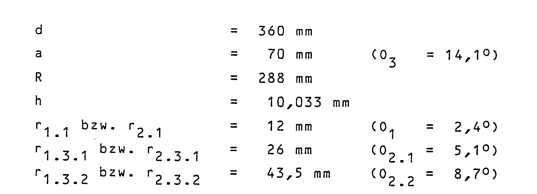
- Im gewählten Beispiel beträgt der gegenseitige Versatz h der Spiegelflächen 1.1 und 1.2 bzw. 2.1 und 2.2 etwa 8 λp/2 und der gegenseitige Abstand d der Hohlspiegel 1 und 2 voneinander 144 λp. Die Zahl N aus der Beziehung N = a²/λpd beträgt hier 5,44. Vorstehend sind hinter den Zahlenangaben für sämtliche Radien noch die Polarwinkel ϑ₁, ϑ2.1, ϑ2.2 und ϑ₃ angegeben, unter denen die Ränder der sphärisch gekrümmten Spiegelflächen 1.1 und 2.1 bzw. 2.1 und 2.2 sowie die Ränder der Schlitze 1.3 bzw. 2.3 von ihren um h gegeneinander versetzten Krümmungsmittelpunkten aus erscheinen. Für den Hohlspiegel 1 sind diese Polarwinkel sowie die Krümmungsmittelpunkte in Fig. 1 eingezeichnet. Letztere sind mit M1.1 und M1.2 bezeichnet.
- Im beispielsweise betrachteten, speziellen Fall ergeben sich folgende Werte für die Diffraktionsverluste der bevorzugten Mode TEMoo287 sowie ihrer benachbarten Moden TEMoo287±1,...,5:

- Fig. 3 zeigt in 6 Diagrammen a) bis f) die Ergebnisse einer numerischen Simulation der Konkurrenz der Moden 285 bis 298 in ihrer zeitlichen Abfolge innerhalb einer Zeitspanne von etwa 20 usec. In den einzelnen Diagrammen sind entlang der diskreten Abszisse die Moden TEMoo285 bis TEMoo289 aufgetragen. Die Ordinate entspricht jeweils der Effizienz E in % des Energieübertrags vom Elektronenstrahl auf die einzelnen Moden. Die Diagramme a) bis f) geben die Situation im Resonator zu aufeinanderfolgenden Zeitpunkten wieder. Nach einer anfänglichen Konkurrenz sämtlicher Moden (vornehmlich in den Diagrammen a) bis c) setzt sich die gewünschte Mode TEMoo287 schliesslich durch und bleibt praktisch als einzige übrig mit einer elektronischen Effizienz von 34 %. Eine zu Vergleichszwecken vorgenommene Simulation für einen Resonator ohne Stufenstruktur ergab unter sonst gleichen Bedingungen die Dominanz zweier Moden, nämlich der Moden TEMoo285 und TEMoo286 und dies auch nur mit einer elektronischen Effizienz von 25 %.
- Durch die Erfindung können also gewünschte Moden praktisch rein und mit hoher Effizienz erzeugt werden.
- Die Hohlspiegel brauchen nach der Erfindung nicht lediglich zwei gegeneinander versetzte Spiegelflächen aufzuweisen. Sie können auch mit drei oder noch mehr gegeneinander versetzten Spiegelflächen versehen sein. Zudem muss die äussere bzw. müssen die äusseren Spiegelflächen gegenüber der zentralen Spiegelfläche sowie gegeneinander nicht, wie im Beispiel von Fig. 1, zurückversetzt sein. Auch eine umgekehrte Versetzung ist möglich, da sie physikalisch im wesentlichen äquivalent ist. Schliesslich sind Schlitze in den Hohlspiegeln zur Auskopplung der elektromagnetischen Wellen nicht die einzige Möglichkeit, sondern die elektromagnetische Leistung könnte, da der Resonator offen ist, durch Diffraktion an den Spiegelrändern in einer geeigneten Weise gesammelt werden.
- In Fig. 4 ist ein Hohlspiegel in geschnittener Darstellung mit drei gegeneinander versetzten Spiegelflächen ohne Schlitze dargestellt. Die Spiegelflächen sind in umgekehrter Weise gegeneinander versetzt wie bei den Holspiegeln 1 und 2 nach Fig. 1.
Claims (10)
N = a² /λpd
genügen, wobei N eine Zahl zwischen 0,5 und 10 ist (Fig. 1).
Applications Claiming Priority (2)
| Application Number | Priority Date | Filing Date | Title |
|---|---|---|---|
| CH509685A CH668865A5 (de) | 1985-11-29 | 1985-11-29 | Offener, quasi-optischer resonator fuer elektromagnetische millimeter- und submillimeterwellen. |
| CH5096/85 | 1985-11-29 |
Publications (3)
| Publication Number | Publication Date |
|---|---|
| EP0224234A2 true EP0224234A2 (de) | 1987-06-03 |
| EP0224234A3 EP0224234A3 (en) | 1989-04-05 |
| EP0224234B1 EP0224234B1 (de) | 1992-06-03 |
Family
ID=4287864
Family Applications (1)
| Application Number | Title | Priority Date | Filing Date |
|---|---|---|---|
| EP19860116277 Expired - Lifetime EP0224234B1 (de) | 1985-11-29 | 1986-11-24 | Offener, quasi-optischer Resonator für elektromagnetische Millimeter- und Submilllimeterwellen |
Country Status (6)
| Country | Link |
|---|---|
| EP (1) | EP0224234B1 (de) |
| JP (1) | JPS62222546A (de) |
| CH (1) | CH668865A5 (de) |
| DE (1) | DE3685556D1 (de) |
| ES (1) | ES2033232T3 (de) |
| GR (1) | GR3005597T3 (de) |
Cited By (3)
| Publication number | Priority date | Publication date | Assignee | Title |
|---|---|---|---|---|
| FR2639153A1 (fr) * | 1988-11-15 | 1990-05-18 | Thomson Tubes Electroniques | Charge hyperfrequence en guide d'onde surdimensionne de faible longueur |
| FR2688937A1 (fr) * | 1992-03-17 | 1993-09-24 | Thomson Tubes Electroniques | Tube hyperfrequence a cavite a miroirs a rendement ameliore. |
| FR2690784A1 (fr) * | 1992-04-30 | 1993-11-05 | Thomson Tubes Electroniques | Tube hyperfréquence à cavité quasi-optique muni d'un dispositif suppresseur d'oscillation parasite. |
Families Citing this family (1)
| Publication number | Priority date | Publication date | Assignee | Title |
|---|---|---|---|---|
| EP0410217A1 (de) * | 1989-07-28 | 1991-01-30 | Asea Brown Boveri Ag | Quasi-optisches Gyrotron |
Family Cites Families (2)
| Publication number | Priority date | Publication date | Assignee | Title |
|---|---|---|---|---|
| BE484122A (de) * | 1947-07-29 | |||
| US3559043A (en) * | 1967-07-03 | 1971-01-26 | Varian Associates | Bimodal cavity resonator and microwave spectrometers using same |
-
1985
- 1985-11-29 CH CH509685A patent/CH668865A5/de not_active IP Right Cessation
-
1986
- 1986-11-24 DE DE8686116277T patent/DE3685556D1/de not_active Expired - Lifetime
- 1986-11-24 ES ES86116277T patent/ES2033232T3/es not_active Expired - Lifetime
- 1986-11-24 EP EP19860116277 patent/EP0224234B1/de not_active Expired - Lifetime
- 1986-11-28 JP JP61282209A patent/JPS62222546A/ja active Pending
-
1992
- 1992-09-03 GR GR920401922T patent/GR3005597T3/el unknown
Cited By (4)
| Publication number | Priority date | Publication date | Assignee | Title |
|---|---|---|---|---|
| FR2639153A1 (fr) * | 1988-11-15 | 1990-05-18 | Thomson Tubes Electroniques | Charge hyperfrequence en guide d'onde surdimensionne de faible longueur |
| EP0369857A1 (de) * | 1988-11-15 | 1990-05-23 | Thomson Tubes Electroniques | Mikrowellen-Abschlusswiderstand in einem kurzen überdimensionierten Wellenleiter |
| FR2688937A1 (fr) * | 1992-03-17 | 1993-09-24 | Thomson Tubes Electroniques | Tube hyperfrequence a cavite a miroirs a rendement ameliore. |
| FR2690784A1 (fr) * | 1992-04-30 | 1993-11-05 | Thomson Tubes Electroniques | Tube hyperfréquence à cavité quasi-optique muni d'un dispositif suppresseur d'oscillation parasite. |
Also Published As
| Publication number | Publication date |
|---|---|
| GR3005597T3 (de) | 1993-06-07 |
| ES2033232T3 (es) | 1993-03-16 |
| EP0224234B1 (de) | 1992-06-03 |
| EP0224234A3 (en) | 1989-04-05 |
| JPS62222546A (ja) | 1987-09-30 |
| DE3685556D1 (de) | 1992-07-09 |
| CH668865A5 (de) | 1989-01-31 |
Similar Documents
| Publication | Publication Date | Title |
|---|---|---|
| DE68908230T2 (de) | Kompakte RF-angeregter Wellenleiter-Gas-Laser-Einrichtung mit verteilten Induktoren. | |
| DE3708314A1 (de) | Mikrowellengepumpter hochdruckgasentladungslaser | |
| DE3687846T2 (de) | Leitungsverteiler/-addierer in radialem wellenleiter und dessen ausfuehrung. | |
| DE2316842B2 (de) | Mehrfrequenzantenne für drei Frequenzbänder | |
| DE68913668T2 (de) | Milimeterwellen-Antenne zur Erzeugung eines Strahles mit einer Gauss-Verteilung. | |
| DE2711494A1 (de) | Breitband-koppelhohlraum-wanderfeldroehre | |
| DE3780736T2 (de) | Aus verschiedenen elementen bestehendes filter der e-flaechenart. | |
| DE3828951C2 (de) | ||
| DE69119273T2 (de) | Dielektrischer Resonator mit Mikrowellenmetallstreifen und mit diesem Resonator ausgerüstete Vorrichtung | |
| EP0224234B1 (de) | Offener, quasi-optischer Resonator für elektromagnetische Millimeter- und Submilllimeterwellen | |
| DE2650388A1 (de) | Rotationssymmetrischer rillenhornstrahler | |
| EP0973227B1 (de) | Dual-Mode Ringresonator | |
| DE69706170T2 (de) | Frequenzumsetzer für millimeterwellen | |
| EP0281858B1 (de) | Hochleistungs-Gyrotron zur Erzeugung elektromagnetischer Millimeter- oder Submillimeterwellen | |
| DE2328632A1 (de) | Antenne, bei der eine strahlschwenkung durch phasensteuerung erfolgt | |
| DE3722128C2 (de) | Mehrfach-gefalteter Laser | |
| DE2833734C2 (de) | ||
| DE69406256T2 (de) | Linearstrahl-Hohlräumeschaltungen mit nicht resonanten RF-Dämpfungsplatten | |
| DE2424679A1 (de) | Breitband-mehrkammer-klystron | |
| EP0125530A2 (de) | Klystrode mit hoher Verstärkung | |
| DE69204866T2 (de) | Modenwandler und Leistungsteiler-Einrichtung für eine Mikrowellenröhre, und Mikrowellenröhre mit einer solchen Einrichtung. | |
| DE2214522A1 (de) | Mikrowellenfenster | |
| EP0177668A1 (de) | Vorrichtung zur Führung eines Elektronenstrahls | |
| DE69132433T2 (de) | Injektionssynchronisierte Oszillatoren | |
| DE1011004B (de) | Wellenleiter fuer Wanderfeldroehren |
Legal Events
| Date | Code | Title | Description |
|---|---|---|---|
| PUAI | Public reference made under article 153(3) epc to a published international application that has entered the european phase |
Free format text: ORIGINAL CODE: 0009012 |
|
| AK | Designated contracting states |
Kind code of ref document: A2 Designated state(s): BE CH DE ES FR GB GR IT LI LU NL SE |
|
| PUAL | Search report despatched |
Free format text: ORIGINAL CODE: 0009013 |
|
| AK | Designated contracting states |
Kind code of ref document: A3 Designated state(s): BE CH DE ES FR GB GR IT LI LU NL SE |
|
| 17P | Request for examination filed |
Effective date: 19890907 |
|
| ITTA | It: last paid annual fee | ||
| 17Q | First examination report despatched |
Effective date: 19911105 |
|
| GRAA | (expected) grant |
Free format text: ORIGINAL CODE: 0009210 |
|
| AK | Designated contracting states |
Kind code of ref document: B1 Designated state(s): BE CH DE ES FR GB GR IT LI LU NL SE |
|
| REF | Corresponds to: |
Ref document number: 3685556 Country of ref document: DE Date of ref document: 19920709 |
|
| ITF | It: translation for a ep patent filed | ||
| ET | Fr: translation filed | ||
| GBT | Gb: translation of ep patent filed (gb section 77(6)(a)/1977) | ||
| PGFP | Annual fee paid to national office [announced via postgrant information from national office to epo] |
Ref country code: FR Payment date: 19921014 Year of fee payment: 7 |
|
| PGFP | Annual fee paid to national office [announced via postgrant information from national office to epo] |
Ref country code: BE Payment date: 19921019 Year of fee payment: 7 |
|
| PGFP | Annual fee paid to national office [announced via postgrant information from national office to epo] |
Ref country code: GB Payment date: 19921022 Year of fee payment: 7 |
|
| PGFP | Annual fee paid to national office [announced via postgrant information from national office to epo] |
Ref country code: SE Payment date: 19921023 Year of fee payment: 7 |
|
| PGFP | Annual fee paid to national office [announced via postgrant information from national office to epo] |
Ref country code: LU Payment date: 19921029 Year of fee payment: 7 |
|
| PGFP | Annual fee paid to national office [announced via postgrant information from national office to epo] |
Ref country code: GR Payment date: 19921111 Year of fee payment: 7 |
|
| PGFP | Annual fee paid to national office [announced via postgrant information from national office to epo] |
Ref country code: ES Payment date: 19921113 Year of fee payment: 7 |
|
| PGFP | Annual fee paid to national office [announced via postgrant information from national office to epo] |
Ref country code: NL Payment date: 19921130 Year of fee payment: 7 |
|
| EPTA | Lu: last paid annual fee | ||
| REG | Reference to a national code |
Ref country code: ES Ref legal event code: FG2A Ref document number: 2033232 Country of ref document: ES Kind code of ref document: T3 |
|
| REG | Reference to a national code |
Ref country code: GR Ref legal event code: FG4A Free format text: 3005597 |
|
| PLBE | No opposition filed within time limit |
Free format text: ORIGINAL CODE: 0009261 |
|
| STAA | Information on the status of an ep patent application or granted ep patent |
Free format text: STATUS: NO OPPOSITION FILED WITHIN TIME LIMIT |
|
| 26N | No opposition filed | ||
| PG25 | Lapsed in a contracting state [announced via postgrant information from national office to epo] |
Ref country code: LU Free format text: LAPSE BECAUSE OF NON-PAYMENT OF DUE FEES Effective date: 19931124 Ref country code: GB Effective date: 19931124 |
|
| PG25 | Lapsed in a contracting state [announced via postgrant information from national office to epo] |
Ref country code: SE Effective date: 19931125 Ref country code: ES Free format text: LAPSE BECAUSE OF NON-PAYMENT OF DUE FEES Effective date: 19931125 |
|
| PG25 | Lapsed in a contracting state [announced via postgrant information from national office to epo] |
Ref country code: BE Effective date: 19931130 |
|
| BERE | Be: lapsed |
Owner name: SCHWEIZERISCHE EIDGENOSSENSCHAFT VERTRETEN DURCH Effective date: 19931130 |
|
| PG25 | Lapsed in a contracting state [announced via postgrant information from national office to epo] |
Ref country code: GR Free format text: THE PATENT HAS BEEN ANNULLED BY A DECISION OF A NATIONAL AUTHORITY Effective date: 19940531 |
|
| PG25 | Lapsed in a contracting state [announced via postgrant information from national office to epo] |
Ref country code: NL Effective date: 19940601 |
|
| NLV4 | Nl: lapsed or anulled due to non-payment of the annual fee | ||
| GBPC | Gb: european patent ceased through non-payment of renewal fee |
Effective date: 19931124 |
|
| PG25 | Lapsed in a contracting state [announced via postgrant information from national office to epo] |
Ref country code: FR Effective date: 19940729 |
|
| REG | Reference to a national code |
Ref country code: FR Ref legal event code: ST |
|
| REG | Reference to a national code |
Ref country code: GR Ref legal event code: MM2A Free format text: 3005597 |
|
| EUG | Se: european patent has lapsed |
Ref document number: 86116277.4 Effective date: 19940610 |
|
| PGFP | Annual fee paid to national office [announced via postgrant information from national office to epo] |
Ref country code: DE Payment date: 20010419 Year of fee payment: 15 |
|
| PG25 | Lapsed in a contracting state [announced via postgrant information from national office to epo] |
Ref country code: DE Free format text: LAPSE BECAUSE OF NON-PAYMENT OF DUE FEES Effective date: 20020702 |
|
| REG | Reference to a national code |
Ref country code: ES Ref legal event code: FD2A Effective date: 19941214 |
|
| PGFP | Annual fee paid to national office [announced via postgrant information from national office to epo] |
Ref country code: CH Payment date: 20051104 Year of fee payment: 20 |
|
| PG25 | Lapsed in a contracting state [announced via postgrant information from national office to epo] |
Ref country code: IT Free format text: LAPSE BECAUSE OF NON-PAYMENT OF DUE FEES;WARNING: LAPSES OF ITALIAN PATENTS WITH EFFECTIVE DATE BEFORE 2007 MAY HAVE OCCURRED AT ANY TIME BEFORE 2007. THE CORRECT EFFECTIVE DATE MAY BE DIFFERENT FROM THE ONE RECORDED. Effective date: 20051124 |
|
| REG | Reference to a national code |
Ref country code: CH Ref legal event code: PL |