EP0224240B1 - Dispositif de commande d'une installation de fabrication de profils structurés - Google Patents
Dispositif de commande d'une installation de fabrication de profils structurés Download PDFInfo
- Publication number
- EP0224240B1 EP0224240B1 EP86116333A EP86116333A EP0224240B1 EP 0224240 B1 EP0224240 B1 EP 0224240B1 EP 86116333 A EP86116333 A EP 86116333A EP 86116333 A EP86116333 A EP 86116333A EP 0224240 B1 EP0224240 B1 EP 0224240B1
- Authority
- EP
- European Patent Office
- Prior art keywords
- light
- field
- till
- fields
- corner
- Prior art date
- Legal status (The legal status is an assumption and is not a legal conclusion. Google has not performed a legal analysis and makes no representation as to the accuracy of the status listed.)
- Expired - Lifetime
Links
- 238000004519 manufacturing process Methods 0.000 title claims description 9
- 238000009434 installation Methods 0.000 title 1
- 239000000463 material Substances 0.000 claims abstract description 56
- 238000001125 extrusion Methods 0.000 claims description 14
- 238000000034 method Methods 0.000 claims description 7
- 239000004033 plastic Substances 0.000 claims description 6
- 229920003023 plastic Polymers 0.000 claims description 6
- 230000001105 regulatory effect Effects 0.000 claims description 2
- 230000008961 swelling Effects 0.000 abstract description 24
- 230000003287 optical effect Effects 0.000 abstract description 8
- 235000012438 extruded product Nutrition 0.000 abstract 1
- 238000012544 monitoring process Methods 0.000 abstract 1
- 238000005259 measurement Methods 0.000 description 10
- 238000001514 detection method Methods 0.000 description 7
- 239000013307 optical fiber Substances 0.000 description 6
- 230000005855 radiation Effects 0.000 description 6
- 230000003595 spectral effect Effects 0.000 description 4
- 238000010521 absorption reaction Methods 0.000 description 3
- 238000001816 cooling Methods 0.000 description 3
- 239000000428 dust Substances 0.000 description 3
- 238000013459 approach Methods 0.000 description 2
- 230000005540 biological transmission Effects 0.000 description 2
- 238000000576 coating method Methods 0.000 description 2
- 230000001276 controlling effect Effects 0.000 description 2
- 238000013461 design Methods 0.000 description 2
- 230000006866 deterioration Effects 0.000 description 2
- 230000005670 electromagnetic radiation Effects 0.000 description 2
- 230000032683 aging Effects 0.000 description 1
- 230000004888 barrier function Effects 0.000 description 1
- 230000015572 biosynthetic process Effects 0.000 description 1
- 239000011248 coating agent Substances 0.000 description 1
- 238000010276 construction Methods 0.000 description 1
- 238000013016 damping Methods 0.000 description 1
- 230000000694 effects Effects 0.000 description 1
- 238000005516 engineering process Methods 0.000 description 1
- 239000000835 fiber Substances 0.000 description 1
- 239000011888 foil Substances 0.000 description 1
- 239000003365 glass fiber Substances 0.000 description 1
- 238000005286 illumination Methods 0.000 description 1
- 230000031700 light absorption Effects 0.000 description 1
- 238000007639 printing Methods 0.000 description 1
- 238000012545 processing Methods 0.000 description 1
- 230000035945 sensitivity Effects 0.000 description 1
- 238000007493 shaping process Methods 0.000 description 1
- 239000007787 solid Substances 0.000 description 1
- 238000011144 upstream manufacturing Methods 0.000 description 1
Images


Classifications
-
- B—PERFORMING OPERATIONS; TRANSPORTING
- B29—WORKING OF PLASTICS; WORKING OF SUBSTANCES IN A PLASTIC STATE IN GENERAL
- B29C—SHAPING OR JOINING OF PLASTICS; SHAPING OF MATERIAL IN A PLASTIC STATE, NOT OTHERWISE PROVIDED FOR; AFTER-TREATMENT OF THE SHAPED PRODUCTS, e.g. REPAIRING
- B29C55/00—Shaping by stretching, e.g. drawing through a die; Apparatus therefor
- B29C55/30—Drawing through a die
-
- B—PERFORMING OPERATIONS; TRANSPORTING
- B29—WORKING OF PLASTICS; WORKING OF SUBSTANCES IN A PLASTIC STATE IN GENERAL
- B29C—SHAPING OR JOINING OF PLASTICS; SHAPING OF MATERIAL IN A PLASTIC STATE, NOT OTHERWISE PROVIDED FOR; AFTER-TREATMENT OF THE SHAPED PRODUCTS, e.g. REPAIRING
- B29C48/00—Extrusion moulding, i.e. expressing the moulding material through a die or nozzle which imparts the desired form; Apparatus therefor
- B29C48/03—Extrusion moulding, i.e. expressing the moulding material through a die or nozzle which imparts the desired form; Apparatus therefor characterised by the shape of the extruded material at extrusion
- B29C48/05—Filamentary, e.g. strands
-
- B—PERFORMING OPERATIONS; TRANSPORTING
- B29—WORKING OF PLASTICS; WORKING OF SUBSTANCES IN A PLASTIC STATE IN GENERAL
- B29C—SHAPING OR JOINING OF PLASTICS; SHAPING OF MATERIAL IN A PLASTIC STATE, NOT OTHERWISE PROVIDED FOR; AFTER-TREATMENT OF THE SHAPED PRODUCTS, e.g. REPAIRING
- B29C48/00—Extrusion moulding, i.e. expressing the moulding material through a die or nozzle which imparts the desired form; Apparatus therefor
- B29C48/03—Extrusion moulding, i.e. expressing the moulding material through a die or nozzle which imparts the desired form; Apparatus therefor characterised by the shape of the extruded material at extrusion
- B29C48/09—Articles with cross-sections having partially or fully enclosed cavities, e.g. pipes or channels
- B29C48/10—Articles with cross-sections having partially or fully enclosed cavities, e.g. pipes or channels flexible, e.g. blown foils
-
- B—PERFORMING OPERATIONS; TRANSPORTING
- B29—WORKING OF PLASTICS; WORKING OF SUBSTANCES IN A PLASTIC STATE IN GENERAL
- B29C—SHAPING OR JOINING OF PLASTICS; SHAPING OF MATERIAL IN A PLASTIC STATE, NOT OTHERWISE PROVIDED FOR; AFTER-TREATMENT OF THE SHAPED PRODUCTS, e.g. REPAIRING
- B29C48/00—Extrusion moulding, i.e. expressing the moulding material through a die or nozzle which imparts the desired form; Apparatus therefor
- B29C48/25—Component parts, details or accessories; Auxiliary operations
- B29C48/88—Thermal treatment of the stream of extruded material, e.g. cooling
- B29C48/90—Thermal treatment of the stream of extruded material, e.g. cooling with calibration or sizing, i.e. combined with fixing or setting of the final dimensions of the extruded article
-
- B—PERFORMING OPERATIONS; TRANSPORTING
- B29—WORKING OF PLASTICS; WORKING OF SUBSTANCES IN A PLASTIC STATE IN GENERAL
- B29C—SHAPING OR JOINING OF PLASTICS; SHAPING OF MATERIAL IN A PLASTIC STATE, NOT OTHERWISE PROVIDED FOR; AFTER-TREATMENT OF THE SHAPED PRODUCTS, e.g. REPAIRING
- B29C48/00—Extrusion moulding, i.e. expressing the moulding material through a die or nozzle which imparts the desired form; Apparatus therefor
- B29C48/25—Component parts, details or accessories; Auxiliary operations
- B29C48/88—Thermal treatment of the stream of extruded material, e.g. cooling
- B29C48/90—Thermal treatment of the stream of extruded material, e.g. cooling with calibration or sizing, i.e. combined with fixing or setting of the final dimensions of the extruded article
- B29C48/908—Thermal treatment of the stream of extruded material, e.g. cooling with calibration or sizing, i.e. combined with fixing or setting of the final dimensions of the extruded article characterised by calibrator surface, e.g. structure or holes for lubrication, cooling or venting
-
- B—PERFORMING OPERATIONS; TRANSPORTING
- B29—WORKING OF PLASTICS; WORKING OF SUBSTANCES IN A PLASTIC STATE IN GENERAL
- B29C—SHAPING OR JOINING OF PLASTICS; SHAPING OF MATERIAL IN A PLASTIC STATE, NOT OTHERWISE PROVIDED FOR; AFTER-TREATMENT OF THE SHAPED PRODUCTS, e.g. REPAIRING
- B29C48/00—Extrusion moulding, i.e. expressing the moulding material through a die or nozzle which imparts the desired form; Apparatus therefor
- B29C48/25—Component parts, details or accessories; Auxiliary operations
- B29C48/88—Thermal treatment of the stream of extruded material, e.g. cooling
- B29C48/919—Thermal treatment of the stream of extruded material, e.g. cooling using a bath, e.g. extruding into an open bath to coagulate or cool the material
-
- B—PERFORMING OPERATIONS; TRANSPORTING
- B29—WORKING OF PLASTICS; WORKING OF SUBSTANCES IN A PLASTIC STATE IN GENERAL
- B29C—SHAPING OR JOINING OF PLASTICS; SHAPING OF MATERIAL IN A PLASTIC STATE, NOT OTHERWISE PROVIDED FOR; AFTER-TREATMENT OF THE SHAPED PRODUCTS, e.g. REPAIRING
- B29C48/00—Extrusion moulding, i.e. expressing the moulding material through a die or nozzle which imparts the desired form; Apparatus therefor
- B29C48/25—Component parts, details or accessories; Auxiliary operations
- B29C48/92—Measuring, controlling or regulating
-
- B—PERFORMING OPERATIONS; TRANSPORTING
- B29—WORKING OF PLASTICS; WORKING OF SUBSTANCES IN A PLASTIC STATE IN GENERAL
- B29C—SHAPING OR JOINING OF PLASTICS; SHAPING OF MATERIAL IN A PLASTIC STATE, NOT OTHERWISE PROVIDED FOR; AFTER-TREATMENT OF THE SHAPED PRODUCTS, e.g. REPAIRING
- B29C2948/00—Indexing scheme relating to extrusion moulding
- B29C2948/92—Measuring, controlling or regulating
- B29C2948/92009—Measured parameter
- B29C2948/92076—Position, e.g. linear or angular
-
- B—PERFORMING OPERATIONS; TRANSPORTING
- B29—WORKING OF PLASTICS; WORKING OF SUBSTANCES IN A PLASTIC STATE IN GENERAL
- B29C—SHAPING OR JOINING OF PLASTICS; SHAPING OF MATERIAL IN A PLASTIC STATE, NOT OTHERWISE PROVIDED FOR; AFTER-TREATMENT OF THE SHAPED PRODUCTS, e.g. REPAIRING
- B29C2948/00—Indexing scheme relating to extrusion moulding
- B29C2948/92—Measuring, controlling or regulating
- B29C2948/92323—Location or phase of measurement
- B29C2948/92428—Calibration, after-treatment, or cooling zone
-
- B—PERFORMING OPERATIONS; TRANSPORTING
- B29—WORKING OF PLASTICS; WORKING OF SUBSTANCES IN A PLASTIC STATE IN GENERAL
- B29C—SHAPING OR JOINING OF PLASTICS; SHAPING OF MATERIAL IN A PLASTIC STATE, NOT OTHERWISE PROVIDED FOR; AFTER-TREATMENT OF THE SHAPED PRODUCTS, e.g. REPAIRING
- B29C2948/00—Indexing scheme relating to extrusion moulding
- B29C2948/92—Measuring, controlling or regulating
- B29C2948/92504—Controlled parameter
- B29C2948/9258—Velocity
-
- B—PERFORMING OPERATIONS; TRANSPORTING
- B29—WORKING OF PLASTICS; WORKING OF SUBSTANCES IN A PLASTIC STATE IN GENERAL
- B29C—SHAPING OR JOINING OF PLASTICS; SHAPING OF MATERIAL IN A PLASTIC STATE, NOT OTHERWISE PROVIDED FOR; AFTER-TREATMENT OF THE SHAPED PRODUCTS, e.g. REPAIRING
- B29C2948/00—Indexing scheme relating to extrusion moulding
- B29C2948/92—Measuring, controlling or regulating
- B29C2948/92504—Controlled parameter
- B29C2948/9258—Velocity
- B29C2948/9259—Angular velocity
-
- B—PERFORMING OPERATIONS; TRANSPORTING
- B29—WORKING OF PLASTICS; WORKING OF SUBSTANCES IN A PLASTIC STATE IN GENERAL
- B29C—SHAPING OR JOINING OF PLASTICS; SHAPING OF MATERIAL IN A PLASTIC STATE, NOT OTHERWISE PROVIDED FOR; AFTER-TREATMENT OF THE SHAPED PRODUCTS, e.g. REPAIRING
- B29C2948/00—Indexing scheme relating to extrusion moulding
- B29C2948/92—Measuring, controlling or regulating
- B29C2948/92819—Location or phase of control
- B29C2948/92857—Extrusion unit
- B29C2948/92876—Feeding, melting, plasticising or pumping zones, e.g. the melt itself
- B29C2948/92885—Screw or gear
-
- B—PERFORMING OPERATIONS; TRANSPORTING
- B29—WORKING OF PLASTICS; WORKING OF SUBSTANCES IN A PLASTIC STATE IN GENERAL
- B29C—SHAPING OR JOINING OF PLASTICS; SHAPING OF MATERIAL IN A PLASTIC STATE, NOT OTHERWISE PROVIDED FOR; AFTER-TREATMENT OF THE SHAPED PRODUCTS, e.g. REPAIRING
- B29C2948/00—Indexing scheme relating to extrusion moulding
- B29C2948/92—Measuring, controlling or regulating
- B29C2948/92819—Location or phase of control
- B29C2948/92933—Conveying, transporting or storage of articles
-
- B—PERFORMING OPERATIONS; TRANSPORTING
- B29—WORKING OF PLASTICS; WORKING OF SUBSTANCES IN A PLASTIC STATE IN GENERAL
- B29C—SHAPING OR JOINING OF PLASTICS; SHAPING OF MATERIAL IN A PLASTIC STATE, NOT OTHERWISE PROVIDED FOR; AFTER-TREATMENT OF THE SHAPED PRODUCTS, e.g. REPAIRING
- B29C48/00—Extrusion moulding, i.e. expressing the moulding material through a die or nozzle which imparts the desired form; Apparatus therefor
- B29C48/25—Component parts, details or accessories; Auxiliary operations
- B29C48/88—Thermal treatment of the stream of extruded material, e.g. cooling
- B29C48/885—External treatment, e.g. by using air rings for cooling tubular films
-
- B—PERFORMING OPERATIONS; TRANSPORTING
- B29—WORKING OF PLASTICS; WORKING OF SUBSTANCES IN A PLASTIC STATE IN GENERAL
- B29C—SHAPING OR JOINING OF PLASTICS; SHAPING OF MATERIAL IN A PLASTIC STATE, NOT OTHERWISE PROVIDED FOR; AFTER-TREATMENT OF THE SHAPED PRODUCTS, e.g. REPAIRING
- B29C48/00—Extrusion moulding, i.e. expressing the moulding material through a die or nozzle which imparts the desired form; Apparatus therefor
- B29C48/25—Component parts, details or accessories; Auxiliary operations
- B29C48/88—Thermal treatment of the stream of extruded material, e.g. cooling
- B29C48/90—Thermal treatment of the stream of extruded material, e.g. cooling with calibration or sizing, i.e. combined with fixing or setting of the final dimensions of the extruded article
- B29C48/904—Thermal treatment of the stream of extruded material, e.g. cooling with calibration or sizing, i.e. combined with fixing or setting of the final dimensions of the extruded article using dry calibration, i.e. no quenching tank, e.g. with water spray for cooling or lubrication
-
- B—PERFORMING OPERATIONS; TRANSPORTING
- B29—WORKING OF PLASTICS; WORKING OF SUBSTANCES IN A PLASTIC STATE IN GENERAL
- B29C—SHAPING OR JOINING OF PLASTICS; SHAPING OF MATERIAL IN A PLASTIC STATE, NOT OTHERWISE PROVIDED FOR; AFTER-TREATMENT OF THE SHAPED PRODUCTS, e.g. REPAIRING
- B29C48/00—Extrusion moulding, i.e. expressing the moulding material through a die or nozzle which imparts the desired form; Apparatus therefor
- B29C48/25—Component parts, details or accessories; Auxiliary operations
- B29C48/88—Thermal treatment of the stream of extruded material, e.g. cooling
- B29C48/911—Cooling
- B29C48/9115—Cooling of hollow articles
- B29C48/912—Cooling of hollow articles of tubular films
Definitions
- the invention relates to a method and a device for controlling a system for the production of extruded profiles, in particular plastic profiles or the like, which contains an extrusion tool and a downstream calibration tool in the material flow, with a measuring head for the contactless optical detection of a material jam or material swelling between the Extrusion nozzle and the calibration tool, which has a light-transmitting surface and a light-receiving surface in a spaced-apart arrangement, at least a plurality of light-guiding elements ending at the latter.
- extrusion dies are used, for example in the form of an extruder with an associated extruder nozzle.
- the stream of material emerging from the extrusion tool is fed to a calibration tool which determines the final external shape of the extrusion profile.
- the calibration tool can have an opening, the cross section of which essentially corresponds to that of the extruder nozzle or is somewhat smaller in order to ensure a shaping effect.
- the space between the extruder nozzle and the calibration tool there is a swelling of material in the area of the extruder nozzle mouth and a material jam in front of the calibration tool.
- the object of the invention serves to optically detect this swelling or this jam for the purpose of controlling the production system.
- a cooling device and a device for pulling off the extruded profile usually follow downstream of the calibration tool.
- the formation of the material swelling or the material jam before the input of the calibration tool can be controlled on the one hand on the basis of the speed at which the extrusion tool works; in particular, the speed of the extruder screw can be regulated in a nozzle extruder.
- the speed at which the trigger device works there is the possibility of influencing the speed at which the trigger device works. In both cases, it is important to record the current size of the material swelling or the material jam before the input of the calibration tool and to compare it with a predetermined target value for the material swelling or the material jam in order to obtain a control signal.
- DE-OS 24 33 242 a device for detecting the current material jam before the entrance of a calibration tool is known, in which a mechanical scanning of the extrusion profile emerging from the extrusion tool takes place.
- DE-OS 32 34 126 proposes a contactless optical detection of the material jam, in which an edge of the extruded profile lies in front of the calibration tool in the beam path between a light emitting surface and a light receiving surface and the light absorption is measured in the extruded profile.
- light transmission surface by means of a plurality of optical fibers ending thereon, which guide the light from a remotely arranged light source, and also to have a plurality of optical fibers end on the light receiving surface, through which the incident light reaches a photodetector.
- light is to be understood as electromagnetic radiation from the visible and neighboring spectral ranges. Infrared radiation is preferably used, which may be detected with a photodiode upstream of a filter. Glass fibers can be used as optical fibers.
- FR-PS 2 346 680 a device for measuring the lateral deviation of a web that migrates transversely to the direction of movement is known.
- This device requires two compensation fields to measure the light transmission on the web, which is used as a difference measurement.
- the cross-section or the shape dimension of an extrudate cannot be recorded with this device, since it can only be used functionally to determine the position of flat objects, such as foils or paper webs.
- DE-A 2 913 410 discloses a light-conducting electrical measuring device for value-based detection of a position of an edge of a sheet on a surface of a sheet-fed rotary printing press. With such a measuring device, only a very imprecise digital measurement is possible. Intermediate steps, i.e. an analog measurement without partial jumps to obtain measurement data, cannot be carried out with this device.
- the object of the invention is to provide a method and a device of the type mentioned which, with an uncomplicated structure, enable a precise, rapid detection of the position of an edge of the extruded profile in the material swelling behind the extruder nozzle or in the material jam in front of the call tool.
- the method according to the invention and the proposed device offers all the advantages of the contactless optical detection of the material swelling behind the extruder nozzle or the material jam in front of the calibration tool.
- the device according to the invention is suitable for detecting the swelling of material directly behind the extruder nozzle in the production of profiles from soft plastics, for example from soft PVC, which was not possible in the conventional devices which rely on material contact, since in the production of soft plastic extrudates no calibration can be used.
- the measurement is carried out in particular without mechanical influence on the extruded profile. It is insensitive to external influences such as vibrations, dust etc., and it enables a robust, largely maintenance-free construction.
- optical fiber optics enables the Attach the light emitting and receiving surface in the immediate vicinity of the material swelling to be detected or the material jam behind the extruder nozzle or directly in front of the entrance of the calibration tool, which minimizes possible interference.
- the measuring head can be kept very narrow so that it also fits into small gaps between the extrusion tool and the calibration tool.
- the light transmitter and detector can be accommodated at some distance from the material swelling or the material jam without spatial constriction, which is also advantageous for temperature reasons. In plastic extrusion technology, temperatures up to approx. 380 ° C can prevail in front of the calibration tool. Suitable light-guiding elements easily withstand this, while the more temperature-sensitive light transmitter and detector arrangement should preferably be located at a cooler location at some distance.
- the inventive division of the light-receiving surface into several fields, each with a plurality of light-guiding elements, enables a quick, precise position detection of an edge of the extruded profile located in the area of material swelling or material jam.
- a logical yes / no signal or digital signal you can first identify the field into which the edge falls, and thus obtain rough information on the size of the material swelling or material jam, based on which you can quickly see strong fluctuations in the swelling or jam can fix.
- the plurality of individual light guide element ends in each field makes it possible to derive a quasi-analog signal for the position of the edge within the field. It is thus possible to precisely determine the edge position and, under substantially stationary operating conditions, to precisely adjust the material swelling or the material jam to the desired setpoint.
- the fields of the light receiving surface can have a rectangular layout and directly adjoin one another. Two parallel rows of fields are preferably arranged next to one another and offset by half a field length. As a result of this staggering of fields, there is always a field in the central area of which the edge of the extruded profile to be detected falls; Due to the field boundaries, there are no gaps or blind spots in the detection area. Furthermore, two logical signals are obtained, each of which identifies a field of the neighboring lines into which the edge of the extruded profile to be measured falls. On the basis of these two signals, a rough position measurement of the edge with the accuracy of half a field division is possible.
- the light receiving surface can contain a compensation field, preferably spaced apart from the other fields, at the level of which no edge of the extruded profile comes to lie during operation, and which serves to detect a reference level of the light intensity.
- a compensation field preferably spaced apart from the other fields, at the level of which no edge of the extruded profile comes to lie during operation, and which serves to detect a reference level of the light intensity.
- fluctuations in the emitted and detected light intensity can be corrected which are not caused by the material swelling or the material jam.
- this compensates for a changing optical damping that occurs when the light guide elements move or deform.
- there is a compensation of fluctuations in the intensity of the light transmitter and the age-related deterioration of the light transmitter and light receiver and last but not least, the optical absorption of coatings, e.g. Compensate for dust on the light emitting and receiving surface.
- the device according to the invention has a high sensitivity and is not susceptible to interference.
- it is also suitable for capturing extruded profiles made of translucent or translucent material, taking into account the different absorption behavior of these materials in different spectral ranges by choosing a suitable light wavelength for the measurement. Further use is made of the fact that the extruded profiles have a greater optical density in the edge area. This technological advance is surprising and volatile in nature.
- the light emitting surface can have an elongated rectangular shape and approximately the same size as the light receiving surface including the compensation field. In this way, good illumination of the light receiving surface is achieved with little design effort.
- FIG. 1 shows schematically the section of a plant for the production of extruded profiles made of plastic.
- An extrusion die 20 can be seen in the form of a die extruder, from the die 22 of which an extruded profile 24 emerges which is shaped in accordance with the die mouth.
- the extruded profile 24 can be a solid profile or a hollow profile of any layout.
- the extruded profile 24 is calibrated in a calibration tool 26 and thereby brought to its final external dimension.
- the calibration tool 26 has an opening which is usually designed essentially in accordance with the nozzle mouth and is possibly somewhat smaller in cross section.
- a cooling section 28 connects to the calibration tool 26.
- a withdrawal device 30 can be seen, which withdraws the extruded profile 24 from the calibration tool 26 and usually transfers it to a cutting and stacking device.
- the extruded extruded profile 24 forms behind the Extruder nozzle 22 a material swell A and before entering the calibration tool 26 a material jam 32.
- a controller with a measuring head 34 is used for this purpose, which is arranged, for example, immediately behind the extruder nozzle or immediately in front of the input of the calibration tool 26. With the measuring head 34, the swelling A which is currently developing or the material dust 32 is detected optically without contact.
- a corresponding measured value of the measuring head 34 is compared with a predetermined target value which corresponds to the desired optimal setting of the material swelling A or the material jam 32, and a corresponding control signal is derived.
- the latter serves to influence suitable operating parameters of the system in order to increase or decrease the actual value of the material swelling A or the material jam 32; in particular, the speed of an extruder screw in the extrusion die 20 and / or the transport speed of the take-off device 30 can be changed.
- the measuring head 34 is connected to a housing 38 via a light guide cable 36.
- the housing 38 contains a light transmitter and a light receiver.
- electromagnetic radiation in the visible spectral range and neighboring spectral ranges i.e. Infrared radiation and ultraviolet radiation can be understood.
- Infrared radiation is preferred.
- uncomplicated radiation sources in particular in the form of light-emitting diodes and lasers, and uncomplicated detectors, for example in the form of photodiodes.
- Infrared radiation can be guided through a conventional optical fiber optic, which has the advantage of good temperature resistance.
- the measuring head 34 has a flat part 40 of rectangular outline, at one end of which there is a cuboid-shaped extension 42.
- the light guide cable 36 enters this at 44.
- the approach 42 is provided with a blind threaded bore 46, or the like for mounting the measuring head 34 on a tripod rod. serves. Further fastening points 48 for the direct attachment of the measuring head 34 to the nozzle 22 or the calibration tool 26 are provided in the area of the flat part 40.
- a rectangular incision 50 is provided on the side, through which the measuring head 34 acquires a fork shape.
- a large number of individual elements of the light guide cable 36 end at the surfaces. The elements are guided from the housing entry surface 44 through the flat part 40 to light emitting surfaces 52 or light receiving surfaces 54, and they can in particular be embedded in the flat part 40.
- the elements terminating at the light emitting surface 52 carry light that they receive from the light emitter in the housing 38; this light is emitted at the ends of the elements towards the light receiving surface 54.
- the elements ending there absorb light and guide it to the light detector in the housing 38, it being possible for a filter to be switched on at a suitable point, in particular immediately in front of the light detector.
- a filter can be used to switch off daylight influences, such as fluctuations in ambient light brightness, etc., which results in a correspondingly increased measurement accuracy.
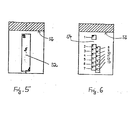
- Figure 5 shows a plan view of the light emitting surface 52. This has an elongated rectangular plan, and it is continuously covered with ends of light guide elements.
- FIG. 6 shows a corresponding top view of the light receiving surface 54. This is divided into a plurality of individual fields, at each of which a plurality of light guide elements end. The fields are square. Near the back 56 of the incision 50 is a single field 1, which is referred to below as the compensation field.
- the compensation field 1 is colinear and at some distance from a row of fields 2, 3, 4, 5, 6, 7, which directly adjoin one another. Directly next to this line is a second line of fields 8, 9, 10, 11, 12, 13, which also directly adjoin one another and are offset by half a field length from fields 2, 3, 4, 5, 6, 7.
- a rectangle enclosing all of the fields 1 to 13 has approximately the same size as the light emitting surface 52.
- the light emitting surface 52 and the light receiving surface 54 form a light barrier which detects an edge of the extruded profile in the area of the material swelling or the material jam 32 in front of the calibration tool 26 during operation.
- the edge comes to lie at the height of the fields 2 to 13, while the compensation field 1 receives a light intensity that is not influenced by the material flow.
- This gives a differential signal which allows fluctuations in the light intensity, aging-related deterioration of the light transmitter or light detector to compensate for optical absorption by a coating which is reflected on the light-transmitting surface 52 or the light-receiving surface 54, etc.
- a first signal is obtained which identifies the field at the level of which the edge of the extruded profile to be detected lies. Due to the staggering of fields 2 to 7 and 8 to 13, there is always a field in the middle of which the edge lies. Normally, one field is identified in each of the two field rows 2 to 7 and 8 to 13, at the level of which the profile edge lies.
- the staggering of the fields allows a grid-based position determination with the accuracy of half a field length. Fast signal processing is possible because a logical yes / no signal or digital signal is sufficient to identify the fields.
- a second signal is derived for fine measurement of the profile edge height, which is characteristic of the height of the profile edge within an identified field. This signal is obtained on the basis of the different light intensity at the light guide elements that end at the field in question.
Landscapes
- Engineering & Computer Science (AREA)
- Mechanical Engineering (AREA)
- Physics & Mathematics (AREA)
- Thermal Sciences (AREA)
- Extrusion Moulding Of Plastics Or The Like (AREA)
- Supports For Plants (AREA)
- Breeding Of Plants And Reproduction By Means Of Culturing (AREA)
- Agricultural Chemicals And Associated Chemicals (AREA)
Claims (7)
Priority Applications (1)
| Application Number | Priority Date | Filing Date | Title |
|---|---|---|---|
| AT86116333T ATE57328T1 (de) | 1985-11-26 | 1986-11-25 | Vorrichtung zur steuerung einer anlage fuer die herstellung von strangprofilen. |
Applications Claiming Priority (2)
| Application Number | Priority Date | Filing Date | Title |
|---|---|---|---|
| DE19853541680 DE3541680A1 (de) | 1985-11-26 | 1985-11-26 | Vorrichtung zur steuerung einer anlage fuer die herstellung von strangprofilen |
| DE3541680 | 1985-11-26 |
Publications (3)
| Publication Number | Publication Date |
|---|---|
| EP0224240A2 EP0224240A2 (fr) | 1987-06-03 |
| EP0224240A3 EP0224240A3 (en) | 1988-01-13 |
| EP0224240B1 true EP0224240B1 (fr) | 1990-10-10 |
Family
ID=6286820
Family Applications (1)
| Application Number | Title | Priority Date | Filing Date |
|---|---|---|---|
| EP86116333A Expired - Lifetime EP0224240B1 (fr) | 1985-11-26 | 1986-11-25 | Dispositif de commande d'une installation de fabrication de profils structurés |
Country Status (4)
| Country | Link |
|---|---|
| US (1) | US4755127A (fr) |
| EP (1) | EP0224240B1 (fr) |
| AT (1) | ATE57328T1 (fr) |
| DE (2) | DE3541680A1 (fr) |
Families Citing this family (14)
| Publication number | Priority date | Publication date | Assignee | Title |
|---|---|---|---|---|
| US5258146A (en) * | 1988-09-26 | 1993-11-02 | 3D Systems, Inc. | Method of and apparatus for measuring and controlling fluid level in stereolithography |
| DE4003696C1 (fr) * | 1990-02-07 | 1990-12-13 | Petzetakis, George Aristovoulos, Piraeus, Gr | |
| US5358673A (en) * | 1990-02-15 | 1994-10-25 | 3D Systems, Inc. | Applicator device and method for dispensing a liquid medium in a laser modeling machine |
| IT1242695B (it) * | 1990-12-20 | 1994-05-17 | Danieli Off Mecc | Dispositivo controllo temperatura dei profili metallici estrusi in fase di estrusione. |
| DE9212406U1 (de) * | 1992-09-15 | 1992-12-17 | Röhm GmbH, 6100 Darmstadt | Vorrichtung zur Ermittlung und Einstellung der Wulsthöhe im Glättwerkspalt bei der Extrusion von Kunststoff-Folien |
| MX9705844A (es) * | 1995-02-01 | 1997-11-29 | 3D Systems Inc | Recubrimiento rapido de objetos tridimensionales con una base en seccion transversal. |
| US5747075A (en) * | 1995-06-07 | 1998-05-05 | Owens-Corning Fiberglas Technology Inc. | Apparatus for resin ipregnated pultrusion |
| FR2739803B1 (fr) * | 1995-10-12 | 1997-12-05 | Induplast Sa | Procede et dispositif de fabrication de structures sandwich a ame thermoplastique |
| EP1378336A1 (fr) * | 2002-07-02 | 2004-01-07 | ATOFINA Research | Evaluation de la transformabilité de polymères par traitement en ligne |
| US8597016B2 (en) | 2005-11-23 | 2013-12-03 | Milgard Manufacturing Incorporated | System for producing pultruded components |
| US8101107B2 (en) | 2005-11-23 | 2012-01-24 | Milgard Manufacturing Incorporated | Method for producing pultruded components |
| US7901762B2 (en) | 2005-11-23 | 2011-03-08 | Milgard Manufacturing Incorporated | Pultruded component |
| US7875675B2 (en) | 2005-11-23 | 2011-01-25 | Milgard Manufacturing Incorporated | Resin for composite structures |
| DE102007025858A1 (de) * | 2007-06-01 | 2008-12-04 | Grünenthal GmbH | Verfahren zur Herstellung einer Arzneimitteldarreichungsform |
Family Cites Families (19)
| Publication number | Priority date | Publication date | Assignee | Title |
|---|---|---|---|---|
| US3531827A (en) * | 1966-05-13 | 1970-10-06 | Harte & Co Inc | Thickness control system for calendering |
| CH487459A (de) * | 1969-01-24 | 1970-03-15 | Lonza Ag | Lichtelektrische Regeleinrichtung |
| CA997035A (en) * | 1971-06-23 | 1976-09-14 | Richard W. Bell | Process for controlling a dimension of a continuous extrudate |
| US4022557A (en) * | 1972-02-18 | 1977-05-10 | Arco Polymers, Inc. | Apparatus for making structural foam profiles |
| US4154563A (en) * | 1972-02-18 | 1979-05-15 | Arco Polymers, Inc. | Apparatus for making structural profiles |
| US3813200A (en) * | 1973-01-22 | 1974-05-28 | Philip Morris Inc | Jam prevention unit for extrusion process apparatus |
| IE39327B1 (en) * | 1973-12-28 | 1978-09-13 | Inst For Ind Res & Standards | Apparatus for the control if the width of a web |
| DE2433242A1 (de) * | 1974-07-11 | 1976-01-29 | Gofini Ag | Verfahren zum betrieb einer anlage zur herstellung eines kunststoffprofilstranges und fuer das verfahren ausgeruestete anlage |
| US4087499A (en) * | 1975-08-07 | 1978-05-02 | The Goodyear Tire & Rubber Company | Method for controlling uniformity in tire tread stock |
| GB1520693A (en) * | 1976-04-01 | 1978-08-09 | Crosfield Electronics Ltd | Detecting lateral position of webs |
| DE2730854A1 (de) * | 1977-07-08 | 1979-01-25 | Martin Hammar | Vorrichtung zum bestimmen des umrisses und zum messen der abmessungen eines gegenstandes |
| US4208126A (en) * | 1978-05-24 | 1980-06-17 | Electric Power Research Institute, Inc. | System for detecting foreign particles or voids in electrical cable insulation and method |
| US4402656A (en) * | 1978-11-30 | 1983-09-06 | Gloucester Engineering Co., Inc. | Control of tubular film size |
| DE2913410C2 (de) * | 1979-04-04 | 1983-08-04 | Koenig & Bauer AG, 8700 Würzburg | Lichtelektrische Meßeinrichtung |
| DE2919472C2 (de) * | 1979-05-15 | 1986-01-16 | Erhardt & Leimer Kg, 8900 Augsburg | Vorrichtung zum kontinuierlichen Extrudieren von Schlauchfolien mit Bahnbreitenregelung |
| DE3033260A1 (de) * | 1979-09-07 | 1981-03-26 | Diffracto Ltd., Windsor, Ontario | Vorrichtung und verfahren zum kontrollieren von werkstuecken |
| US4363966A (en) * | 1980-09-22 | 1982-12-14 | Electric Power Research Institute, Inc. | Detection system for distinguishing between voids and foreign particles in materials and method |
| JPS57110907A (en) * | 1980-12-27 | 1982-07-10 | Yokohama Rubber Co Ltd:The | Measuring method and device for tread shape of tyre |
| DE3234126A1 (de) * | 1982-09-15 | 1984-03-29 | Bernd 6746 Hauenstein Becker | Messkopf zum beruehrungslosen abtasten der staubildung zwischen duese und kalibrierung bei kunststoffprofilfertigungsstrassen |
-
1985
- 1985-11-26 DE DE19853541680 patent/DE3541680A1/de not_active Withdrawn
-
1986
- 1986-11-25 US US06/934,676 patent/US4755127A/en not_active Expired - Fee Related
- 1986-11-25 DE DE8686116333T patent/DE3674885D1/de not_active Expired - Lifetime
- 1986-11-25 EP EP86116333A patent/EP0224240B1/fr not_active Expired - Lifetime
- 1986-11-25 AT AT86116333T patent/ATE57328T1/de not_active IP Right Cessation
Also Published As
| Publication number | Publication date |
|---|---|
| EP0224240A2 (fr) | 1987-06-03 |
| DE3541680A1 (de) | 1987-05-27 |
| DE3674885D1 (de) | 1990-11-15 |
| EP0224240A3 (en) | 1988-01-13 |
| US4755127A (en) | 1988-07-05 |
| ATE57328T1 (de) | 1990-10-15 |
Similar Documents
| Publication | Publication Date | Title |
|---|---|---|
| EP0224240B1 (fr) | Dispositif de commande d'une installation de fabrication de profils structurés | |
| DE102018104705B4 (de) | Verfahren und Vorrichtung zum Vermessen eines rohrförmigen Strangs | |
| DE3045319C2 (fr) | ||
| DE3220785C2 (de) | Vorrichtung zur kontinuierlichen Messung des Anteils der kondensierten Phase in einem Dampfstrom | |
| DE2718807A1 (de) | Geraet zur messung mindestens einer dimension eines objekts und verfahren zum betrieb dieses geraetes | |
| DE4305559A1 (de) | Anordnung und Verfahren zur Konturerkennung von Gegenständen | |
| DE2847610C2 (fr) | ||
| DE2729576A1 (de) | Vorrichtung zur umfangsmessung strangfoermigen gutes | |
| DE202005007089U1 (de) | Sensoranordnung zur optischen Kantendetektierung einer Ware | |
| DE3117942A1 (de) | Verfahren und vorichtung zum messen einer dimension eines objekts in einer fluessigkeit und anwendung des verahrens | |
| EP0144698B1 (fr) | Filière d'extrusion ajustable et procédé pour son utilisation | |
| DE4209546C2 (de) | Vorrichtung zum Ermitteln der Lage der Kante einer laufenden Materialbahn | |
| EP1127267B1 (fr) | Dispositif pour detecter des proprietes d'une bande de materiau transportee dans le sens longitudinal | |
| EP0516992A1 (fr) | Procédé pour déterminer et régler le degré d'orientation de films tubulaires fabriqués dans des installations de soufflage | |
| DE3336659C2 (de) | Meßgerät zum Bestimmen des Profils des Feuchtigkeitsgehalts einer Materialbahn quer zu ihrer Laufrichtung | |
| DE68912961T2 (de) | Erfassung einer Registermarkierung. | |
| EP3285054B1 (fr) | Procédé de détermination de la température d'une barre | |
| DE4238234C2 (de) | Verfahren und Vorrichtung zur Farbflottenverteilung auf einer breiten Warenbahn | |
| DE4300290A1 (fr) | ||
| DE3234126C2 (fr) | ||
| DE19503017A1 (de) | Schneeprofilmeßsonde | |
| DE202018103113U1 (de) | Schnitterfassungsvorrichtung | |
| EP0092504A2 (fr) | Dispositif de mesure fibre-optique avec un capteur et électronique de mesure pour déterminer une position | |
| DE19816359A1 (de) | Fasersensor zum Erkennen von Oberflächenstrukturen | |
| WO1996019728A1 (fr) | Procede et dispositif permettant de mesurer en continu le poids d'un ruban de fibres mobile |
Legal Events
| Date | Code | Title | Description |
|---|---|---|---|
| PUAI | Public reference made under article 153(3) epc to a published international application that has entered the european phase |
Free format text: ORIGINAL CODE: 0009012 |
|
| AK | Designated contracting states |
Kind code of ref document: A2 Designated state(s): AT BE CH DE ES FR GB IT LI NL SE |
|
| PUAL | Search report despatched |
Free format text: ORIGINAL CODE: 0009013 |
|
| AK | Designated contracting states |
Kind code of ref document: A3 Designated state(s): AT BE CH DE ES FR GB IT LI NL SE |
|
| 17P | Request for examination filed |
Effective date: 19880428 |
|
| 17Q | First examination report despatched |
Effective date: 19890213 |
|
| GRAA | (expected) grant |
Free format text: ORIGINAL CODE: 0009210 |
|
| AK | Designated contracting states |
Kind code of ref document: B1 Designated state(s): AT BE CH DE ES FR GB IT LI NL SE |
|
| PG25 | Lapsed in a contracting state [announced via postgrant information from national office to epo] |
Ref country code: SE Effective date: 19901010 Ref country code: NL Effective date: 19901010 Ref country code: BE Effective date: 19901010 |
|
| REF | Corresponds to: |
Ref document number: 57328 Country of ref document: AT Date of ref document: 19901015 Kind code of ref document: T |
|
| REF | Corresponds to: |
Ref document number: 3674885 Country of ref document: DE Date of ref document: 19901115 |
|
| ET | Fr: translation filed | ||
| ITF | It: translation for a ep patent filed | ||
| PG25 | Lapsed in a contracting state [announced via postgrant information from national office to epo] |
Ref country code: ES Free format text: LAPSE BECAUSE OF FAILURE TO SUBMIT A TRANSLATION OF THE DESCRIPTION OR TO PAY THE FEE WITHIN THE PRESCRIBED TIME-LIMIT Effective date: 19910121 |
|
| GBT | Gb: translation of ep patent filed (gb section 77(6)(a)/1977) | ||
| NLV1 | Nl: lapsed or annulled due to failure to fulfill the requirements of art. 29p and 29m of the patents act | ||
| PLBE | No opposition filed within time limit |
Free format text: ORIGINAL CODE: 0009261 |
|
| STAA | Information on the status of an ep patent application or granted ep patent |
Free format text: STATUS: NO OPPOSITION FILED WITHIN TIME LIMIT |
|
| 26N | No opposition filed | ||
| ITTA | It: last paid annual fee | ||
| PGFP | Annual fee paid to national office [announced via postgrant information from national office to epo] |
Ref country code: AT Payment date: 19931117 Year of fee payment: 8 |
|
| PGFP | Annual fee paid to national office [announced via postgrant information from national office to epo] |
Ref country code: GB Payment date: 19931119 Year of fee payment: 8 |
|
| PGFP | Annual fee paid to national office [announced via postgrant information from national office to epo] |
Ref country code: FR Payment date: 19931125 Year of fee payment: 8 |
|
| PGFP | Annual fee paid to national office [announced via postgrant information from national office to epo] |
Ref country code: CH Payment date: 19931206 Year of fee payment: 8 |
|
| PG25 | Lapsed in a contracting state [announced via postgrant information from national office to epo] |
Ref country code: GB Effective date: 19941125 Ref country code: AT Effective date: 19941125 |
|
| PG25 | Lapsed in a contracting state [announced via postgrant information from national office to epo] |
Ref country code: LI Effective date: 19941130 Ref country code: CH Effective date: 19941130 |
|
| PGFP | Annual fee paid to national office [announced via postgrant information from national office to epo] |
Ref country code: DE Payment date: 19950131 Year of fee payment: 9 |
|
| GBPC | Gb: european patent ceased through non-payment of renewal fee |
Effective date: 19941125 |
|
| PG25 | Lapsed in a contracting state [announced via postgrant information from national office to epo] |
Ref country code: FR Effective date: 19950731 |
|
| REG | Reference to a national code |
Ref country code: CH Ref legal event code: PL |
|
| REG | Reference to a national code |
Ref country code: FR Ref legal event code: ST |
|
| PG25 | Lapsed in a contracting state [announced via postgrant information from national office to epo] |
Ref country code: DE Effective date: 19960801 |
|
| PG25 | Lapsed in a contracting state [announced via postgrant information from national office to epo] |
Ref country code: IT Free format text: LAPSE BECAUSE OF NON-PAYMENT OF DUE FEES;WARNING: LAPSES OF ITALIAN PATENTS WITH EFFECTIVE DATE BEFORE 2007 MAY HAVE OCCURRED AT ANY TIME BEFORE 2007. THE CORRECT EFFECTIVE DATE MAY BE DIFFERENT FROM THE ONE RECORDED. Effective date: 20051125 |