EP0224355A2 - Unité de montage pour un corps oscillant - Google Patents
Unité de montage pour un corps oscillant Download PDFInfo
- Publication number
- EP0224355A2 EP0224355A2 EP86308736A EP86308736A EP0224355A2 EP 0224355 A2 EP0224355 A2 EP 0224355A2 EP 86308736 A EP86308736 A EP 86308736A EP 86308736 A EP86308736 A EP 86308736A EP 0224355 A2 EP0224355 A2 EP 0224355A2
- Authority
- EP
- European Patent Office
- Prior art keywords
- fluid
- mount
- chamber
- vacuum
- port
- Prior art date
- Legal status (The legal status is an assumption and is not a legal conclusion. Google has not performed a legal analysis and makes no representation as to the accuracy of the status listed.)
- Withdrawn
Links
Images
Classifications
-
- F—MECHANICAL ENGINEERING; LIGHTING; HEATING; WEAPONS; BLASTING
- F16—ENGINEERING ELEMENTS AND UNITS; GENERAL MEASURES FOR PRODUCING AND MAINTAINING EFFECTIVE FUNCTIONING OF MACHINES OR INSTALLATIONS; THERMAL INSULATION IN GENERAL
- F16F—SPRINGS; SHOCK-ABSORBERS; MEANS FOR DAMPING VIBRATION
- F16F13/00—Units comprising springs of the non-fluid type as well as vibration-dampers, shock-absorbers, or fluid springs
- F16F13/04—Units comprising springs of the non-fluid type as well as vibration-dampers, shock-absorbers, or fluid springs comprising both a plastics spring and a damper, e.g. a friction damper
- F16F13/06—Units comprising springs of the non-fluid type as well as vibration-dampers, shock-absorbers, or fluid springs comprising both a plastics spring and a damper, e.g. a friction damper the damper being a fluid damper, e.g. the plastics spring not forming a part of the wall of the fluid chamber of the damper
- F16F13/08—Units comprising springs of the non-fluid type as well as vibration-dampers, shock-absorbers, or fluid springs comprising both a plastics spring and a damper, e.g. a friction damper the damper being a fluid damper, e.g. the plastics spring not forming a part of the wall of the fluid chamber of the damper the plastics spring forming at least a part of the wall of the fluid chamber of the damper
-
- F—MECHANICAL ENGINEERING; LIGHTING; HEATING; WEAPONS; BLASTING
- F16—ENGINEERING ELEMENTS AND UNITS; GENERAL MEASURES FOR PRODUCING AND MAINTAINING EFFECTIVE FUNCTIONING OF MACHINES OR INSTALLATIONS; THERMAL INSULATION IN GENERAL
- F16F—SPRINGS; SHOCK-ABSORBERS; MEANS FOR DAMPING VIBRATION
- F16F13/00—Units comprising springs of the non-fluid type as well as vibration-dampers, shock-absorbers, or fluid springs
- F16F13/04—Units comprising springs of the non-fluid type as well as vibration-dampers, shock-absorbers, or fluid springs comprising both a plastics spring and a damper, e.g. a friction damper
- F16F13/26—Units comprising springs of the non-fluid type as well as vibration-dampers, shock-absorbers, or fluid springs comprising both a plastics spring and a damper, e.g. a friction damper characterised by adjusting or regulating devices responsive to exterior conditions
-
- F—MECHANICAL ENGINEERING; LIGHTING; HEATING; WEAPONS; BLASTING
- F16—ENGINEERING ELEMENTS AND UNITS; GENERAL MEASURES FOR PRODUCING AND MAINTAINING EFFECTIVE FUNCTIONING OF MACHINES OR INSTALLATIONS; THERMAL INSULATION IN GENERAL
- F16F—SPRINGS; SHOCK-ABSORBERS; MEANS FOR DAMPING VIBRATION
- F16F15/00—Suppression of vibrations in systems; Means or arrangements for avoiding or reducing out-of-balance forces, e.g. due to motion
- F16F15/02—Suppression of vibrations of non-rotating, e.g. reciprocating systems; Suppression of vibrations of rotating systems by use of members not moving with the rotating systems
- F16F15/023—Suppression of vibrations of non-rotating, e.g. reciprocating systems; Suppression of vibrations of rotating systems by use of members not moving with the rotating systems using fluid means
Definitions
- the present invention relates to an apparatus or assembly for mounting a vibrating body to a support structure. More specifically, the invention relates to a mounting device employing a fluid active mount to mount a body or mass subject to vibrational excitations to a frame or support structure, with damping or isolation of such excitations.
- the invention is particularly suitable for use in mounting an internal combustion engine to a motor vehicle frame or body.
- a relatively hard elastomer will provide good damping of high amplitude vibrations, but is relatively ineffective to damp low frequency low amplitude vibrations such as vibrations during engine idle.
- relatively soft elastomeric mounts while better able to isolate low frequency low amplitude vibrations, would be relatively ineffective to damp or isolate higher amplitude vibrations.
- an effective engine mounting device is needed, therefore, to damp or isolate a broad range of vibrational modes and a broad range of vibration frequencies and amplitudes.
- an internal combustion engine will produce relatively low frequency, low amplitude torque pulses during engine idle. Larger amplitude torques are generated during clutch release and rapid acceleration.
- substantially vertical vibrational modes may include low amplitude, high frequency vibrations, such as those generated by powertrain deformations and second order unbalanced inertia forces typical in four cylinder engines.
- a shock absorber is shown to have inner and outer rigid members connected by an elastomeric shear spring and having a main fluid chamber disposed between the two rigid members in fluid communication through a restricted orifice to a second fluid chamber within the inner rigid member.
- a third chamber is provided, specifically an elastomeric bladder within the second fluid chamber, which is selectively chargeable with gas pressure for calibrating the damping characteristics of the device.
- a fourth chamber is provided, specifically an elastomeric diaphragm is included in the main fluid chamber to provide a selectively chargeable gas chamber.
- the engine mount thereof includes an elastic peripheral wall joined with metallic end walls to form a liquid-filled main chamber and a liquid-filled auxiliary chamber.
- the two metallic end walls are rigidly connected.
- the peripheral walls function as thrust springs.
- the partition between the two liquid-filled chambers is said to be either rigid and stationery or moveable.
- An engine mount of this kind is said to be suitable to strongly damp lower frequency, high amplitude oscillations of the engine while allowing high frequency oscillations with low amplitude to pass undamped.
- the elastomeric body, together with the supporting member defines a fluid-filled chamber which is so designed as to expand or contract as the supported and supporting members vibrate toward and away from each other.
- the chambers are said to be filled with hydraulic brake fluid and it is suggested that damping of torsional vibration can be achieved by a fluid flow restrictor valve interposed in the connecting line between the liquid-filled chambers.
- U.S. Patent 1,655.204 to Stevens is directed to a vehicle suspension means employing a fluid communication line between mounting devices.
- an assembly for mounting a vibrating body (10) to a support structure comprising a mount (20,30) and a vacuum accumulator (70), said mount including, a housing ccmprising a substantially rigid wall (21,31) with a first opening therethrough and a first elasticly deformable body (23,33) sealingly bonded to said wall to form a fluid-tight closure of said first opening, said housing defining an elasticly expandable fluid-tight chamber (54) with a first port (26), said mount chamber (54) being in fluid communication, through its said first port (26) via a fluid conduit (41) with said vacuum accumulator (70), means (22,32) for rigidly attaching said rigid wall to one of said vibrating body and said support structures, and means (24,34) for attaching said mount to the one of said body and said support structure to which said rigid wall (21) is not rigidly attached, said attaching means (24,34) being fixedly coupled to said first elastomeric body (23,
- an assembly for mounting an internal combustion engine to a motor vheicle support structure comprises a plurality of mounts and is adapted to damp or isolate vibrations transmitted to or origninating in the engine. At least one of such mounts is as defined above and is connected to a vacuum accumulator as defined above.
- the invention is particularly advantageous in providing a mount having a selectively variable rate. That is, for low amplitude, low frequency vibrations, with the vacuum chamber vented to atmosphere, fluid (generally liquid) within the mount chamber, conduit_and vacuum chamber acts as a spring mass which is believed to resonate at the vibration frequency of the mounted body and thereby to isolate such vibration.
- fluid generally liquid
- conduit_and vacuum chamber acts as a spring mass which is believed to resonate at the vibration frequency of the mounted body and thereby to isolate such vibration.
- a mounting assembly employing one or more mounts as above-described, can be employed to mount an engine in a motor vehicle.
- the mounts can be tuned to isolate from the vehicle body (and, hence, the passenger compartment) the low frequency, low amplitude vibration generated by the engine while idling.
- the mounts are "soft", that is, they have a low apparent rate.
- soft engine mounts would not be used in motor vehicles, notwithstanding the improved passenger comfort while the engine was idling, due to the requirement of a hard, high rate, i.e. relatively stiff engine mount, to withstand and to effectively damp and isolate the large amplitude vibrations and displacements encountered during normal use of a motor vehicle.
- Such large amplitude vibrations include torque displacements during acceleration, vertical displacements due to potholes. etc., and the like.
- it provides not only a low apparent rate to isolate vibrations such as engine idling vibrations, but also a high rate to effectively damp and isolate large amplitude vibrations such as engine vibrations and displacements during acceleration and normal driving of a motor. vehicle.
- a certain high-rate-effect described below is eliminated by applying vacuum to the vacuum accumulator, which prevents or substantially diminishes the spring mass effect of the fluid. That is, it prevents the fluid from resonating.
- above atmospheric pressure can be charged to the vacuum accumulator to similarly prevent or substantially diminish the spring mass effect of the fluid while simultaneously further hardening, i.e. stiffening the mount to increase its apparent rate.
- the invention provides a so-called fluid-active mount assembly in which a liquid within the assembly is selectively employed to produce in the mount a changeable rate.
- the mount is so designed and constructed, that absent the effect of the liquid within the mount assembly the mount is relatively stiff and correspondingly durable to withstand a use environment such as that of an engine mount for a motor vehicle.
- the liquid within the mount assembly acts as a spring mass to change the apparent rate of the mount for a selected vibration frequency. That is, the mount can be tuned such that the spring mass effect of the liquid reduces its apparent rate to effectively isolate vibrations at or near a given frequency such as, for example, to isolate engine idle vibrations from the passenger compartment of a motor vehicle.
- an inherent mount stiffening that is, an increase in the apparent rate of the mount (with a correlative increase in undesirable vibration transmissability) is found to be caused by the same spring mass effect at frequencies somewhat higher than those for which the mount is tuned (such as, for example, at motor vehicle engine vibration frequencies experienced during acceleration from idle to typical driving speeds).
- this undesirable rate increase effect is avoided, without loss of the desirable rate lowering in the frequency range for which the mount is tuned, by use of a vacuum accumulator in fluid communication with the liquid of the mount assembly, as further described and discussed below.
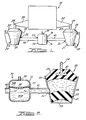
- Figs. 1 and 2 illustrate an engine mounting system comprising an engine 10 supported by a pair of engine mounts 20 and 30 connected to a common vacuum accumulator 70 via conduits 41 and 42, respectively.
- Engine mounts 20 and 30 each comprises a housing having a rigid wall 21,31, respectively, forming a frustro-conical sleeve open at the upper, larger diameter end.
- the housing preferably also has a second opening, as shown, at the lower. smaller diameter end.
- the housings are rigidly attached to a support member 22,32 comprising an element of a vehicle frame or body.
- Each of the engine mount housings further comprises a deformable elastomeric body 23.33 sealingly bonded to the inner surface of the rigid housing wall at the larger diameter end thereof to form a fluid-tight closure of that end of the housing.
- Rigid attachment means 24.34 are fixedly coupled to the elastomeric body 23,33, respectively, and are adapted to fixedly engage a member 25.35 which is rigidly integral with the engine.
- attachment means comprises a hardened metal post which is molded into the elastomeric body with a flange or washer, as shown, connected to the post and embedded in the elastomeric body.
- the housing of the engine mounts each provides a port 26.36, respectively.
- Conduit 41 is sealingly attached to mount 20 at port 26 and conduit 42 is sealingly attached to mount 30 at port 36.
- Such conduits provide fluid communication between the engine mounts and the vacuum accumulator 70.
- Vacuum accumulator 70 comprises housing 72 defining a fluid-tight vacuum chamber 74 with fluid ports 76,77 and a pressure regulation port 78.
- Chamber 74 is in fluid communication with mount 20 through port 76 via conduit 41 and with mount 30 through port 77 via conduit 42 .
- the mount chamber can be either partially liquid and partially gas-filled or, more preferably, entirely liquid filled; but, in any event, both the mount chamber and the the vacuum chamber should be liquid-filled to a level-sufficient to maintain the conduits liquid filled.
- the connections of the conduits to the ports should be fluid-tight.
- each mount can be hsed with its own vacuum accumulator and, alternatively, that more than one mount can be connected to a single vacuum accumulator.
- multiple mounts and vacuum accumulators can be interconnected in any combination meeting the performance requirements and space limitations of the particular application.
- mount assemblies of the invention can be used in conjunction with other types of mounting means to mount a body to a support structure.
- the mount chamber be entirely liquid-filled.
- the liquid therein can entrap gas bubbles which then can travel into the mount chamber. collect at the top of the mount chamber, and form a layer of gas between the fluid in the chamber and the upper elastomeric member. This would affect the apparent rate of the mount and could diminish its ability to isolate and damp vibrations.
- the vacuum accumulator preferably comprises means to prevent or remove any gas layer in the mount chamber. One such means is shown in Fig. 2.
- the vacuum chamber of the accumulator is divided by an elastically deformable diaphragm 79 into an air-tight first sub-chamber 74A in communication with the aforesaid pressure regulating means via port 78 and a fluid-tight second sub-chamber 74B in communication with the aforesaid fluid ports 76,77.
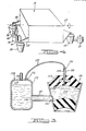
- An alternative, preferred means is illustrated in Fig. 3 , wherein vacuum accumulator 170 comprises'housing 172 defining a fluid-tight chamber 174 with a fluid port 176 and a pressure regulation port 178.
- Chamber 1 74 is in fluid communication with the chamber 122 of mount 120 through port 176 of the vacuum chamber via conduit 141 to port 126 of the mount chamber.
- Rigid attachment means comprises a post 124 fixedly embedded in elastomeric body 123 and is adapted to engage a member (not shown) which is rigidly integral with the engine.
- a bleed valve 130 comprises passageway 132 which extends through post 124 and elastomeric body 123 to the top (gravitationally) of mount chamber 122. Any gas bubbles which pass from the vacuum chamber to the mount chamber via conduit 141 collect at the top of the mount chamber and thence are drawn, each time a vacuum is drawn in the vacuum chamber, via bleed valve conduit 134 through port 136 to the vacuum chamber 174. Any fluid drawn through conduit 134 simply joins the main fluid body in the vacuum chamber. It will be recognized that the fluid level in the vacuum mount would be as high or higher (gravitationally) than the top of the mount chamber according to this embodiment.
- deformable elastomeric body 23 is seen to be sealingly bonded at surface 50 to the frustro-conical wall 21 at the upper, larger diameter open end thereof.
- Attachment means 24 comprises a metal post with an anchoring flange 51 embedded in the elastomeric body 23.
- the attachment post is molded into the elastomer so as to be bonded thereto.
- a second elastomeric body 52 is seen to form a fluid-tight closure of the lower, smaller diameter opening of the wall 21. That is, the second elastomeric body 52 is continuously sealed to the rigid housing wall at surface 53 .
- Conduit 41 is attached to the housing at port 26.
- the two elastomeric bodies 23,52 and the rigid housing wall cooperate to define a chamber 5 4 , which chamber is expandable and contractible upon deformation of the two elastomeric bodies.
- the chamber 51 in response to hydraulic pressure through conduit 41 the chamber 51 can expand and be pressurized.
- the effective rate of the mount would thereby be increased. Accordingly, the rate of the mount can be controlled in this way by controlling a source of pneumatic pressure connected to the vacuum accumulator through port 78.
- mounts for use as an engine mount for a motor vehicle it is highly desirable that the mount be stiff, i.e. have a high spring rate, to withstand the large amplitude vertical and torsional dislocations and vibrations experienced under normal driving conditions.
- mounts having a high rate perform poorly at damping or isolating low frequency vibrations generated by the engine while idling. The result is an undesirably high noise and vibration level in the vehicle passenger compartment.
- a high rate mount is used which nevertheless provides good isolation and damping during engine idling.
- pressure in the vacuum accumulator at or near atmospheric pressure.
- the liquid in the mount chamber, conduit and vacuum accumulator is free to resonate as a single mass, so-called spring mass.
- the liquid in use as an engine mount for a motor vehicle, within a certain pre-selected engine vibration frequency range, the liquid would resonate as a spring mass in such phase relationship that the apparent rate of the mount is substantially lowered for such frequency range.
- the observed effect is to make the mount softer and better able to isolate and damp such vibrations.
- the mounC can be "tuned" such that the fluid column resonates at the frequency of a major component of vibration generated by the engine while idling. In this way, the aforesaid spring mass effect can be maximized for such engine idling vibrations.
- the frequency for which the mount is tuned has been discovered to depend particularly on the volume of liquid in the fluid conduit between the mount and the vacuum accumulator, and on the ratio of the cross-sectional area of the mount chamber (analogizing the elastomeric distortion of the mount chamber to the travel of a piston in a cylinder) to the cross-sectional area of the fluid conduit.
- the fluid conduit dimensions could be about 10 to 20 inches (length) and about 1/2 to 1 inch (bore diameter).
- the aforesaid spring mass effect on the apparent rate of the mount is roughly sinusoidal. It lowers the rate for a certain frequency range, i.e., for a small range of vibration frequencies on either side of the exact frequency for which the mount is tuned. As vibration frequency increases beyond this range, however, the spring mass effect is observed to increase mount stiffness even beyond that which it would have without influence of the fluid column. Thus, in the higher frequency range, (which would, for example, be experienced during acceleration of a motor vehicle from idle to normal driving speeds) the vibration and noise level in the passenger compartment would disadvantageously be increased by the spring mass effect of the fluid column.
- an engine mount according to the invention which is tuned to maximize apparent rate reduction at about 25 hertz might typically have a maximum apparent rate increase effect at about 30 hertz.
- Such apparent rate increase effect would diminish at higher frequencies but might not be entirely eliminated even at 100 hertz, which corresponds to second order engine vibration frequencies at highway driving speeds.
- the application of vacuum to the vacuum chamber disables the spring mass effect such that the mount stiffness is returned substantially to that of the mount without effect of the fluid column.
- the invention can provide advantageously low mount stiffness at engine idle vibration frequencies without the penalty of disadvantageously high mount stiffness at higher vibration frequencies.
- FIG 4 A preferred embodiment of the invention is illustrated schematically in Fig 4, wherein engine 10 is mounted by three engine mounts 20, 30, 60 to a motor vehicle support structure (not shown).
- the engine has a primary roll axis 65 and it can be seen that engine mounts 20 and 30 are positioned in a plane substantially orthogonal to the roll axis.
- the engine mounts are constructed as shown in Fig. 2, having two elastomeric bodies of differing durometer. Upon displacement of the engine, the upper elastomeric body of each engine mounts will be displaced and, thereby contribute to the damping of such displacement of the engine.
- Fluid flow through the conduits between the mounts and the vacuum accumulator also can contribute hydraulic damping.
- the conduits are sized to permit a flow of fluid therethrough at a maximum rate (in response to a large amplitude displacement of the engine), which is insufficient to prevent the build-up of pressure within the mount chamber, then the lower, preferably higher damped, elastomeric body will be deformed by such mount chamber pressure and, so, also contribute to damping of the displacement.
- Proper sizing of the conduit to provide such pressure build-up within the mount is a function of both tube length and diameter and of fluid rheology. It will be within the ability of those skilled in the art in view of the present disclosure to select suitable conduit dimensions and fluid properties to provide such fluid build-up.
- the weight of the engine is supported by the elastomeric material in compression rather than in tension.
- the elastomeric body forming the closure of the larger diameter opening of the housing, in which is embedded the attachment post preferably comprises a material such as rubber or a synthetic elastomeric material having hysteretic damping value of about 6-16 ⁇ of rate, where rate is defined as the pounds force per inch of elastomeric deformation of the material.
- each engine mount might bear, for example, about 100-200 lbs. of engine weight and have a rate of from about 500 lbs.
- the rate is determined not only by the durometer of the elastomeric material, but also by its physical shape, location of attachment, and the direction of forces applied.
- the second elastomeric body that is, the one to which the engine attachment means is not directly attached, can be of higher damped elastomeric material such as for use in motor vehicle engine mounts, for example, styrenebutyl rubber or other synthetic elastomeric material having a hysteretic damping value of about 7-19% of rate.
- styrenebutyl rubber or other synthetic elastomeric material having a hysteretic damping value of about 7-19% of rate.
- Such higher damping elastomer may also damp the resonance from which the aforesaid apparent rate reduction is derived. This would undesirably reduce the amount of apparent rate reduction.
- the fluid conduit interconnecting the engine mount(s) with the vacuum accumulator(s) can be any of a wide variety of materials readily apparent to the skilled of the art, of which many are readily commercially available. Again, the choice of materials and dimensions will depend largely upon the application in which the mounting system is to be used. Typical for use in a motor vehicle in an engine support application would be an inside tube diameter of about 1/4 inch to about 1 inch.
- the conduit can be constructed of the same materials presently used in motor vehicles for hydraulic fluid lines, for example brake lines and the like. Preferably the tube does not significantly expand under pressure, such that high amplitude tortional displacements of a body suspended as shown in F ig.
- the present invention has applicability as an engine support system for motor vehicles and also as a support system for like applications wherein a body subject to vibrations is damped and isolated from a supporting structure.
Landscapes
- Engineering & Computer Science (AREA)
- General Engineering & Computer Science (AREA)
- Mechanical Engineering (AREA)
- Physics & Mathematics (AREA)
- Acoustics & Sound (AREA)
- Aviation & Aerospace Engineering (AREA)
- Combined Devices Of Dampers And Springs (AREA)
- Arrangement Or Mounting Of Propulsion Units For Vehicles (AREA)
- Surgical Instruments (AREA)
- Ultra Sonic Daignosis Equipment (AREA)
- Apparatuses For Generation Of Mechanical Vibrations (AREA)
Applications Claiming Priority (2)
| Application Number | Priority Date | Filing Date | Title |
|---|---|---|---|
| US06/798,086 US4784378A (en) | 1985-11-14 | 1985-11-14 | Vibrating body mounting assembly |
| US798086 | 1985-11-14 |
Publications (2)
| Publication Number | Publication Date |
|---|---|
| EP0224355A2 true EP0224355A2 (fr) | 1987-06-03 |
| EP0224355A3 EP0224355A3 (fr) | 1987-11-11 |
Family
ID=25172514
Family Applications (1)
| Application Number | Title | Priority Date | Filing Date |
|---|---|---|---|
| EP86308736A Withdrawn EP0224355A3 (fr) | 1985-11-14 | 1986-11-10 | Unité de montage pour un corps oscillant |
Country Status (3)
| Country | Link |
|---|---|
| US (1) | US4784378A (fr) |
| EP (1) | EP0224355A3 (fr) |
| JP (1) | JPS62113999A (fr) |
Cited By (6)
| Publication number | Priority date | Publication date | Assignee | Title |
|---|---|---|---|---|
| FR2612329A1 (fr) * | 1987-03-09 | 1988-09-16 | Vibrachoc Sa | Dispositif de suspension autorisant un objet a se deplacer dans un plan |
| EP0372169A3 (en) * | 1988-12-07 | 1990-10-17 | Boge Gmbh | Rubber mounting with hydraulic damping |
| EP0855536A1 (fr) * | 1997-01-16 | 1998-07-29 | Applied Power Inc. | Système de suspension |
| EP1878941A1 (fr) * | 2006-07-10 | 2008-01-16 | Bureau Mertens | Ressort de compression |
| WO2020035278A1 (fr) * | 2018-08-16 | 2020-02-20 | Bayerische Motoren Werke Aktiengesellschaft | Sous-ensemble de fixation pour groupe de véhicule et système modulaire |
| DE102020100816A1 (de) | 2020-01-15 | 2021-07-15 | Audi Aktiengesellschaft | Verfahren und Netzwerk zur Vorkonditionierung zumindest einer Komponente eines Kraftfahrzeugs |
Families Citing this family (37)
| Publication number | Priority date | Publication date | Assignee | Title |
|---|---|---|---|---|
| WO1990014528A1 (fr) * | 1989-05-26 | 1990-11-29 | Regal International, Inc. | Cellule de charge a double piston |
| JPH04302728A (ja) * | 1991-03-29 | 1992-10-26 | Toyoda Gosei Co Ltd | 液封入防振装置 |
| US5388811A (en) * | 1991-07-09 | 1995-02-14 | Lord Corporation | Torque-control system for vehicles cabs and the like |
| USD337555S (en) | 1992-04-14 | 1993-07-20 | Mcnab Robert B | Shock isolation mount |
| JP3016060B2 (ja) * | 1993-04-28 | 2000-03-06 | 本田技研工業株式会社 | 防振マウント装置 |
| US5413320A (en) * | 1993-06-17 | 1995-05-09 | Lord Corporation | Fluid mount for devices such as engines |
| US6386134B1 (en) * | 2000-03-13 | 2002-05-14 | Lockheed Martin Corporation | Elastomeric six degree of freedom isolator |
| DE10026527B4 (de) * | 2000-05-27 | 2008-08-28 | Eras Entwicklung Und Realisation Adaptiver Systeme Gmbh | Verwendung eines elastischen Lagers für eine schwingungsisolierte Lagerung einer Abgasanlage an einem Fahrzeugboden |
| US6491289B1 (en) * | 2000-11-14 | 2002-12-10 | Elyakim Schaap | Oleo-pneumatic shock absorbing system |
| US6676116B2 (en) | 2001-07-05 | 2004-01-13 | The Boeing Company | Elastomeric suspension and mounting system |
| US6609681B2 (en) | 2001-07-05 | 2003-08-26 | The Boeing Company | Method and apparatus for damping vibration |
| RU2298122C1 (ru) * | 2005-11-30 | 2007-04-27 | Государственное образовательное учреждение высшего профессионального образования Томский политехнический университет | Гидропневматический амортизатор |
| EP2507531B1 (fr) * | 2009-12-01 | 2014-04-16 | Bell Helicopter Textron Inc. | Appareil pour améliorer l'isolation contre les vibrations |
| US8844429B2 (en) * | 2011-04-01 | 2014-09-30 | G.E.W. International Corporation Limited | Beverage maker with pump noise attenuator |
| US9551393B2 (en) * | 2014-04-23 | 2017-01-24 | Bell Helicopter Textron Inc. | Rotorcraft vibration isolation systems |
| US10300760B1 (en) | 2015-03-18 | 2019-05-28 | Apple Inc. | Fully-actuated suspension system |
| US11629518B2 (en) | 2017-02-28 | 2023-04-18 | Hummingbird Kinetics LLC | Tuned liquid damper with a membrane liquid-gas interface |
| US10814690B1 (en) | 2017-04-18 | 2020-10-27 | Apple Inc. | Active suspension system with energy storage device |
| CN110997362B (zh) | 2017-05-08 | 2023-07-28 | 苹果公司 | 主动悬架系统 |
| US10899340B1 (en) | 2017-06-21 | 2021-01-26 | Apple Inc. | Vehicle with automated subsystems |
| US11173766B1 (en) | 2017-09-07 | 2021-11-16 | Apple Inc. | Suspension system with locking structure |
| US11065931B1 (en) | 2017-09-15 | 2021-07-20 | Apple Inc. | Active suspension system |
| US11124035B1 (en) | 2017-09-25 | 2021-09-21 | Apple Inc. | Multi-stage active suspension actuator |
| US10960723B1 (en) | 2017-09-26 | 2021-03-30 | Apple Inc. | Wheel-mounted suspension actuators |
| EP3498512B1 (fr) * | 2017-12-12 | 2020-04-08 | C.R.F. Società Consortile per Azioni | Dispositif élastique d'une suspension de moteur de véhicule automobile |
| US11619277B2 (en) * | 2018-05-17 | 2023-04-04 | United States Of America As Represented By The Administrator Of Nasa | Fluid-filled frequency-tunable vibration damper |
| US11285773B1 (en) | 2018-09-12 | 2022-03-29 | Apple Inc. | Control system |
| US11634167B1 (en) | 2018-09-14 | 2023-04-25 | Apple Inc. | Transmitting axial and rotational movement to a hub |
| US11345209B1 (en) | 2019-06-03 | 2022-05-31 | Apple Inc. | Suspension systems |
| US11938922B1 (en) | 2019-09-23 | 2024-03-26 | Apple Inc. | Motion control system |
| US11179991B1 (en) | 2019-09-23 | 2021-11-23 | Apple Inc. | Suspension systems |
| US11707961B1 (en) | 2020-04-28 | 2023-07-25 | Apple Inc. | Actuator with reinforcing structure for torsion resistance |
| US11828339B1 (en) | 2020-07-07 | 2023-11-28 | Apple Inc. | Vibration control system |
| CN117396339A (zh) | 2021-06-07 | 2024-01-12 | 苹果公司 | 质量阻尼器系统 |
| CN113653761B (zh) * | 2021-08-17 | 2023-02-24 | 淄博职业学院 | 发动机液压悬置系统及利用其实现悬置抗振的方法 |
| US12251973B2 (en) | 2022-06-10 | 2025-03-18 | Apple Inc. | Vibration absorber |
| US12168375B1 (en) | 2023-01-26 | 2024-12-17 | Apple Inc. | Motion control system |
Family Cites Families (29)
| Publication number | Priority date | Publication date | Assignee | Title |
|---|---|---|---|---|
| US1655204A (en) * | 1925-10-05 | 1928-01-03 | Stevens Products Company | Cushioning means for vehicles |
| GB341779A (en) * | 1929-04-08 | 1931-01-22 | George Louis Rene Jean Messier | Improved pneumatic and hydraulic shock absorbing apparatus |
| US2038968A (en) * | 1933-12-18 | 1936-04-28 | Gen Motors Corp | Engine mounting |
| US2181073A (en) * | 1937-05-27 | 1939-11-21 | Fred W Schafer | Hydraulic brake system flusher and bleeder |
| US2165501A (en) * | 1938-01-12 | 1939-07-11 | Jr Leon J Nowak | Dash pot |
| GB556307A (en) * | 1942-03-20 | 1943-09-29 | Bendix Ltd | Improvements in or relating to hydraulic braking systems for vehicles or aircraft |
| US2705118A (en) * | 1952-01-30 | 1955-03-29 | Lord Mfg Co | Mounting system |
| GB931300A (en) * | 1959-12-23 | 1963-07-17 | Wilhelm Ley | Improvements in hydropneumatic stabilizers and spring suspension devices for motor vehicles |
| DK116700A (fr) * | 1963-07-12 | |||
| US3363893A (en) * | 1965-02-04 | 1968-01-16 | Girling Ltd | Vehicle suspension device |
| FR1494326A (fr) * | 1966-07-29 | 1967-09-08 | Pied de suspension pivotant à suspension élastiquement compensée et à commande hydraulique | |
| DE1912781C3 (de) * | 1969-03-13 | 1974-08-15 | Fichtel & Sachs Ag, 8720 Schweinfurt | Hydropneumatischer Stoßdämpfer mit ventilgesteuertem Entlüftungssystem |
| FR2255508B1 (fr) * | 1973-12-21 | 1976-10-08 | Vibrachoc Sa | |
| US4153227A (en) * | 1975-11-28 | 1979-05-08 | Gamaunt Roger L | Fluid self-centering vibration and shock mount |
| FR2357790A1 (fr) * | 1976-04-27 | 1978-02-03 | Boge Gmbh | Support de moteur, elastique, a amortissement hydraulique, notamment pour vehicule a moteur |
| DE2727244C2 (de) * | 1976-06-30 | 1990-06-21 | Automobiles Peugeot, 75116 Paris | Gummifeder mit Flüssigkeitsfüllung |
| FR2364373A1 (fr) * | 1976-09-09 | 1978-04-07 | Peugeot | Dispositif de suspension pour machine tournante |
| DE2712641A1 (de) * | 1977-03-23 | 1978-09-28 | Phoenix Gummiwerke Ag | Elastisches lager fuer kraftfahrzeugmotore |
| DE2802896C2 (de) * | 1978-01-24 | 1982-09-23 | Audi Nsu Auto Union Ag, 7107 Neckarsulm | Gummilager mit hydraulischer Dämpfung |
| JPS55123033A (en) * | 1979-03-14 | 1980-09-22 | Mitsubishi Heavy Ind Ltd | Vibration-proof mount |
| US4352487A (en) * | 1980-11-18 | 1982-10-05 | Gould Inc. | Viscous spring damper |
| FR2522759A1 (fr) * | 1982-03-03 | 1983-09-09 | Hutchinson | Perfectionnements aux amortisseurs hydrauliques a membrane |
| DE3245653C2 (de) * | 1982-12-09 | 1986-11-06 | Metzeler Kautschuk GmbH, 8000 München | Zweikammer-Motorlager mit hydraulischer Dämpfung |
| JPS59144839A (ja) * | 1983-02-04 | 1984-08-20 | Toyota Motor Corp | 防振ゴム装置 |
| FR2544820B1 (fr) * | 1983-04-22 | 1985-06-21 | Caoutchouc Manuf Plastique | Support moteur a depression |
| JPS60192195A (ja) * | 1984-03-13 | 1985-09-30 | 日産自動車株式会社 | パワ−ユニツトマウント装置 |
| DE3419851A1 (de) * | 1984-05-28 | 1985-11-28 | Continental Gummi-Werke Ag, 3000 Hannover | Hydraulisch gedaempftes lager |
| DE3441592A1 (de) * | 1984-11-14 | 1986-05-15 | Continental Gummi-Werke Ag, 3000 Hannover | Hydraulisch gedaempftes elastisches lager |
| US4679759A (en) * | 1984-12-24 | 1987-07-14 | Ford Motor Company | Assembly for mounting a vibrating body |
-
1985
- 1985-11-14 US US06/798,086 patent/US4784378A/en not_active Expired - Lifetime
-
1986
- 1986-11-10 EP EP86308736A patent/EP0224355A3/fr not_active Withdrawn
- 1986-11-13 JP JP61268809A patent/JPS62113999A/ja active Pending
Cited By (9)
| Publication number | Priority date | Publication date | Assignee | Title |
|---|---|---|---|---|
| FR2612329A1 (fr) * | 1987-03-09 | 1988-09-16 | Vibrachoc Sa | Dispositif de suspension autorisant un objet a se deplacer dans un plan |
| EP0372169A3 (en) * | 1988-12-07 | 1990-10-17 | Boge Gmbh | Rubber mounting with hydraulic damping |
| EP0855536A1 (fr) * | 1997-01-16 | 1998-07-29 | Applied Power Inc. | Système de suspension |
| EP1878941A1 (fr) * | 2006-07-10 | 2008-01-16 | Bureau Mertens | Ressort de compression |
| WO2020035278A1 (fr) * | 2018-08-16 | 2020-02-20 | Bayerische Motoren Werke Aktiengesellschaft | Sous-ensemble de fixation pour groupe de véhicule et système modulaire |
| US12222014B2 (en) | 2018-08-16 | 2025-02-11 | Bayerische Motoren Werke Aktiengesellschaft | Vehicle unit fastening subassembly and modular system |
| DE102020100816A1 (de) | 2020-01-15 | 2021-07-15 | Audi Aktiengesellschaft | Verfahren und Netzwerk zur Vorkonditionierung zumindest einer Komponente eines Kraftfahrzeugs |
| WO2021144051A1 (fr) | 2020-01-15 | 2021-07-22 | Audi Ag | Procédé et réseau de pré-conditionnement d'au moins un composant d'un véhicule automobile |
| US12084076B2 (en) | 2020-01-15 | 2024-09-10 | Audi Ag | Method and network for pre-conditioning at least one component of a motor vehicle |
Also Published As
| Publication number | Publication date |
|---|---|
| US4784378A (en) | 1988-11-15 |
| EP0224355A3 (fr) | 1987-11-11 |
| JPS62113999A (ja) | 1987-05-25 |
Similar Documents
| Publication | Publication Date | Title |
|---|---|---|
| US4784378A (en) | Vibrating body mounting assembly | |
| US4420060A (en) | Engine mount arrangement | |
| US4199128A (en) | Vibration absorbing elastomeric mount with hydraulic damping | |
| CA1301787C (fr) | Amortisseur en elastomere rempli de fluide | |
| JP4330437B2 (ja) | 流体封入式防振装置 | |
| CN102537195B (zh) | 全解耦液压扭矩支柱 | |
| JPS63265715A (ja) | サスペンション用減衰力発生装置およびそれの作動制御装置 | |
| JPH04224333A (ja) | ブッシュタイプの制振装置及びブッシュタイプの液体充填制振装置 | |
| US5782462A (en) | Hydraulically damped powertrain mount | |
| US4679759A (en) | Assembly for mounting a vibrating body | |
| JP2583145B2 (ja) | 流体封入型防振装置 | |
| US4767107A (en) | Central suspension hydroelastic mount, in particular for the suspension of a motor-vehicle motor-drive unit | |
| EP0178652A2 (fr) | Unité pour l'amortissement de vibrations du type à fluide | |
| US5215294A (en) | Fluid-filled elastic mount having air chamber for absorbing pressure change in fluid chamber filled with highly viscous fluid | |
| US4679779A (en) | Hydraulic mount | |
| US20060151929A1 (en) | Elastomeric/hydraulic vibration isolator with adjustable damping | |
| US5816566A (en) | Viscous fluid mount | |
| EP0834674A2 (fr) | Arrangement pour le support de moteurs | |
| JPS61278639A (ja) | 液体封入式防振体 | |
| EP0430620B1 (fr) | Entretoise | |
| JP2604708B2 (ja) | ダイアフラム形空気ばね | |
| JPH0771506A (ja) | Ff型自動車用エンジン支持装置 | |
| JP4046203B2 (ja) | 液体封入式空気ばね | |
| JPH0434018B2 (fr) | ||
| JPH032089B2 (fr) |
Legal Events
| Date | Code | Title | Description |
|---|---|---|---|
| PUAI | Public reference made under article 153(3) epc to a published international application that has entered the european phase |
Free format text: ORIGINAL CODE: 0009012 |
|
| AK | Designated contracting states |
Kind code of ref document: A2 Designated state(s): DE ES FR GB |
|
| RIN1 | Information on inventor provided before grant (corrected) |
Inventor name: FORD, DAVID M. |
|
| PUAL | Search report despatched |
Free format text: ORIGINAL CODE: 0009013 |
|
| AK | Designated contracting states |
Kind code of ref document: A3 Designated state(s): DE ES FR GB |
|
| 17P | Request for examination filed |
Effective date: 19880421 |
|
| 17Q | First examination report despatched |
Effective date: 19890208 |
|
| STAA | Information on the status of an ep patent application or granted ep patent |
Free format text: STATUS: THE APPLICATION IS DEEMED TO BE WITHDRAWN |
|
| 18D | Application deemed to be withdrawn |
Effective date: 19891020 |
|
| RIN1 | Information on inventor provided before grant (corrected) |
Inventor name: FORD, DAVID M. |