EP0224371A2 - Fraise rotative - Google Patents
Fraise rotative Download PDFInfo
- Publication number
- EP0224371A2 EP0224371A2 EP86308996A EP86308996A EP0224371A2 EP 0224371 A2 EP0224371 A2 EP 0224371A2 EP 86308996 A EP86308996 A EP 86308996A EP 86308996 A EP86308996 A EP 86308996A EP 0224371 A2 EP0224371 A2 EP 0224371A2
- Authority
- EP
- European Patent Office
- Prior art keywords
- tilling
- rotary
- cutter
- center
- rotary shaft
- Prior art date
- Legal status (The legal status is an assumption and is not a legal conclusion. Google has not performed a legal analysis and makes no representation as to the accuracy of the status listed.)
- Withdrawn
Links
Images

Classifications
-
- A—HUMAN NECESSITIES
- A01—AGRICULTURE; FORESTRY; ANIMAL HUSBANDRY; HUNTING; TRAPPING; FISHING
- A01B—SOIL WORKING IN AGRICULTURE OR FORESTRY; PARTS, DETAILS, OR ACCESSORIES OF AGRICULTURAL MACHINES OR IMPLEMENTS, IN GENERAL
- A01B33/00—Tilling implements with rotary driven tools, e.g. in combination with fertiliser distributors or seeders, with grubbing chains, with sloping axles, with driven discs
- A01B33/08—Tools; Details, e.g. adaptations of transmissions or gearings
- A01B33/10—Structural or functional features of the tools ; Theoretical aspects of the cutting action
- A01B33/103—Structural or functional features of the tools ; Theoretical aspects of the cutting action the rotating shaft being oriented horizontally
-
- A—HUMAN NECESSITIES
- A01—AGRICULTURE; FORESTRY; ANIMAL HUSBANDRY; HUNTING; TRAPPING; FISHING
- A01D—HARVESTING; MOWING
- A01D34/00—Mowers; Mowing apparatus of harvesters
- A01D34/01—Mowers; Mowing apparatus of harvesters characterised by features relating to the type of cutting apparatus
- A01D34/412—Mowers; Mowing apparatus of harvesters characterised by features relating to the type of cutting apparatus having rotating cutters
- A01D34/42—Mowers; Mowing apparatus of harvesters characterised by features relating to the type of cutting apparatus having rotating cutters having cutters rotating about a horizontal axis, e.g. cutting-cylinders
- A01D34/52—Cutting apparatus
- A01D34/535—Cutting apparatus with cutting members pivotally attached to the rotating axle, e.g. flails
Definitions
- the present invention relates to a rotary tilling device having a rotary cutting device.
- the rotary cutters in such a rotary cutting device rotate downwardly or upwardly in the soil to break up the surface soil.
- the conventional rotary tilling device is used only for cultivating the soil and is not constructed to perform other work, such as mowing, for example of grass.
- each cutter is rotatably mounted on a supporting member and held at an angular position when tilling.
- soil and mud stick to the periphery of a lower portion of the cutter and to other portions in the device.
- the stuck soil and mud can prevent the cutter from rotating to a proper position for mowing when the cutter is rotated in the opposite direction. Accordingly, desirable cutting operation is not performed.
- the present invention seeks to provide a rotary tilling device which may perform a mowing operation without the obstace of stuck soil and mud.
- the present invention also seeks to provide a tilling device in which mud and soil clogged between the cutters and supporting members during a tilling operation fall off easily so that the cutters are freely rotated during a mowing operation.
- a rotary tilling device comprising, a rotary shaft rotatably supported on frame means, a plurality of supporting members secured to the rotary shaft, at least two cutters rotatably mounted on each of the supporting members at opposite positions thereof, holding means provided on the supporting member for holding the cutter in the tilling (soil cutting) position and for releasing the cutter in the mowing (grass cutting) position, and tranmsitting means for transmitting power of a tractor to the rotary shaft to rotate it.
- Each cutter has a vertical portion,' a base end portion at which the cutter is rotatable about a first center, and a lateral portion bending at another end of the vertical portion in the axial direction of the rotary shaft, and having a soil cutting edge and a grass cutting edge on sides of both the vertical and lateral portions.
- the base end portion has an arcuated periphery about a second center. The first center is deflected from said second center towards the soil cutting edge, so that, in a grass cutting position, the arcuated periphery is located in a more outer position than its position in a soil cutting position.
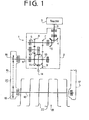
- a rotary tilling device 1 is adapted to be drawn by a tractor T and attached thereto by a three-point linkage (not shown) so as to be lowered and raised.
- the rotary tilling device 1 has a gearbox 2 provided at a middle portion relative to the lateral direction thereof, an output shaft 12 projecting from the gearbox 2, a downwardly extending chain case 15 from the end of the output shaft 12 and supporting frame 17 provided at the other side of the machine.
- the gearbox 2 has an input shaft 3, one end of which is connected to the tractor T by way of a universal joint, transmission shaft and power take-off shaft.
- a gear 7 secured to the intermediate shaft 5 is engaged with a gear 9 rotatably mounted on the output shaft 12, providing a large reduction ratio.
- a gear 8 also securely mounted on the intermediate shaft 5 engages an idler gear 10, which in turn engages a counter gear 11 rotatably mounted on the output shaft 12.
- a shift gear 13 is slidably secured by a spline engagement to the output shaft 12.
- the gear 13 is selectively engaged with gears 9 and 11, in order to operatively connect the gear 9 or 11 with the output shaft 12.
- a shift lever 14 projecting from the gear box 2 is connected with the slidable gear 13 for the selecting operation.
- the output shaft 12 has a sprocket wheel 16 at an end portion.
- the sprocket wheel 16 is connected to a sprocket wheel 19 fixedly mounted on a rotary shaft 18 through a chain 20.
- the rotary shaft 18 is rotatably supported on lower portions of the chain case 15 and the supporting frame 17.
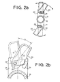
- a rotary cutting device R has a plurality of supporting members 21 (Figure 2a) radially and securely mounted on the rotary shaft 18. As shown in Figures 2a and 2b, on opposite end portions of the supporting members 21, cutters 23 are pivotally supported by pivot bolts 22, respectively. As shown in Figures 5a to 5c, each cutter 23 is made by bending a rectangular metal plate to form a vertical portion 23a and a lateral portion 23b thereby forming a substantially L shape section. A soil cutting edge 23c and a grass cutting edge 23d are formed on opposite sides of a lower portion of the vertical portion 23a and on opposite sides of the lateral portion 23b, edge 23c being for tilling and 23d for mowing.
- a stopper 24 is provided on the supporting member 21 to receive the load exerted on the cutter 23 and to hold it at a tilling position shown by a solid line in Figure 2a, at which the cutter has an angular disposition for tilling, when the rotary shaft 18 and the supporting member 21 are rotated in a tilling direction (downward cutting direction) shown by arrows in solid line.
- the stopper 24 is so positioned to ensure that the cutter 23 is inserted into the soil at a certain entering angle 6( Figure 2b) for efficient inverting and turning of soil.
- a spring plate 25 is secured together with the cutter 23 to the supporting member 21 by the bolt 22 to prevent the deflection of the cutter in the axial direction of the bolt.
- covers 26 and 27 are provided above the front and rear portions of the rotary tilling device 1.
- the cutter 23 For effective grass cutting, it is preferable to mount the cutter 23 on the supporting member 21 so as to form a certain angle between the surface of the ground'and the bottom of the cutter 23.
- the center 0 of a hole 23e for securing the cutter by bolt 22 is deflectd by a mm from a center line L of the cutter 23 towards the soil cutting edge 23c.
- a base portion of the cutter 23 is formed in a semicircle having a radius r about a center P. The center P is positioned on the center line L which passes through the center G of gravity.
- the shift lever 14 is shited so that the shift gear 13 is in engagement with the gear 9. Accordingly, the power of the engine supplied to the input shaft 3 is transmitted to the output shaft 12 through bevel gears 4 and 6, and gears 7 and 9. The power is further transmitted to the rotary shaft 18 through the sprocket wheels 16, 19 and the chain 20. Accordingly, the rotary shaft 18 is rotated at a low speed in the tilling direction.
- the edge 23c of each cutter 23 cuts through the soil to cultivate the surface of the soil.
- the stopper 24 holds the cutter 23 at one side thereof preventing the cutter 23 from further rotating in the counter-tilling direction due to the load exerted on the cutter 23.
- the soil is cultivated by the tilling device.
- the device When the shift lever 14 is shifted to engage the shift gear 13 with the reverse gear 11, the device is in the state for the grass cutting operation.
- the direction of the rotation of the rotary shaft 18 is in reverse to that of the tilling direction, as shown by the arrow in dashed line in Figure 2a. Since reverse gear 11 is smaller than gear 9, the speed of the rotation of the rotary shaft 18 is faster than the tilling operation thereby generating a large centrifugal force. Accordingly, the cutter 23 is disengaged from the stopper 24 and rotates about the bolt 22 and is held at a radial position shown by a chain line of Figure 2b. As a result, grass growing on unplowed land is cut in the same manner as with a conventional rotary flail-type cutter.
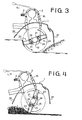
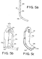
- the periphery of the base portion is disposed at a position more outwardly spaced than the position in the soil cutting operation so that the periphery disengages from the stuck soil. Therefore, friction on the cutter 23 is reduced so that the cutter 23 is reliably rotated to the radial position.
- the rotational speed of the rotary shaft is preferably between 200 to 300 r.p.m. for the tilling operation and about 800 r.p.m. for the grass cutting operation.
Landscapes
- Life Sciences & Earth Sciences (AREA)
- Environmental Sciences (AREA)
- Engineering & Computer Science (AREA)
- Mechanical Engineering (AREA)
- Soil Sciences (AREA)
- Soil Working Implements (AREA)
- Harvester Elements (AREA)
Applications Claiming Priority (2)
| Application Number | Priority Date | Filing Date | Title |
|---|---|---|---|
| JP261958/85 | 1985-11-20 | ||
| JP60261958A JPS62118804A (ja) | 1985-11-20 | 1985-11-20 | 耕うん草刈り装置 |
Publications (2)
| Publication Number | Publication Date |
|---|---|
| EP0224371A2 true EP0224371A2 (fr) | 1987-06-03 |
| EP0224371A3 EP0224371A3 (fr) | 1988-07-20 |
Family
ID=17369014
Family Applications (1)
| Application Number | Title | Priority Date | Filing Date |
|---|---|---|---|
| EP86308996A Withdrawn EP0224371A3 (fr) | 1985-11-20 | 1986-11-18 | Fraise rotative |
Country Status (4)
| Country | Link |
|---|---|
| US (1) | US4778012A (fr) |
| EP (1) | EP0224371A3 (fr) |
| JP (1) | JPS62118804A (fr) |
| AU (1) | AU569668B2 (fr) |
Cited By (8)
| Publication number | Priority date | Publication date | Assignee | Title |
|---|---|---|---|---|
| FR2650937A1 (fr) * | 1989-08-16 | 1991-02-22 | Noremat | Couteau pour machines destinees a la coupe d'herbe et/ou de broussailles |
| EP0443079A3 (en) * | 1990-02-13 | 1995-01-11 | Lundahl Inc Ezra C | Improved crop processor |
| ES2080634A1 (es) * | 1992-02-04 | 1996-02-01 | Univ Catalunya Politecnica | Maquina para arrancar malas hierbas en jardineria. |
| WO1999055138A1 (fr) * | 1998-04-29 | 1999-11-04 | Keith Broomhall | Faucheuse |
| GB2346116A (en) * | 1999-01-30 | 2000-08-02 | John Robert French | Rotary cutter for mine clearance |
| GB2355907A (en) * | 1999-11-02 | 2001-05-09 | J R French Ltd | A blade for digging assembly, and related apparatuses |
| ITPD20100033A1 (it) * | 2010-02-09 | 2011-08-10 | Tierre Srl | Mazza frantumatrice per biotrituratori, trinciatrici e trituratici in generale |
| EP2404491A4 (fr) * | 2009-03-06 | 2014-09-17 | Yanmar Co Ltd | Dent aratoire et rotateur équipé d'une dent aratoire |
Families Citing this family (12)
| Publication number | Priority date | Publication date | Assignee | Title |
|---|---|---|---|---|
| US5121592A (en) * | 1991-06-17 | 1992-06-16 | Jertson John T | Powered sweeper/chopper striker assembly for collecting and chopping materials like leaves from the ground |
| US5651418A (en) * | 1995-04-17 | 1997-07-29 | Jerez; Orlando | Convertible, user-supported, garden cleaning implement for cutting/macerating weeds and like |
| ATE262776T1 (de) * | 2000-02-18 | 2004-04-15 | Pellenc Sa | Bodenbearbeitungsmaschinengerät |
| DE102005023014B4 (de) * | 2005-05-19 | 2008-04-30 | ESM Ennepetaler Schneid- und Mähtechnik GmbH & Co KG | Vorrichtung zum Schneiden von insbesondere hoch wachsendem Schnittgut |
| US20070107401A1 (en) * | 2005-10-28 | 2007-05-17 | Javad Jafarifar | Artistic lawn sculpting machine |
| ES2308922B1 (es) * | 2007-05-17 | 2009-07-24 | Juan Miguel Mayordomo Vicente | Sistema de publicidad estatica para todo tipo de superficies de cesped. |
| JP5709420B2 (ja) * | 2010-07-09 | 2015-04-30 | ハスクバーナ・ゼノア株式会社 | 草刈作業機 |
| IN2014KN00758A (fr) * | 2011-09-05 | 2015-10-02 | Soilkee Pty Ltd | |
| DE102011117770A1 (de) * | 2011-11-07 | 2013-05-08 | Artur Willibald | Fahrzeugvorrichtung |
| US12102022B2 (en) * | 2019-12-23 | 2024-10-01 | Ardisam, Inc. | Dual-direction tiller/cultivator |
| CN113180028A (zh) * | 2021-05-18 | 2021-07-30 | 库来夏·哈孜依 | 一种用于草原毒害草去除的环保型铲除装置 |
| US12376519B2 (en) * | 2022-06-14 | 2025-08-05 | Deere & Company | Quick change blade for a rotating blade assembly of a mower implement |
Family Cites Families (16)
| Publication number | Priority date | Publication date | Assignee | Title |
|---|---|---|---|---|
| DE89854C (fr) * | ||||
| US2656662A (en) * | 1951-01-16 | 1953-10-27 | Walter E Hines | Tractor mounted stalk shredding device |
| US2751737A (en) * | 1953-09-25 | 1956-06-26 | Henderson B Herod | Disc type mowing apparatus having pivoted blades |
| US2990667A (en) * | 1959-08-11 | 1961-07-04 | Sperry Rand Corp | Forage harvester |
| US3028919A (en) * | 1960-11-04 | 1962-04-10 | Smith Alexander | Mower and hoe |
| AU4781464A (en) * | 1965-08-05 | 1967-02-09 | Rover Mowers Pty. Ltd | Improvements in and relating to rotary mowers tillers and similar machines |
| NL6614376A (fr) * | 1966-10-13 | 1968-04-16 | ||
| FR2242149B2 (fr) * | 1973-09-05 | 1977-05-13 | Carre Francois | |
| DE2551857C3 (de) * | 1974-04-18 | 1980-11-13 | Josef Willibald, Maschinenfabrik, 7771 Frickingen | Landwirtschaftliches Bodenbearbeitungsgerät |
| US4492271A (en) * | 1982-07-12 | 1985-01-08 | Brinly-Hardy Co., Inc. | Tine tiller with tines and wheels each rotatable in either direction |
| AU1779283A (en) * | 1982-07-28 | 1984-02-23 | Byrd George Malcolm | Improvements relating to rotary agitators |
| JPS5985203A (ja) * | 1982-11-06 | 1984-05-17 | 株式会社クボタ | 正逆転両用形耕耘爪の取付け構造 |
| US4519459A (en) * | 1983-03-31 | 1985-05-28 | Magna American Corporation | Power drive rear tine tiller with reversing gear transmission for the tines |
| JPS6037901A (ja) * | 1983-08-11 | 1985-02-27 | 株式会社クボタ | 正逆転ロ−タリ |
| US4611669A (en) * | 1984-03-29 | 1986-09-16 | Mtd Products Inc. | Tine assembly |
| US4805704A (en) * | 1985-10-12 | 1989-02-21 | Kobashi Kogyo Co., Ltd. | Rotary tilling device |
-
1985
- 1985-11-20 JP JP60261958A patent/JPS62118804A/ja active Granted
-
1986
- 1986-11-17 US US06/931,757 patent/US4778012A/en not_active Expired - Lifetime
- 1986-11-18 AU AU65398/86A patent/AU569668B2/en not_active Ceased
- 1986-11-18 EP EP86308996A patent/EP0224371A3/fr not_active Withdrawn
Cited By (10)
| Publication number | Priority date | Publication date | Assignee | Title |
|---|---|---|---|---|
| FR2650937A1 (fr) * | 1989-08-16 | 1991-02-22 | Noremat | Couteau pour machines destinees a la coupe d'herbe et/ou de broussailles |
| EP0443079A3 (en) * | 1990-02-13 | 1995-01-11 | Lundahl Inc Ezra C | Improved crop processor |
| EP0784918A3 (fr) * | 1990-02-13 | 1997-10-15 | Lundahl Inc Ezra C | Dispositif de traitement de récolte à vis sans fin coupante |
| ES2080634A1 (es) * | 1992-02-04 | 1996-02-01 | Univ Catalunya Politecnica | Maquina para arrancar malas hierbas en jardineria. |
| WO1999055138A1 (fr) * | 1998-04-29 | 1999-11-04 | Keith Broomhall | Faucheuse |
| GB2346116A (en) * | 1999-01-30 | 2000-08-02 | John Robert French | Rotary cutter for mine clearance |
| US6481326B2 (en) | 1999-01-30 | 2002-11-19 | J R French Limited | Cutting assembly and related apparatuses |
| GB2355907A (en) * | 1999-11-02 | 2001-05-09 | J R French Ltd | A blade for digging assembly, and related apparatuses |
| EP2404491A4 (fr) * | 2009-03-06 | 2014-09-17 | Yanmar Co Ltd | Dent aratoire et rotateur équipé d'une dent aratoire |
| ITPD20100033A1 (it) * | 2010-02-09 | 2011-08-10 | Tierre Srl | Mazza frantumatrice per biotrituratori, trinciatrici e trituratici in generale |
Also Published As
| Publication number | Publication date |
|---|---|
| JPS62118804A (ja) | 1987-05-30 |
| US4778012A (en) | 1988-10-18 |
| AU6539886A (en) | 1987-05-28 |
| AU569668B2 (en) | 1988-02-11 |
| EP0224371A3 (fr) | 1988-07-20 |
| JPH0458284B2 (fr) | 1992-09-17 |
Similar Documents
| Publication | Publication Date | Title |
|---|---|---|
| US4778012A (en) | Rotary tilling and grass cutting device | |
| US4805704A (en) | Rotary tilling device | |
| US4492271A (en) | Tine tiller with tines and wheels each rotatable in either direction | |
| US3442335A (en) | Soil tilling device | |
| US3128729A (en) | All-purpose farm machine | |
| CA1229258A (fr) | Machine aratoire a transmission perfectionnee | |
| US4804047A (en) | Rotary mower and tilling device | |
| US4641713A (en) | Soil cultivating machines | |
| US4492273A (en) | Rotary surface cultivator | |
| US4615395A (en) | Reversible rotary cultivating apparatus | |
| US4270614A (en) | Stone rake and ground conditioning machine | |
| KR20230031055A (ko) | 주행방향과 평행한 제초날 회전축을 가진 중경 제초기 | |
| JP3279931B2 (ja) | ロータリ耕耘爪 | |
| JPH0458285B2 (fr) | ||
| JP2000125604A (ja) | 縦軸ロータリ式耕耘機 | |
| GB2065195A (en) | Improvements in or relating to trench-digging machines | |
| JPH0646882B2 (ja) | 耕うん草刈り装置 | |
| JP3922856B2 (ja) | 刈取用作業機 | |
| JPH0458286B2 (fr) | ||
| JP3286438B2 (ja) | ロ−タリ耕耘装置の爪軸駆動装置 | |
| JP2532784Y2 (ja) | 牽引型対地作業機の駆動装置 | |
| JPH0525376Y2 (fr) | ||
| KR200260547Y1 (ko) | 농업관리기 취부용 예초기 | |
| KR200329294Y1 (ko) | 좌/우 각도 조절 가능한 제초기 | |
| KR19990021876U (ko) | 예초기의동력을이용하는소형농기계 |
Legal Events
| Date | Code | Title | Description |
|---|---|---|---|
| PUAI | Public reference made under article 153(3) epc to a published international application that has entered the european phase |
Free format text: ORIGINAL CODE: 0009012 |
|
| 17P | Request for examination filed |
Effective date: 19861128 |
|
| AK | Designated contracting states |
Kind code of ref document: A2 Designated state(s): AT CH DE ES FR GB IT LI |
|
| PUAL | Search report despatched |
Free format text: ORIGINAL CODE: 0009013 |
|
| AK | Designated contracting states |
Kind code of ref document: A3 Designated state(s): AT CH DE ES FR GB IT LI |
|
| 17Q | First examination report despatched |
Effective date: 19900924 |
|
| STAA | Information on the status of an ep patent application or granted ep patent |
Free format text: STATUS: THE APPLICATION IS DEEMED TO BE WITHDRAWN |
|
| 18D | Application deemed to be withdrawn |
Effective date: 19910205 |
|
| RIN1 | Information on inventor provided before grant (corrected) |
Inventor name: KOBASHI, ICHIROC/O KOBASHI KOGYO CO., LTD. Inventor name: TOUKI, YOSHIOC/O KOBASHI KOGYO CO., LTD. Inventor name: KOBASHI, TERUHISAC/O KOBASHI KOGYO CO., LTD. Inventor name: KOBIKI, YASUHIROC/O KOBASHI KOGYO CO., LTD. |