EP0224374A2 - Assemblage pour plafond grillagé - Google Patents
Assemblage pour plafond grillagé Download PDFInfo
- Publication number
- EP0224374A2 EP0224374A2 EP86309046A EP86309046A EP0224374A2 EP 0224374 A2 EP0224374 A2 EP 0224374A2 EP 86309046 A EP86309046 A EP 86309046A EP 86309046 A EP86309046 A EP 86309046A EP 0224374 A2 EP0224374 A2 EP 0224374A2
- Authority
- EP
- European Patent Office
- Prior art keywords
- panel
- clip
- ceiling assembly
- screen
- screen ceiling
- Prior art date
- Legal status (The legal status is an assumption and is not a legal conclusion. Google has not performed a legal analysis and makes no representation as to the accuracy of the status listed.)
- Granted
Links
Images


Classifications
-
- E—FIXED CONSTRUCTIONS
- E04—BUILDING
- E04B—GENERAL BUILDING CONSTRUCTIONS; WALLS, e.g. PARTITIONS; ROOFS; FLOORS; CEILINGS; INSULATION OR OTHER PROTECTION OF BUILDINGS
- E04B9/00—Ceilings; Construction of ceilings, e.g. false ceilings; Ceiling construction with regard to insulation
- E04B9/22—Connection of slabs, panels, sheets or the like to the supporting construction
- E04B9/24—Connection of slabs, panels, sheets or the like to the supporting construction with the slabs, panels, sheets or the like positioned on the upperside of, or held against the underside of the horizontal flanges of the supporting construction or accessory means connected thereto
- E04B9/26—Connection of slabs, panels, sheets or the like to the supporting construction with the slabs, panels, sheets or the like positioned on the upperside of, or held against the underside of the horizontal flanges of the supporting construction or accessory means connected thereto by means of snap action of elastically deformable elements held against the underside of the supporting construction
-
- E—FIXED CONSTRUCTIONS
- E04—BUILDING
- E04B—GENERAL BUILDING CONSTRUCTIONS; WALLS, e.g. PARTITIONS; ROOFS; FLOORS; CEILINGS; INSULATION OR OTHER PROTECTION OF BUILDINGS
- E04B9/00—Ceilings; Construction of ceilings, e.g. false ceilings; Ceiling construction with regard to insulation
- E04B9/34—Grid-like or open-work ceilings, e.g. lattice type box-like modules, acoustic baffles
- E04B9/36—Grid-like or open-work ceilings, e.g. lattice type box-like modules, acoustic baffles consisting of parallel slats
- E04B9/366—Grid-like or open-work ceilings, e.g. lattice type box-like modules, acoustic baffles consisting of parallel slats the principal plane of the slats being vertical
Definitions
- This invention relates to a screen ceiling assembly and components for use therein and in particular clip elements which are used for interconnection of adjoining parts of the screen ceiling assembly.
- Hitherto conventional screen ceiling assemblies have included a plurality of vertically oriented screens or panels attached in spaced relationship to a plurality of panel carrier rails or stringers.
- the carrier rails were parallel to each other and arranged transversely to the plurality of panels.
- the carrier rails were usually suspended by cables or rods which were attached to a supporting roof structure.
- each clip included an upper portion received in slots in a carrier rail and a lower spring clip portion gripping an upper marginal edge of a panel.
- Each carrier rail or stringer was a downwardly facing channel member having paired opposed slots formed therein.
- the upper portion of each clip included a pair of opposed tabs respectively received in an opposed pair of such slots and shaped so as to be readily insertable but to be effectively locked in position after insertion in the carrier rail slots.
- the clips could also be bent intermediate their upper and lower portions for orienting the major surface planes of the panels at a desired angle to the carrier rails so that the panel major surface planes are vertically oriented when the carrier rails are pitched at an angle to horizontal as over a stairway.
- Each of the conventional screen ceiling assemblies were disadvantageous in that the panels were fixed in position relative to their associated carrier rails and thus although rotation or pivotal movement of each panel was possible about a transverse axis thereof (i.e. normal to an associated carrier rail) at least insofar as the first type of assembly described above was concerned it was usually not possible to pivot the panel about a longitudinal axis thereof (i.e. parallel to an associated carrier rail).
- This meant that conventional screen ceiling assemblies of the types described above were usually not versatile in operation or application because they were usually only able to be suspended from the carrier rails in a substantially vertical plane. It was also usually the case that the spacings between adjacent panels were substantially equal and unequal spacings were normally not envisaged.
- a screen ceiling assembly comprising a plurality of spaced carrier members, connectable to a support structure, to form a common plane through said carrier members; a multiplicity of spaced elongate ceiling panels each having its own longitudinal axis, said panels being positioned at an angle to said common plane; clip means interconnecting each ceiling panel with at least one of said carrier members; and a pivotal connection associated with each clip means, effective to allow each ceiling panel to be pivoted about an axis parallel to its longitudinal axis, whereby each panel may be disposed at a desired angle or angles with respect to said common plane.
- each panel in the desired angled manner. It is possible, according to this construction, to have each panel angled bodily in the same plane, or to have different parts of the same panel disposed at different angles, thereby providing a twisted configuration to the panel.
- each clip means may comprise a panel engagement portion and a separate head portion, the head portion being attached to the carrier member, the pivotal connection being provided between the panel engagement portion and the separate head portion.
- the separate head portion can be rigidly fixed to the carrier and the pivotal disposition of the panels can be effected by the pivotal connection within each clip means.
- Advantageously retaining means are provided to retain each panel in the desired angled position and this may take many forms.
- they may comprise abutting elements on each clip means and its associated carrier, a detent element resiliently engagable in one or more recesses, an interengagable plug and socket arrangement or a retaining means which allows the pivoting at the pivotal connection to be effected incrementally, so that at least a part of each clip means may be retained in any one of number of different incremental angular positions relative to its associated carrier member.
- the carriers may be of any suitable type and thus comprise a carrier rail suitably of channel cross section or a tubular rail or even a rod or elongate sheet member.
- a carrier rail of channel cross section is preferred.
- the ceiling panels also may be of any suitable type and thus may comprise a plate-like member having a body portion optionally provided with one or more reinforcing ribs or grooves and one or more peripheral longitudinal flanges which may be hooked or oriented at right angles to the body portion.
- the ceiling panel includes an upper flange of hooked or V or C shape and a lower flange of similar shape.
- the clip means is unitary and thus comprise a clip element and include an upper part or head portion which is attached to the carrier by suitable attachment means and a lower part which may rigidly secure the ceiling panel but more preferably allows movement of the ceiling panel about a transverse axis.
- the attachment means may have associated therewith pivot means whereby the clip element and attached panel may be pivoted to the desired position.
- the attachment means may also have associated therewith retaining means to retain the clip element and atached panel in the desired position.
- the clip element may include a head portion possessing a retaining aperture for an appropriate fastener and a pair of legs depending therefrom for grasping an associated panel.
- one leg is longer than the other so that the free ends of each leg may have vertically displaced or vertically spaced bearing locations upon mating engagement with the panel.
- each leg which in a top portion thereof may be provided with one or more bearing parts which may mate with an associated flange or flanges of a V top flange of the ceiling panel.
- pivot means and retaining means may be separate from each other and in this arrangement the clip may pivot about a pivot pin and be retained in a suitable position such as in a vertical plane or a plane offset to the vertical by retaining means such as a screw clamp extending through spaced portions of the clip element or by a plug and socket engagement between the clip and the carrier rail.
- the separate retaining means may be such as to enable the clip element to be pivoted through an angle offset to the vertical by increments such as by angular increments of 5 degrees.
- increments such as by angular increments of 5 degrees.
- FIG. l there is illustrated a head portion ll with an attachment or retaining aperture l2 hollow recesses l3 to reduce the weight of the clip and save on use of material, webs l4 and l5, external flanges l6 and l7, legs l8 and l9 and a slot 20 between legs l8 and l9. Also shown are bearing pads or feet 2l and 22 and it will be noted that foot 22 is longer than foot 2l as shown in Figure 4 so as to bear against an associated panel 23 at spaced locations. This feature is useful in that it facilitates pivotal movement of panel 23 relative to clip l0 about a transverse axis and also allows easy insertion of panel 23 into slot 20 through the slot entrance 24.
- FIG. 4 Also shown is a bearing face 25 of slot 20 which may bear against an adjacent face of a flange 27 of panel 23 as shown in Figure 4.
- the three point engagement between panel 23 and clip l0 shown in Figure 4 enables the panel 23 to be securely retained in an associated clip l0.
- FIG 2 there is shown a carrier rail 29 having opposed side flanges 30, web 3l and opposed bottom flanges 32. Also shown is rivet 33 extending through aligned apertures 34 in flanges 30.
- the rivet as shown in Figure 3 has a deformed end portion 35 after insertion in apertures 34 so as to retain head portion ll of clip l0 securely in channel 36 of carrier rail 29.
- the rivet also has head 37.
- Figure 4 shows panel 23 having a top V shaped part 4l having adjacent flanges 27 and 28, body portion 42 having reinforcing grooves 43 and bottom part 44 comprising oblique flange 45 and horizontal flange 46 with lip 47.
- carrier rail 29 is shown schematically and it will be appreciated as stated previously that rail 29 may comprise an elongate sheet or plate 29A if desired. However preferably rail 29 is of the channel form shown in Figure 2 and thus numeral 29A may correspond to one flange 30.
- clip l0 also shown schematically is freely pivoted on pivot pin 48 through washer 49 and is also provided with outwardly extending abutments 5l and 52 on each side thereof so as to engage with the underside 53 of member 29A.
- Figure 6 shows spaced pivot lugs or pins 48 and a screw clamp 54 which may be inserted in a mating socket in clip l0 so as to urge together branch portions 55 of bifurcated end 56 of clip l0.
- FIG. 7 there is shown anchor lug 57 engaging in a corresponding socket 58 of clip l0 to retain clip l0 in a desired position offset to the vertical as shown.
- FIG 9 there is shown a retaining rib 6l of plate 29A which may selectively engage in a single groove of a plurality of grooves 62 of clip l0 to again provide an alternative embodiment to that shown in Figure 8 concerning obtaining pivotal angular increments of movement of clip l0 relative to plate 29A.
- FIG l0 it is shown how panel 23 is pivoted about a transverse axis relative to clips l0 as may be required.
- the carrier rails 29 are of varying height thus providing angled panels 23 as well as vertically oriented panels 23.
- Various other arrangements of angled panels are also possible which may be achieved by suspending carrier rails at varying heights relative to the floor.
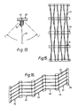
- FIGs ll and l2 there are shown various possible arrangements of horizontal carrier rails, vertical panels, angled panels and angled carrier rails.
- angled carrier rails 29 are located intermediate horizontal carrier rails 29 and each panel 23 is oriented transverse to carrier rails 29 as shown.
- Figure ll shows vertically oriented panels 23, and in Figure l2 all panels 23 are angled as shown. It is also possible for panels 23 to be inclined to the vertical at varying angles if such is required.
- Figure l3 shows one example of the range of pivotal movement possible for panel 23 about longitudinal axis 40 relative to carrier rail 29 wherein the two extremes of pivotal movement are shown in phantom and vertical position in full outline.
- FIGs l4 and l5 there is shown an embodiment wherein selective orientation of adjacent panels 23 about longitudinal axis 40 may provide a resulting arrangement where panels 23 may be arranged in a spiral or helical configuration or curved configuration.
- a single panel 23 has a rear end portion oriented at a different angle from a front end portion, as shown, so that the panel is twisted about its mid-region.
- a curved arrangement may be obtained as shown by way of example in Figure l5, which illustrates one particular curved arrangement whch may be obtained by the present invention.
- Figure l6 there is also shown a particular arrangement which is based on a straight line or planar configuration.
- adjacent rows 63, 64, 65, 66 and 67 may be parallel or angled to each other as shown in Figure l6 with the panels 23 or one row 66 offset to one or more of the other rows.
- the invention also includes within its scope the aforementioned clip element per se .
Landscapes
- Engineering & Computer Science (AREA)
- Architecture (AREA)
- Physics & Mathematics (AREA)
- Electromagnetism (AREA)
- Civil Engineering (AREA)
- Structural Engineering (AREA)
- Connection Of Plates (AREA)
- Curtains And Furnishings For Windows Or Doors (AREA)
- Mutual Connection Of Rods And Tubes (AREA)
- Vehicle Interior And Exterior Ornaments, Soundproofing, And Insulation (AREA)
- Seats For Vehicles (AREA)
- Residential Or Office Buildings (AREA)
Applications Claiming Priority (2)
| Application Number | Priority Date | Filing Date | Title |
|---|---|---|---|
| AU50203/85A AU570349B2 (en) | 1985-11-20 | 1985-11-20 | Screen ceiling assembly |
| AU50203/85 | 1985-11-20 |
Publications (3)
| Publication Number | Publication Date |
|---|---|
| EP0224374A2 true EP0224374A2 (fr) | 1987-06-03 |
| EP0224374A3 EP0224374A3 (en) | 1987-12-02 |
| EP0224374B1 EP0224374B1 (fr) | 1990-09-05 |
Family
ID=3736695
Family Applications (1)
| Application Number | Title | Priority Date | Filing Date |
|---|---|---|---|
| EP86309046A Expired - Lifetime EP0224374B1 (fr) | 1985-11-20 | 1986-11-19 | Assemblage pour plafond grillagé |
Country Status (12)
| Country | Link |
|---|---|
| US (1) | US4720954A (fr) |
| EP (1) | EP0224374B1 (fr) |
| JP (1) | JPH0699980B2 (fr) |
| AU (1) | AU570349B2 (fr) |
| BE (1) | BE905782A (fr) |
| CH (1) | CH671424A5 (fr) |
| DE (1) | DE3673958D1 (fr) |
| ES (1) | ES2018161B3 (fr) |
| FR (1) | FR2590303B1 (fr) |
| GB (1) | GB2183270B (fr) |
| NZ (1) | NZ218329A (fr) |
| ZA (1) | ZA868802B (fr) |
Cited By (1)
| Publication number | Priority date | Publication date | Assignee | Title |
|---|---|---|---|---|
| WO1993016246A1 (fr) * | 1992-02-15 | 1993-08-19 | Rockwool Systeme Gmbh | Dispositif pour insonoriser des pieces |
Families Citing this family (5)
| Publication number | Priority date | Publication date | Assignee | Title |
|---|---|---|---|---|
| USD319385S (en) | 1988-08-01 | 1991-08-27 | Paul Harold J | Hanger clamp for ceiling construction |
| US5467266A (en) * | 1991-09-03 | 1995-11-14 | Lutron Electronics Co., Inc. | Motor-operated window cover |
| US5241799A (en) * | 1991-12-10 | 1993-09-07 | Chicago Metallic Corporation | Open cell lay-in panel |
| GB2545789B (en) * | 2015-11-02 | 2020-04-01 | Autex Industries Ltd | Panel fixing assembly |
| EP4433667A4 (fr) * | 2021-11-16 | 2025-11-05 | Certainteed Ceilings Corp | Support pour panneaux de plafond inclinés et système de panneaux de plafond |
Family Cites Families (21)
| Publication number | Priority date | Publication date | Assignee | Title |
|---|---|---|---|---|
| US2437825A (en) * | 1946-04-19 | 1948-03-16 | Kohn Max | Lamp shade |
| US2552982A (en) * | 1947-08-01 | 1951-05-15 | Air Factors | Adjustable grille construction |
| US2585089A (en) * | 1949-11-16 | 1952-02-12 | Caldwell Ford Weddington | Resilient clamp |
| US2952049A (en) * | 1957-08-23 | 1960-09-13 | Arrow Metal Products Corp Inc | Remote controlled adjustable awning |
| FR1286348A (fr) * | 1960-08-15 | 1962-03-02 | Koller Metallbau Ag | Plafond pour constructions |
| US3254451A (en) * | 1964-04-20 | 1966-06-07 | Russell M Wills | Adjustable louver structure |
| GB1044478A (en) * | 1964-07-27 | 1966-09-28 | Carter Engineering Company Tam | Improvements relating to screens |
| FR1464883A (fr) * | 1965-11-26 | 1967-01-06 | Faux plafond diffusant orientable | |
| DE1759845C3 (de) * | 1968-06-14 | 1974-02-14 | Fa. Hunter Douglas, Rotterdam (Niederlande) | Lamellenhalter für eine Wand- oder Deckenverkleidung aus an Tragschienen angeordneten Lamellen |
| GB1323055A (en) * | 1969-09-12 | 1973-07-11 | Burgess Products Co Ltd | False ceiling system |
| US3755988A (en) * | 1971-11-08 | 1973-09-04 | Hunter Douglas International | Panel assembly |
| US3774024A (en) * | 1971-12-20 | 1973-11-20 | C Deaton | Illuminator grid |
| US3981116A (en) * | 1973-06-14 | 1976-09-21 | Alcan Aluminum Corporation | Sheathing system for building structures |
| US3911638A (en) * | 1974-04-22 | 1975-10-14 | Alcan Aluminum Corp | Vertical ceiling assembly and clip elements therefor |
| DE2826654C2 (de) * | 1978-06-19 | 1985-10-31 | König, Willi, 4700 Hamm | Unterdecke |
| US4222094A (en) * | 1978-10-30 | 1980-09-09 | William Wolar | Means including a light distribution louver for the protection of lighting fixtures |
| GB2097439B (en) * | 1981-04-24 | 1984-10-10 | Hunter Douglas Ind Bv | Adjustable suspended ceiling |
| FR2523622A1 (fr) * | 1982-03-18 | 1983-09-23 | Perradin Guy | Procede pour la realisation de faux-plafonds et faux-plafonds obtenus |
| US4448005A (en) * | 1982-09-27 | 1984-05-15 | Hollywood Accessories | Interior automotive sunshade with ring hinges |
| DE3337436C2 (de) * | 1982-10-21 | 1985-07-04 | Alu-System AG, Wädenswil | Lamellen-Sonnenschutz |
| GB2168090B (en) * | 1984-12-06 | 1988-02-24 | Hunter Douglas Ind Bv | Suspended ceiling |
-
1985
- 1985-11-20 AU AU50203/85A patent/AU570349B2/en not_active Ceased
-
1986
- 1986-11-14 US US06/930,832 patent/US4720954A/en not_active Expired - Fee Related
- 1986-11-17 CH CH4587/86A patent/CH671424A5/fr not_active IP Right Cessation
- 1986-11-19 EP EP86309046A patent/EP0224374B1/fr not_active Expired - Lifetime
- 1986-11-19 ES ES86309046T patent/ES2018161B3/es not_active Expired - Lifetime
- 1986-11-19 GB GB08627609A patent/GB2183270B/en not_active Expired
- 1986-11-19 NZ NZ218329A patent/NZ218329A/xx unknown
- 1986-11-19 BE BE0/217433A patent/BE905782A/fr not_active IP Right Cessation
- 1986-11-19 DE DE8686309046T patent/DE3673958D1/de not_active Expired - Fee Related
- 1986-11-19 FR FR868616093A patent/FR2590303B1/fr not_active Expired - Fee Related
- 1986-11-20 ZA ZA868802A patent/ZA868802B/xx unknown
- 1986-11-20 JP JP61277761A patent/JPH0699980B2/ja not_active Expired - Lifetime
Cited By (1)
| Publication number | Priority date | Publication date | Assignee | Title |
|---|---|---|---|---|
| WO1993016246A1 (fr) * | 1992-02-15 | 1993-08-19 | Rockwool Systeme Gmbh | Dispositif pour insonoriser des pieces |
Also Published As
| Publication number | Publication date |
|---|---|
| FR2590303B1 (fr) | 1992-04-17 |
| EP0224374A3 (en) | 1987-12-02 |
| GB2183270A (en) | 1987-06-03 |
| GB2183270B (en) | 1988-12-29 |
| ZA868802B (en) | 1987-07-29 |
| NZ218329A (en) | 1989-04-26 |
| JPH0699980B2 (ja) | 1994-12-12 |
| AU570349B2 (en) | 1988-03-10 |
| EP0224374B1 (fr) | 1990-09-05 |
| JPS62153445A (ja) | 1987-07-08 |
| BE905782A (fr) | 1987-05-19 |
| AU5020385A (en) | 1987-05-28 |
| DE3673958D1 (de) | 1990-10-11 |
| US4720954A (en) | 1988-01-26 |
| GB8627609D0 (en) | 1986-12-17 |
| FR2590303A1 (fr) | 1987-05-22 |
| CH671424A5 (fr) | 1989-08-31 |
| ES2018161B3 (es) | 1991-04-01 |
Similar Documents
| Publication | Publication Date | Title |
|---|---|---|
| CA1137730A (fr) | Systeme de suspension de cloison amovible | |
| US4811539A (en) | Wall framing system | |
| CA1038811A (fr) | Etagere et montants d'angles | |
| US4557086A (en) | Grain bin floor support system | |
| US5363622A (en) | Fire-rated drywall suspension system | |
| US6179136B1 (en) | Shelf mounting system | |
| US4787767A (en) | Stud clip for the top rail of a partition | |
| US4723749A (en) | Channel clip | |
| US4982933A (en) | Fence connector clip and assembly | |
| WO2002090705A2 (fr) | Connecteur d'armature sismique | |
| US3911638A (en) | Vertical ceiling assembly and clip elements therefor | |
| EP0198982A2 (fr) | Faux plafond à résilles | |
| CA2009596A1 (fr) | Dispositif de fixation pour assujettir un couronnement de panneau | |
| US4051638A (en) | Removable enclosure for a swimming pool or the like | |
| US3232021A (en) | Ceiling structure | |
| US7261213B2 (en) | Closet partition system | |
| EP0224374B1 (fr) | Assemblage pour plafond grillagé | |
| US4781005A (en) | Ceiling panel carrier adapter member | |
| US5551792A (en) | Connector | |
| US4715741A (en) | Clip for coupling shelf assemblies | |
| JPS63138038A (ja) | デツキプレ−トに於けるハンガ−構造 | |
| AU739513B2 (en) | Adjustable two-piece clip for mounting objects on a wall stud | |
| US4015811A (en) | Support for a vaulted ceiling module - II | |
| EP0795657B1 (fr) | Système de montage pour plafonds suspendus | |
| US11118359B2 (en) | Construction system for wall cladding |
Legal Events
| Date | Code | Title | Description |
|---|---|---|---|
| PUAI | Public reference made under article 153(3) epc to a published international application that has entered the european phase |
Free format text: ORIGINAL CODE: 0009012 |
|
| AK | Designated contracting states |
Kind code of ref document: A2 Designated state(s): DE ES IT NL SE |
|
| PUAL | Search report despatched |
Free format text: ORIGINAL CODE: 0009013 |
|
| AK | Designated contracting states |
Kind code of ref document: A3 Designated state(s): DE ES IT NL SE |
|
| 17P | Request for examination filed |
Effective date: 19880111 |
|
| 17Q | First examination report despatched |
Effective date: 19890908 |
|
| GRAA | (expected) grant |
Free format text: ORIGINAL CODE: 0009210 |
|
| AK | Designated contracting states |
Kind code of ref document: B1 Designated state(s): DE ES IT NL SE |
|
| REF | Corresponds to: |
Ref document number: 3673958 Country of ref document: DE Date of ref document: 19901011 |
|
| ITF | It: translation for a ep patent filed | ||
| PLBE | No opposition filed within time limit |
Free format text: ORIGINAL CODE: 0009261 |
|
| STAA | Information on the status of an ep patent application or granted ep patent |
Free format text: STATUS: NO OPPOSITION FILED WITHIN TIME LIMIT |
|
| 26N | No opposition filed | ||
| ITTA | It: last paid annual fee | ||
| PGFP | Annual fee paid to national office [announced via postgrant information from national office to epo] |
Ref country code: SE Payment date: 19921104 Year of fee payment: 7 |
|
| PGFP | Annual fee paid to national office [announced via postgrant information from national office to epo] |
Ref country code: NL Payment date: 19921130 Year of fee payment: 7 Ref country code: ES Payment date: 19921130 Year of fee payment: 7 |
|
| PGFP | Annual fee paid to national office [announced via postgrant information from national office to epo] |
Ref country code: DE Payment date: 19921212 Year of fee payment: 7 |
|
| PG25 | Lapsed in a contracting state [announced via postgrant information from national office to epo] |
Ref country code: SE Effective date: 19931120 Ref country code: ES Free format text: LAPSE BECAUSE OF NON-PAYMENT OF DUE FEES Effective date: 19931120 |
|
| PG25 | Lapsed in a contracting state [announced via postgrant information from national office to epo] |
Ref country code: NL Effective date: 19940601 |
|
| NLV4 | Nl: lapsed or anulled due to non-payment of the annual fee | ||
| PG25 | Lapsed in a contracting state [announced via postgrant information from national office to epo] |
Ref country code: DE Effective date: 19940802 |
|
| EUG | Se: european patent has lapsed |
Ref document number: 86309046.0 Effective date: 19940610 |
|
| REG | Reference to a national code |
Ref country code: ES Ref legal event code: FD2A Effective date: 19941214 |
|
| PG25 | Lapsed in a contracting state [announced via postgrant information from national office to epo] |
Ref country code: IT Free format text: LAPSE BECAUSE OF NON-PAYMENT OF DUE FEES;WARNING: LAPSES OF ITALIAN PATENTS WITH EFFECTIVE DATE BEFORE 2007 MAY HAVE OCCURRED AT ANY TIME BEFORE 2007. THE CORRECT EFFECTIVE DATE MAY BE DIFFERENT FROM THE ONE RECORDED. Effective date: 20051119 |