EP0795657B1 - Système de montage pour plafonds suspendus - Google Patents
Système de montage pour plafonds suspendus Download PDFInfo
- Publication number
- EP0795657B1 EP0795657B1 EP19970301649 EP97301649A EP0795657B1 EP 0795657 B1 EP0795657 B1 EP 0795657B1 EP 19970301649 EP19970301649 EP 19970301649 EP 97301649 A EP97301649 A EP 97301649A EP 0795657 B1 EP0795657 B1 EP 0795657B1
- Authority
- EP
- European Patent Office
- Prior art keywords
- bracket
- carrier
- profile
- mounting
- ceiling
- Prior art date
- Legal status (The legal status is an assumption and is not a legal conclusion. Google has not performed a legal analysis and makes no representation as to the accuracy of the status listed.)
- Expired - Lifetime
Links
- 238000003780 insertion Methods 0.000 claims description 2
- 230000037431 insertion Effects 0.000 claims description 2
- 230000001419 dependent effect Effects 0.000 claims 1
- 230000000063 preceeding effect Effects 0.000 claims 1
- 239000000969 carrier Substances 0.000 description 19
- 238000005553 drilling Methods 0.000 description 3
- 238000000034 method Methods 0.000 description 3
- 230000000694 effects Effects 0.000 description 2
- 239000000725 suspension Substances 0.000 description 2
- 230000001154 acute effect Effects 0.000 description 1
- 238000010276 construction Methods 0.000 description 1
- 238000009434 installation Methods 0.000 description 1
- 239000002184 metal Substances 0.000 description 1
- 238000012986 modification Methods 0.000 description 1
- 230000004048 modification Effects 0.000 description 1
- 239000004575 stone Substances 0.000 description 1
- 210000002105 tongue Anatomy 0.000 description 1
Images


Classifications
-
- E—FIXED CONSTRUCTIONS
- E04—BUILDING
- E04B—GENERAL BUILDING CONSTRUCTIONS; WALLS, e.g. PARTITIONS; ROOFS; FLOORS; CEILINGS; INSULATION OR OTHER PROTECTION OF BUILDINGS
- E04B9/00—Ceilings; Construction of ceilings, e.g. false ceilings; Ceiling construction with regard to insulation
- E04B9/30—Ceilings; Construction of ceilings, e.g. false ceilings; Ceiling construction with regard to insulation characterised by edge details of the ceiling; e.g. securing to an adjacent wall
Definitions
- the present invention relates to a ceiling mounting system which can be used for mounting a ceiling suspended from a number of longitudinal carriers which span a room. Typically this is a false ceiling made up of ceiling panels.
- a mounting system of this general type is shown in document NL 71/07,694.
- a number of longitudinal room carriers span the room area and are connected at their ends to perimeter support members which are fixed at a constant height around the entire perimeter of the room.
- the spans of the longitudinal room carriers are supported in the middle by hanger arrangements which are themselves suspended from the actual ceiling of the room.
- the perimeter support members are secured to the walls by suitably placed screws. The false ceiling is then suspended from the longitudinal room carriers and perimeter support members.
- US-A-4,715,161 describes a semi-adjustable system which uses wall brackets having barbs to catch a top edge of a wall profile at one of several positions.
- the brackets also have means to support and engage cross spars, but not at adjustable heights.
- hanger arrangements must, themselves, be accurately placed so that they can support room carriers immediately beneath them. If a hanger is misplaced, it must be repositioned. Sometimes it simply is not possible to put a hanger in its ideal position.
- a mounting system for supporting a ceiling comprising:
- the present invention also contemplates a ceiling support system comprising the above mounting system and a splicing bracket for splicing together the ends of two carrier members of a room carrier, the splicing bracket comprising:
- the present invention further contemplates a ceiling hanging system comprising the above mounting system or the above support system and a hanger arrangement for supporting a room carrier between the carrier's two ends, the hanger arrangement comprising:
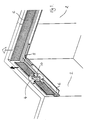
- mounting means comprising a plurality of wall brackets 4 are secured to a wall 2 at spaced intervals.
- the wall brackets in turn support perimeter profiles, in this case wall profiles 6, which are used for supporting longitudinal room carriers or other room carriers.
- corner connectors 8 can be used to connect the wall profiles 6 at the corners.
- the wall profile 6 has a vertically extending toothed portion 20 with a series of downward pointing ratchet teeth 24 along its length.
- a carrier support portion in this case horizontally extending elongate ledge 22 is provided to support the ends of longitudinal room carriers.
- a further portion extends downwardly from the base of the toothed portion 20 as an edge cover support portion 26, the top of which has an edge cover retaining portion 28.
- the wall bracket 4 includes a detent portion, in this case a locking spring clip 10.
- This has an upwardly angled detent or pawl 30 for catching on the ratchet teeth 24 of the toothed portion 20 of the wall profile 6.
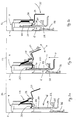
- a handle 32 of the spring clip 10 is in the position shown in Figure 2a then the pawl 30 is able to pivot back and forth. This is as indicated by arrow 31 in Figure 2b where, as the wall profile 6 is pushed upwards, the sloped surfaces of its teeth 24 push the sloped surface of the pawl 30 away. In this fashion the wall profile 6 is allowed to move upwards as indicated by arrow 21.
- the spring clip 10 is provided with a locking detent 34 which is able to clip onto a portion of the wall bracket 4 in order to hold the spring clip 10 and the pawl 30 in a locking position. Then the wall profile 6 is prevented from moving up or down.
- one or more wall bracket 4 is fixed onto a wall 2, using a screw, bolt or other suitable method.
- the number of wall brackets 4 and spacing between adjacent wall brackets 4 is determined by the required profile length, the load to be suspended from the brackets 4 and also by such matters as proximity of a bracket 4 to the end of a wall 2 or carrier profile 6.
- the wall brackets 4 do not need to be mounted at a uniform height, and therein lies a significant advantage over the prior art. They do, however, need to be mounted within a vertical range corresponding to the length of the toothed portion 20 of the wall profile 6. In that way all the wall profiles 6 can be adjusted to the same height on the wall 2. Once the wall brackets 4 have been mounted, or at least one has been mounted, then a wall profile 6 can be attached to it or them. The leading end of the toothed portion 20 is inserted into the underside of the wall bracket 4 and using its sloping leading edge pushes the pawl 30 in an anti-clockwise direction. Once the leading tooth has passed the pawl 30 then the pawl 30 will pivot back in a clockwise direction to below the leading tooth.
- Arrow 31 indicates this movement.
- the whole of the wall profile 6 is then able to hang from the leading tooth and pawl 30. If the wall profile 6 is not at the right height at that stage then, as shown in Figure 2b, it may be pushed upwards in the direction of arrow 21 to whatever height is desired, so that the profile is at the same height as any other profiles in the room, so that the ceiling may be flat (or sloped if intended).
- a spirit level or other device can be used to ensure that the profiles about the room are all straight and are at the correct level.
- the locking spring clip 10 is rotated by the handle 32 in the direction of arrow 33 so that the locking detent 34 can lock it in position. Once this has been done further upward force on the wall profile 6 will not move it.
- the engagement means of the perimeter profile and mounting means is shown in Figures 1 and 2 as an elongate series of ratchet teeth 24 and a spring clip 10.
- Other arrangements using a toothed portion and a detent are possible, as are arrangements which use completely different systems, such as providing the profile with an elongate member with holes in it, instead of the toothed portion, and using a pin to keep it in position.
- the locking aspect of the detent is not essential either.
- the pawl 30 is in a stable enough position to support the profile, room carriers and any ceiling suspended therefrom.
- the locking feature merely ensures that the profile cannot, accidentally, be pushed further upwards.
- the locking spring clip shown in Figures 2a to 2c could be replaced with any of a number of other systems having a similar effect.
- the pawl 30 could be rotated about a very much nearer axis and not extend beyond it. It could be biased to engage the toothed portion, for instance, using a separate spring. If necessary, some form of bolt could be used to lock it in its engagement position with the toothed portion.
- a plurality of pawls could be used.
- the pawl could be replaced with a wheel, which only rotates in one direction and is locked, for instance by another wheel or pawl against rotation which allows the perimeter profile to move downwards.
- the toothed portion of the perimeter profile could be replaced with a pawl, or other detent and the series of teeth be provided in the wall bracket.
- the handle 32 can be pulled in an anti-clockwise direction to disengage the pawl 30 from the toothed portion 20. This then allows the profile 6 to move downwards, should it become necessary.
- an action which allows a similar effect is preferable. This may involve pulling out a pin, pushing a pawl against a spring, etc.
- the toothed portion 20 preferably extends along the whole length of the profile so that it does not matter whereabouts along its length it encounters the wall bracket(s) 4.
- the profile could instead be provided with an appropriate number of toothed portions (or detent portions) of a limited width, but which are moveable along at least part of the length of the profile 6 to a position or positions where it or they will each encounter a wall bracket or wall brackets. It would be preferable for such moveable portions to be capable of being fastened in place for added stability.
- the mounting means is one or more mounting brackets fastened directly to the wall.
- the wall brackets themselves could be adjustably mounted on a elongate mounting unit extending along a length of a wall, if not the majority or even substantially all of it. This might be useful for instance where a wall is of insufficient strength to take the weight of the mounting in the middle, or when the wall does not exist and all that is needed is a perimeter.
- the mounting brackets could then be slid along the bar or removably fastened at different positions etc.
- This system could be used with profiles of constant cross-section, as shown in the Figures, or with profiles whose toothed portion(s) (or detent portion(s)) is or are of limited extent.
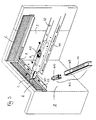
- Figure 3 shows the wall profile of Figure 1 together with a longitudinal room carrier 12.
- the wall bracket 4 is not present in the drawing for ease of understanding but would be present in a real situation.
- a room carrier 12 typically includes at least one carrier member 44 and a carrier end portion 40 at one or both of its ends.
- Each carrier end portion 40 is supported on a room carrier support portion, in this example the elongate ledge 22 of the wall profile 6.
- the carrier end portion 40 can be supported at any point along the length of the profile 6 and, whilst normally extending at right angles to the profile 6 may, instead, extend at almost any other angle in the horizontal or vertical planes.
- the end portion 40 is inserted into the end of the endmost carrier member 44 of the room carrier 12 and is fastened in position by a nut and bolt 42.
- the extent to which the end portion 40 projects from the end of the room carrier 12 preferably can be varied, so that the room carriers 12 do not need to be cut by the installer to precise lengths, if cut at all.
- the result of this arrangement, as shown in Figure 3 by arrows A, B and C, is that the installer has significant freedom in positioning the carriers.
- the room carriers 12 can also meet the wall profile 6 at an acute angle in the vertical plane, for instance, if the wall is not vertical and/or if the ceiling is not to be horizontal.
- the carrier end portion 40 is preferably composed of two separable parts, an end bracket 46 and a carrier joining portion 48.
- the carrier joining portion 48 has a slot 50 along its length which is engaged by a portion of the nut and bolt 42 and allows the variation in the extent to which the end portion 40 projects from the end of the room carrier 12.
- the length of the slot 50 is in the region of 50mm, thereby limiting the variation in the extent of projection of the carrier end portion 40 to the region of 50mm.
- the end bracket 46 may be exchangeable with different such end portions, for instance to provide different height dimensions for different types of ceiling panels.
- Figure 4 shows a second embodiment of the invention. This is the same as the first embodiment but in addition has an edge cover 14 inserted into the edge cover support portion 26 of the wall profile 6. All the variations discussed in respect of the first embodiment are similarly applicable to the second one and many other configurations.
- Figure 4 The central portion of Figure 4, that is the inside wall corner, shows the profile 6 in the same situation as that shown in Figure 3. Again the wall bracket 4 is omitted for ease of understanding. In normal use a series of room carriers 12 would also extend across the room from the wall profile 6, similarly to the room carrier shown in Figure 3. A dotted profile of a room carrier 12 is shown.
- the outside wall corner in Figure 4 shows an exploded view of a wall profile 6 and edge cover 14.
- the edge cover 14 is used to hide and finish off the gap between any ceiling panels and the wall 2.
- the edge cover 14 not only finishes off the gap between the panels and the wall but it can also be used to support the free ends of panels 18 which end at the wall. It is usually the last part of the system to be mounted, but is shown here without the panels 18 in position.
- Figure 5 For the arrangement of panels 18 reference will hereinafter be made to Figure 5.
- a spring retainer 60 is received in the edge cover support portion 26 shown in Figures 2a to 2c, in order to press the top of the edge cover 14 against the edge cover retaining portion 28 of the wall profile 6. This retains the edge cover 14 in position.
- Figure 5 shows a cross-section of a wall profile 6 supporting a longitudinal room carrier 12 and ceiling panels 18.
- the wall profile 6 is slightly different from that shown in Figures 2a to 2c.
- the design of edge cover 14 shown in Figure 5 is one suitable to support the panelling system shown, which uses panels 18 which are of a type and arrangement as described in the European Patent Application published as EP-A2-0,633,365.
- the edge cover 14 shown in Figure 5 has a vertical portion and a horizontal portion.
- the horizontal portion supports the cut off end of a panel 18 and is itself supported by the horizontal portion received in the edge cover support portion 26 of the wall profile 6.
- the edge cover 14 is also held in position by the spring retainer 60 slotted into the edge cover support portion 26 between the support portion 26 and the edge cover 14.
- a panel hold-down device 62 shown in Figure 5 as a leaf spring, holds the panel 18 down against the horizontal portion of the edge cover 14.
- the hold-down device 62 can take a number of forms, using resilience, its own mass or a mechanical fixing to hold the edge cover in place. Alternative methods are also possible for attaching the edge cover 14, to the wall profile 6, for instance using a hook to support the edge cover 14. However, preferably, the edge cover is held in a firm position as shown in Figure 5, using something at least equivalent to the spring retainer 60 shown.
- Figure 5 also shows in more detail the end bracket 46.
- This has an end bracket contact portion 52 which is in contact with the carrier support portion, that is the elongate ledge 22, transferring the weight from the room carrier 12 to the wall profile 6.
- a hook-under portion 54 which extends slightly beneath the elongate ledge 22 prevents accidental removal of the bracket end portion 46 from its support position, for instance should the room carrier 12 accidentally be lifted upwards.
- the wall profiles 6 of the present invention do not need to be carriers for the ceiling panels as well. Their function can be simply to support the room carriers 12 across the room. If used, edge covers can hold the ends of any panels 18. Perimeter profiles 6 are easy to fit, not only because the drill holes used for supporting them do not have to be drilled exactly, but also because, by using mounting brackets 4 the length of time that the profile must be supported from below, by whoever is assembling it, is not as great as when the profile itself must be screwed onto the wall.
- corner connectors 8 which may simply be pushed or pressed into a suitable channel or groove.
- the mounting system of the present invention is also useful, because the room carriers extending into the room area do not need to extend at a fixed angle from the profiles, but can extend at almost any angle in the horizontal and/or vertical planes. Thus, for instance, they can extend diagonally across a room.
- the ceiling panels used need not be square panels in a square grid, but can be lineal, triangular, trapezoidal, rhomboidal or in the form of parallelograms etc.
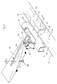
- FIG. 6 A further embodiment of the invention is shown in Figure 6. Illustrated in Figure 6 is the point where two room carrier members 44 meet end to end in a room where, as frequently happens, one room carrier member 44 is not sufficient to span the whole room.
- the ends of the carrier members 44 are connected by a splicing bracket 70. This clamps over the tops of the ends of the carrier members 44, as shown in Figure 6, and holds them by means of inwardly directed detents 72 which engage with apertures 56 in the carrier members' sides.
- the positions of the detents 72 and apertures 56 are such that any panel-holding elements on the carrier members 44, if there are any present, will remain spaced so that the look of the ceiling will not be disrupted. If, however, the panels are simply to be supported on top of the flanges 58 of the carrier members 44 then the designs of the splicing brackets 70 and carrier members 44 do not need to make provision for this.
- brackets 72 could instead be provided with resilient tongues which support the undersides of the tops of the carrier members 44, and preferably clamp them against the tops of the brackets themselves.
- Other engagement systems are also possible.
- the splicing bracket 70 is provided with a hanger rail 74 which allows it to be supported from a supporting hook 80.
- the hanger rail 74 has a longitudinal extent greater than the extent of the supporting hook 80 in the same direction.
- the hook 80 can support the bracket 70 in any position along the length of the rail 74, and can slide along the rail 74.
- the supporting hook 80 itself is height adjustably mounted on a screw threaded rod 82 which depends from a ceiling bracket 86.
- the height of the supporting hook 80 on the rod 82 is adjusted using a nut 84.
- the ceiling bracket 86 is attached to the structural ceiling 16 (see Figures 2a-c and Figure 5) using a fastener, such as a screw 88.
- the fastener 88 passes through a slot 90 on the ceiling bracket to allow the position of the ceiling bracket 86 to be adjusted.
- Other combinations of parts between the ceiling bracket 86 and splicing bracket 70 could be used instead.
- the mounting system of the present invention can be provided with only room carrier members 44 of limited and fixed lengths. These are easier to pack and ship than long ones or carrier members of many different lengths and consequently of easier utility to a non-skilled user. These lengths are preferably an integral multiple of the lengths of the intended or usual ceiling panels, e.g. 1x, 2x, 3x...
- the splicing brackets 70 can be used to support a room carrier 12 at any position along the carrier's length, and do not necessarily need to be used at the ends of carrier members 44. Also, where a splicing bracket 70 does join two carrier members 44 together, it is not necessary that that bracket 70 should be supported from above.
- the hanging system of the present invention is very versatile. It accommodates variation in quality of the ceiling, ease of access to parts of the ceiling and quick preparation of the ceiling for hanging carriers from it. An extra support hanger can be used where there is an additional load to be suspended, or where it is simply just easier, without requiring a completely different part for the job.
- these joins define natural positions for the intermediate suspension hangers, making it easy for a non-skilled user to use the system.
Landscapes
- Engineering & Computer Science (AREA)
- Architecture (AREA)
- Physics & Mathematics (AREA)
- Electromagnetism (AREA)
- Civil Engineering (AREA)
- Structural Engineering (AREA)
- Finishing Walls (AREA)
- Supports Or Holders For Household Use (AREA)
Claims (22)
- Système de montage pour supporter un plafond, comprenant :caractérisé en ce que :un profil périphérique (6)au moins une console de montage (4) destinée à être montée sur un support fixe (2) et qui est conçue pour recevoir et monter ledit profil périphérique (6) ; etun moyen d'enclenchement (10, 20, 24) qui positionne le profil périphérique (6) par rapport à la console de montage (4) dans au moins une première direction ;
ledit moyen d'enclenchement comprend une attache (10) sur ladite au moins une console de montage (4), laquelle attache (10) dans un premier mode empêche le mouvement dudit profil périphérique (6) par rapport à ladite au moins une console de montage (4) dans une seconde direction opposée à ladite première direction tout en permettant un mouvement relatif dans ladite première direction et en ce que ladite attache (10) dans un second mode empêche le déplacement relatif dudit profil périphérique (6) dans lesdites première et seconde directions. - Système de montage selon la revendication 1, dans lequel le mode de l'attache (10) est changé pour aller du premier mode au second mode en faisant pivoter l'attache par rapport à ladite console de montage (4).
- Système de montage selon la revendication 1 ou 2, dans lequel ledit moyen d'enclenchement (20, 24) comprend en outre une partie dentée (20) sur l'une desdites au moins une console de montage (4) et sur ledit profil périphérique (6) et un cliquet coopérant (30) sur l'autre desdites consoles de montage (4) et sur ledit profil périphérique (6).
- Système de montage selon la revendication 3, dans lequel la partie dentée (20) comprend des dents d'encliquetage (24) et ledit cliquet (30) est conçu pour s'enclencher avec au moins l'une des dents d'encliquetage (24).
- Système de montage selon l'une quelconques des revendications 3 ou 4, dans lequel l'attache (10) comprend en outre un verrou de blocage (34) qui permet que l'attache (10) soit bloquée sur une partie de la console de montage (4) empêchant de ce fait le déplacement relatif dudit profil périphérique dans la première et dans la seconde directions.
- Système de montage selon les revendications 3, 4 ou 5, dans lequel ledit mouvement relatif dudit profil (6) dans la seconde direction est empêché par ladite attache (10) qui s'enclenche avec au moins une dent (24) de ladite partie dentée (20).
- Système de montage selon l'une quelconque des revendications 3 à 6, dans lequel ladite attache comprend une attache à ressort (10) avec le cliquet (30) à une extrémité.
- Système de montage selon l'une quelconque des revendications 3 à 7, dans lequel ladite partie dentée (20) est droite.
- Système de montage selon l'une quelconque des revendications 3 à 8, dans lequel ladite partie dentée (20) est installée sur ledit profil périphérique (6).
- Système de montage selon l'une quelconque des revendications 3 à 9, dans lequel soit la partie dentée (20) et soit le cliquet (30) installés sur ledit profil périphérique (6) s'étend, en ayant une coupe transversale constante le long de la plus grande partie, si non sensiblement de la totalité de la longueur dudit profil (6).
- Système de montage selon l'une quelconque des revendications précédentes, dans lequel, en exploitation, ledit ajustement relatif dudit profil périphérique (6) dans ladite première direction est provoqué par le fait que ledit profil périphérique (6) est poussé vers le haut dans ledit moyen de montage (4).
- Système de montage selon l'une quelconque des revendications précédentes, dans lequel ledit profil périphérique (6) est pourvu d'un moyen de support d'au moins un panneau de plafond (18).
- Système de montage selon la revendication 12, dans lequel ledit moyen de support comprend un couvercle de bordure (14), en exploitation, monté sur ledit profil (6) de façon à pouvoir être enlevé, pour supporter au moins un bord d'au moins un panneau de plafond (18) ; et
un moyen de verrouillage (62) pour solliciter le au moins un bord à venir contre ledit couvercle de bord (14). - Système de montage selon l'une quelconque des revendications précédentes, dans lequel, en exploitation, ledit profil périphérique (6) est supporté seulement par ladite au moins une console de montage (4).
- Système de montage selon la revendication 14, dans lequel, en exploitation, ladite au moins une console de montage (4) est montée directement sur ledit support (2).
- Système de montage selon l'une quelconque des revendications précédentes, comprenant en outre au moins une plate-forme de local (12) dont une partie d'extrémité (40) est supportée, en exploitation, par ledit profil périphérique (6) ;
dans lequel ledit profil (6) comprend un moyen de support de plate-forme de local (22) destiné à supporter la partie d'extrémité (40) de ladite au moins une plate-forme de local ((12), et dans lequel la partie d'extrémité (40) de ladite au moins une plate-forme de local (12) et ledit moyen de support (22) sont agencés de telle façon que, en exploitation, l'angle entre ladite au moins une plate-forme de local (12) et ledit profil (6) peut être modifié autour d'un axe perpendiculaire à l'axe longitudinal du profil (6) et/ou d'un axe parallèle à l'axe longitudinal du profil (6). - Système de montage selon la revendication 16, dans lequel, ladite au moins une plate-forme de local (12) ou chacune de celles-ci comprend une pluralité d'éléments porteurs (44) ayant la même longueur, ladite longueur étant un multiple intégral de la longueur du ou d'un panneau de plafond (18) destiné à être porté par ledit système de montage.
- Système de support de plafond comprenant :un système de montage selon l'une quelconque des revendications précédentes ; etune console de raccordement (70) destinée à raccorder ensemble les extrémités des deux éléments porteurs (44) d'une plate-forme de local (12), la console de raccordement (70) comprenant :un moyen d'enclenchement (72) conçu pour enclencher lesdites deux extrémités en alignement l'une avec l'autre et pour supporter celles-ci ; etun moyen de support de console (74) grâce auquel ladite console de raccordement (70) et un élément porteur quelconque enclenché (44) ou bien des éléments (44) peuvent être supportés par le dessus, ledit moyen de support de console (74) comprenant un crochet de console ou une boucle de console.
- Système de support de plafond selon la revendication 18, dans lequel ledit moyen d'enclenchement comprend deux parties latérales opposées possédant des bossages orientés vers l'intérieur (72) pour s'enclencher avec des encoches ou des trous (56) prévus dans les côtés desdits éléments porteurs (44).
- Système de suspension de plafond comprenant :caractérisé en ce queun système de montage selon l'une quelconque des revendications 1 à 17 ou bien un système de support de plafond selon la revendication 18 ou 19 ; etun dispositif de suspension destiné à supporter une plate-forme de local (12) entre les deux extrémités de la plate-forme, le dispositif de suspension comprenant :une console de plafond (86) destinée à être fixée au plafond (16) grâce à des moyens de fixation (88) ;une tige (82) selon ladite console de plafond (86) ; etun moyen de support de plate-forme (80) destiné à supporter une plate-forme de local (12) à partir de celui-ci, qui est monté sur ladite tige (22) de manière à être ajusté pour obtenir un mouvement rotationnel relatif le long de ladite tige (82) ;ladite console de plafond (86) possède une fente à extrémité fermée (90) destinée à l'introduction à travers celle-ci dudit moyen de fixation (88), pour obtenir un mouvement rotatif et un mouvement coulissant entre ceux-ci ; etladite tige (82) est filetée.
- Système de suspension de plafond selon la revendication (20), comprenant en outre un écrou de réglage (84) sur ladite tige (82), sur lequel s'appuie le moyen de support de plate-forme (80) et grâce auquel la position axiale dudit moyen de support de plate-forme (80) peut être réglée sur ladite tige (82).
- Système de suspension de plafond selon la revendication 20 ou 21 qui dépend de la revendication 18 ou 19, dans lequel le moyen de support de console comprend une boucle (74) et dans lequel ledit moyen de support de plate-forme (80) comprend un crochet destiné à supporter ladite boucle (74).
Priority Applications (1)
| Application Number | Priority Date | Filing Date | Title |
|---|---|---|---|
| EP19970301649 EP0795657B1 (fr) | 1996-03-14 | 1997-03-12 | Système de montage pour plafonds suspendus |
Applications Claiming Priority (3)
| Application Number | Priority Date | Filing Date | Title |
|---|---|---|---|
| EP96301767 | 1996-03-14 | ||
| EP96301767 | 1996-03-14 | ||
| EP19970301649 EP0795657B1 (fr) | 1996-03-14 | 1997-03-12 | Système de montage pour plafonds suspendus |
Publications (3)
| Publication Number | Publication Date |
|---|---|
| EP0795657A2 EP0795657A2 (fr) | 1997-09-17 |
| EP0795657A3 EP0795657A3 (fr) | 1997-12-03 |
| EP0795657B1 true EP0795657B1 (fr) | 2001-10-24 |
Family
ID=26143606
Family Applications (1)
| Application Number | Title | Priority Date | Filing Date |
|---|---|---|---|
| EP19970301649 Expired - Lifetime EP0795657B1 (fr) | 1996-03-14 | 1997-03-12 | Système de montage pour plafonds suspendus |
Country Status (1)
| Country | Link |
|---|---|
| EP (1) | EP0795657B1 (fr) |
Families Citing this family (2)
| Publication number | Priority date | Publication date | Assignee | Title |
|---|---|---|---|---|
| US7677004B2 (en) | 2007-11-29 | 2010-03-16 | Usg Interiors, Inc. | Conformable wide wall angle |
| CN110948521B (zh) * | 2019-11-15 | 2021-01-29 | 聊城大学东昌学院 | 一种复杂工况下工业机器人柔性投放布置装置 |
Family Cites Families (4)
| Publication number | Priority date | Publication date | Assignee | Title |
|---|---|---|---|---|
| US4715161A (en) * | 1986-05-19 | 1987-12-29 | Erico International Corporation | Suspended ceiling grid clip |
| FR2627527B1 (fr) * | 1988-02-24 | 1990-07-13 | Profilage Pliage Metaux | Procede et patte de fixation de cornieres de rive pour plafond suspendu |
| US5201787A (en) * | 1991-05-31 | 1993-04-13 | Usg Interiors, Inc. | Trim system for suspension ceilings |
| NL9301668A (nl) * | 1993-09-28 | 1995-04-18 | Cornelis Erik Gerardus Maria V | Kantafwerkprofiel. |
-
1997
- 1997-03-12 EP EP19970301649 patent/EP0795657B1/fr not_active Expired - Lifetime
Also Published As
| Publication number | Publication date |
|---|---|
| EP0795657A3 (fr) | 1997-12-03 |
| EP0795657A2 (fr) | 1997-09-17 |
Similar Documents
| Publication | Publication Date | Title |
|---|---|---|
| US6971210B2 (en) | Accessible ceiling grid system | |
| US12006684B2 (en) | Ceiling grid hanger assembly with indexing tabs | |
| US5899036A (en) | Partition system | |
| US5335890A (en) | Ceiling track mounting apparatus | |
| US6168125B1 (en) | Adjustable railing bracket | |
| US7779593B2 (en) | Wall angle with pre-punched locating tabs | |
| US4070835A (en) | Device intended for the hooking of panels on a wall in order to constitute a covering on this wall | |
| US4709517A (en) | Floor-to-ceiling wall system | |
| US20020152704A1 (en) | Ceiling panel and support system | |
| US5077951A (en) | Suspended ceiling system | |
| CA2009596A1 (fr) | Dispositif de fixation pour assujettir un couronnement de panneau | |
| US20050034402A1 (en) | Torsion spring mount for suspended ceiling panels | |
| CN101316976B (zh) | 天花板模板系统 | |
| JP2021107647A (ja) | 雨樋支持構造 | |
| US6086029A (en) | Support system for wood framed construction | |
| EP0795657B1 (fr) | Système de montage pour plafonds suspendus | |
| JP2010095868A (ja) | 天井用補強ブレースの固定金具、および固定構造 | |
| EP0224374B1 (fr) | Assemblage pour plafond grillagé | |
| JP3079453B2 (ja) | 天井バー用連結金具 | |
| CA2333813A1 (fr) | Plafond suspendu | |
| JPH078689Y2 (ja) | 天井支持部材 | |
| JPH0642032Y2 (ja) | 下見張りタイルの施工構造 | |
| GB2255629A (en) | Louvre systems. | |
| JPH04189948A (ja) | 天井構造 | |
| JPH0449357A (ja) | 天井構造 |
Legal Events
| Date | Code | Title | Description |
|---|---|---|---|
| PUAI | Public reference made under article 153(3) epc to a published international application that has entered the european phase |
Free format text: ORIGINAL CODE: 0009012 |
|
| AK | Designated contracting states |
Kind code of ref document: A2 Designated state(s): BE DE ES FR GB IT NL |
|
| PUAL | Search report despatched |
Free format text: ORIGINAL CODE: 0009013 |
|
| AK | Designated contracting states |
Kind code of ref document: A3 Designated state(s): BE DE ES FR GB IT NL |
|
| 17P | Request for examination filed |
Effective date: 19980226 |
|
| 17Q | First examination report despatched |
Effective date: 19991122 |
|
| GRAG | Despatch of communication of intention to grant |
Free format text: ORIGINAL CODE: EPIDOS AGRA |
|
| GRAG | Despatch of communication of intention to grant |
Free format text: ORIGINAL CODE: EPIDOS AGRA |
|
| GRAH | Despatch of communication of intention to grant a patent |
Free format text: ORIGINAL CODE: EPIDOS IGRA |
|
| GRAH | Despatch of communication of intention to grant a patent |
Free format text: ORIGINAL CODE: EPIDOS IGRA |
|
| GRAA | (expected) grant |
Free format text: ORIGINAL CODE: 0009210 |
|
| AK | Designated contracting states |
Kind code of ref document: B1 Designated state(s): BE DE ES FR GB IT NL |
|
| PG25 | Lapsed in a contracting state [announced via postgrant information from national office to epo] |
Ref country code: IT Free format text: LAPSE BECAUSE OF FAILURE TO SUBMIT A TRANSLATION OF THE DESCRIPTION OR TO PAY THE FEE WITHIN THE PRESCRIBED TIME-LIMIT;WARNING: LAPSES OF ITALIAN PATENTS WITH EFFECTIVE DATE BEFORE 2007 MAY HAVE OCCURRED AT ANY TIME BEFORE 2007. THE CORRECT EFFECTIVE DATE MAY BE DIFFERENT FROM THE ONE RECORDED. Effective date: 20011024 Ref country code: FR Free format text: LAPSE BECAUSE OF FAILURE TO SUBMIT A TRANSLATION OF THE DESCRIPTION OR TO PAY THE FEE WITHIN THE PRESCRIBED TIME-LIMIT Effective date: 20011024 |
|
| REF | Corresponds to: |
Ref document number: 69707535 Country of ref document: DE Date of ref document: 20011129 |
|
| REG | Reference to a national code |
Ref country code: GB Ref legal event code: IF02 |
|
| PG25 | Lapsed in a contracting state [announced via postgrant information from national office to epo] |
Ref country code: DE Free format text: LAPSE BECAUSE OF FAILURE TO SUBMIT A TRANSLATION OF THE DESCRIPTION OR TO PAY THE FEE WITHIN THE PRESCRIBED TIME-LIMIT Effective date: 20020125 |
|
| PG25 | Lapsed in a contracting state [announced via postgrant information from national office to epo] |
Ref country code: GB Free format text: LAPSE BECAUSE OF NON-PAYMENT OF DUE FEES Effective date: 20020312 |
|
| PG25 | Lapsed in a contracting state [announced via postgrant information from national office to epo] |
Ref country code: ES Free format text: LAPSE BECAUSE OF FAILURE TO SUBMIT A TRANSLATION OF THE DESCRIPTION OR TO PAY THE FEE WITHIN THE PRESCRIBED TIME-LIMIT Effective date: 20020430 |
|
| EN | Fr: translation not filed | ||
| PLBE | No opposition filed within time limit |
Free format text: ORIGINAL CODE: 0009261 |
|
| STAA | Information on the status of an ep patent application or granted ep patent |
Free format text: STATUS: NO OPPOSITION FILED WITHIN TIME LIMIT |
|
| 26N | No opposition filed | ||
| GBPC | Gb: european patent ceased through non-payment of renewal fee |
Effective date: 20020312 |
|
| PGFP | Annual fee paid to national office [announced via postgrant information from national office to epo] |
Ref country code: NL Payment date: 20140308 Year of fee payment: 18 |
|
| PGFP | Annual fee paid to national office [announced via postgrant information from national office to epo] |
Ref country code: BE Payment date: 20140312 Year of fee payment: 18 |
|
| REG | Reference to a national code |
Ref country code: NL Ref legal event code: MM Effective date: 20150401 |
|
| PG25 | Lapsed in a contracting state [announced via postgrant information from national office to epo] |
Ref country code: NL Free format text: LAPSE BECAUSE OF NON-PAYMENT OF DUE FEES Effective date: 20150401 |
|
| PG25 | Lapsed in a contracting state [announced via postgrant information from national office to epo] |
Ref country code: BE Free format text: LAPSE BECAUSE OF NON-PAYMENT OF DUE FEES Effective date: 20150331 |