EP0224393A1 - Trennbarer Zusammenbau eines ein Entriegelungselement tragenden Kupplungsausrücklagers, insbesondere für Kraftfahrzeuge - Google Patents
Trennbarer Zusammenbau eines ein Entriegelungselement tragenden Kupplungsausrücklagers, insbesondere für Kraftfahrzeuge Download PDFInfo
- Publication number
- EP0224393A1 EP0224393A1 EP86402201A EP86402201A EP0224393A1 EP 0224393 A1 EP0224393 A1 EP 0224393A1 EP 86402201 A EP86402201 A EP 86402201A EP 86402201 A EP86402201 A EP 86402201A EP 0224393 A1 EP0224393 A1 EP 0224393A1
- Authority
- EP
- European Patent Office
- Prior art keywords
- clutch release
- release bearing
- drive
- assembly according
- decoupling
- Prior art date
- Legal status (The legal status is an assumption and is not a legal conclusion. Google has not performed a legal analysis and makes no representation as to the accuracy of the status listed.)
- Granted
Links
- 230000008878 coupling Effects 0.000 claims abstract description 132
- 238000010168 coupling process Methods 0.000 claims abstract description 132
- 238000005859 coupling reaction Methods 0.000 claims abstract description 132
- 238000003032 molecular docking Methods 0.000 claims abstract description 55
- 210000002105 tongue Anatomy 0.000 claims description 35
- 230000000295 complement effect Effects 0.000 claims description 6
- 230000035515 penetration Effects 0.000 claims description 2
- 230000009471 action Effects 0.000 description 9
- 238000000034 method Methods 0.000 description 6
- 230000008569 process Effects 0.000 description 6
- 230000008901 benefit Effects 0.000 description 5
- 239000000463 material Substances 0.000 description 4
- 210000000056 organ Anatomy 0.000 description 4
- 230000002441 reversible effect Effects 0.000 description 4
- 239000007787 solid Substances 0.000 description 4
- 239000002184 metal Substances 0.000 description 3
- 230000015572 biosynthetic process Effects 0.000 description 2
- 238000009434 installation Methods 0.000 description 2
- 238000012935 Averaging Methods 0.000 description 1
- 230000004323 axial length Effects 0.000 description 1
- 238000005452 bending Methods 0.000 description 1
- 239000000470 constituent Substances 0.000 description 1
- 238000010276 construction Methods 0.000 description 1
- 230000018109 developmental process Effects 0.000 description 1
- 238000006073 displacement reaction Methods 0.000 description 1
- 230000005489 elastic deformation Effects 0.000 description 1
- 230000002349 favourable effect Effects 0.000 description 1
- 238000002955 isolation Methods 0.000 description 1
- 230000014759 maintenance of location Effects 0.000 description 1
- 230000007246 mechanism Effects 0.000 description 1
- 238000000465 moulding Methods 0.000 description 1
- 230000002093 peripheral effect Effects 0.000 description 1
- 230000004044 response Effects 0.000 description 1
- 238000005096 rolling process Methods 0.000 description 1
- 238000000926 separation method Methods 0.000 description 1
- 229920002994 synthetic fiber Polymers 0.000 description 1
- 230000008719 thickening Effects 0.000 description 1
Images


Classifications
-
- F—MECHANICAL ENGINEERING; LIGHTING; HEATING; WEAPONS; BLASTING
- F16—ENGINEERING ELEMENTS AND UNITS; GENERAL MEASURES FOR PRODUCING AND MAINTAINING EFFECTIVE FUNCTIONING OF MACHINES OR INSTALLATIONS; THERMAL INSULATION IN GENERAL
- F16D—COUPLINGS FOR TRANSMITTING ROTATION; CLUTCHES; BRAKES
- F16D23/00—Details of mechanically-actuated clutches not specific for one distinct type
- F16D23/12—Mechanical clutch-actuating mechanisms arranged outside the clutch as such
- F16D23/14—Clutch-actuating sleeves or bearings; Actuating members directly connected to clutch-actuating sleeves or bearings
- F16D23/143—Arrangements or details for the connection between the release bearing and the diaphragm
- F16D23/144—With a disengaging thrust-ring distinct from the release bearing, and secured to the diaphragm
- F16D23/146—Arrangements for the connection between the thrust-ring and the release bearing
-
- Y—GENERAL TAGGING OF NEW TECHNOLOGICAL DEVELOPMENTS; GENERAL TAGGING OF CROSS-SECTIONAL TECHNOLOGIES SPANNING OVER SEVERAL SECTIONS OF THE IPC; TECHNICAL SUBJECTS COVERED BY FORMER USPC CROSS-REFERENCE ART COLLECTIONS [XRACs] AND DIGESTS
- Y10—TECHNICAL SUBJECTS COVERED BY FORMER USPC
- Y10S—TECHNICAL SUBJECTS COVERED BY FORMER USPC CROSS-REFERENCE ART COLLECTIONS [XRACs] AND DIGESTS
- Y10S192/00—Clutches and power-stop control
- Y10S192/01—Removable members
Definitions
- the present invention relates generally to the release bearings, in particular for a motor vehicle.
- the traction securing means used generally comprise, on the one hand, an elastically radially deformable annular coupling member, for example a simple rod, which is at least partially engaged radially in an annular groove of retaining formed for him on any of the parts to be joined in traction, and, on the other hand, a drive surface, which is formed generally transversely on the other of these parts, and with which said coupling member cooperates axially in support in the axial direction corresponding to the desired axial connection.
- an elastically radially deformable annular coupling member for example a simple rod, which is at least partially engaged radially in an annular groove of retaining formed for him on any of the parts to be joined in traction
- a drive surface which is formed generally transversely on the other of these parts, and with which said coupling member cooperates axially in support in the axial direction corresponding to the desired axial connection.
- the advantage of such an arrangement is that it allows the clutch release device to be controlled to be fitted in advance with the docking part, even before the corresponding clutch mechanism is assembled, and then, when the assembly of the assembly, the engagement by simple snap-fastening of the clutch release bearing with said docking part, and therefore with said declutching device.
- annular decoupling member which is put in place ahead of that of the parts to be joined in traction which comprises the drive range, at a distance therefrom, and with which, in response to sufficient axial movement of the clutch release bearing in the direction axially turned in the direction opposite to said drive surface, can engage said coupling member, by means of a constraint thereof.
- the coupling member being thus put under stress by the decoupling member, it drives with it the latter if the clutch release bearing is again the object of an axial displacement in the axial direction turned towards the drive surface , but, by the very fact of being put under stress, it then escapes this drive range, which effectively leads to the desired decoupling.
- the decoupling member itself escapes from the part that it originally fitted, and any new coupling is impossible, unless it is disconnected beforehand the decoupling member of the coupling member, and to return to their original place both of these members, or any new new members capable of being substituted for them, which is in practice operational particularly difficult to drive.
- this groove is formed in that of the parts to be secured in traction which comprises the drive range, and said drive range belongs to one of its sides.
- the decoupling member is found to have a frustoconical bearing which goes away radially from the bottom of the groove in which it is arranged, in the direction of the driving bearing, and whose circumference axially closest to said drive range is at least level with the circumference forming the free edge thereof.
- the decoupling member having remained in place, a new coupling is possible.
- the coupling member is a simple rod, that is to say in the case where this coupling member is in the form of a torus, and, for example , in the form of a torus of circular cross section.
- the decoupling member has an edge by which it comes into engagement with the decoupling member, the prior drive of which it must thus be the object can be assured for sure.
- the coupling member can be indifferently carried by the attack piece of the clutch release bearing or by the docking piece, the decoupling member being corollarily carried either by this docking piece or by this leading piece, it has since appeared that the arrangement according to which it is the leading piece of the clutch release bearing which carries the organ decoupling is particularly advantageous.
- the decoupling member Given its more extensive axial extension, the decoupling member experiences better sliding conditions on the part which carries it, which minimizes the risk of seeing it inadvertently bracing on it.
- this leading part already having by itself a sufficient axial length, taking into account the engagement stroke which must be its own when coupled with respect to the docking part, and this all the more so as , as a safety measure, this stroke is usually increased by an overtravel, and that such overtravel is also necessary for decoupling.
- the decoupling member the desired axial extension, it can also take advantage of the free space usually existing radially between the engaging part of the clutch release bearing and the coupling means, by example a cover, axially securing, within the latter, the attack element to which this attack piece belongs to the operating element specific to the control of the assembly.
- Another advantage of the arrangement with a decoupling member carried by the clutch release bearing is that, the clearance which is to be provided radially on the part corresponding attack for the intervention of the coupling member, and which, in practice, is formed by the groove provided on this attack piece for the decoupling member, is much less than that to be provided there when on the contrary, it must carry this coupling member, since, then, the latter must also be able to retract almost entirely therein.
- this clearance is of the order of half the radial thickness of the coupling member, and, in the second case, it is of the order of almost all of this thickness .
- the attack part of the clutch release bearing may have a smaller diameter, and, this attack part being in practice formed by one of the rings of a bearing with balls, this results in a significant saving, a ball bearing being usually all the more expensive as its average diameter is smaller.
- the positioning of this decoupling member on this attack piece can advantageously be done either by simple elasticity or by taking advantage of a slot which is provided radially for this purpose, since this installation implies a momentary increase in the diameter of this decoupling member, and not its retraction.
- the arrangements can advantageously be such that, when it is thus in place on the attacking part of the declutching stop, the decoupling member provides an annular clearance between it and the latter favorable to its good sliding. , and therefore to the proper functioning of the assembly, without the risk of seeing this play reduced or canceled under the request for radial retraction which is the object of the decoupling member on the part of the coupling member when it is engaged with it.
- this decoupling member when this decoupling member is opened radially by a slot, it suffices to do this, that, when it is in place on the leading part of the clutch release bearing, the two lips of its slot are in contact with one another.
- the present invention generally relates to a clutch release bearing assembly advantageously falling under such an arrangement with a decoupling member carried by the driving part of the clutch release bearing and advantageously free from the drawbacks briefly described above.
- a clutch release bearing assembly of the kind comprising, for coupling a clutch release bearing to the clutch disengaging device, a part, called for convenience docking part, which is suitably attached to said declutching device, and means for securing in traction, which, established between the docking part and a part, called for convenience attack part, belonging to the clutch release bearing, are capable of ensuring an axial connection between said parts in the axial direction going from the declutching device to said declutching stop, said traction securing means comprising, on the one hand, an annular coupling member, elastically deformable radially, which is at least partially engaged radially in a groove retaining ring formed for him on any one of said parts, and, on the other hand, a drive surface, which is formed generally transversely on the other of these ci, and with which said coupling member is able to cooperate axially bearing in the axial direction considered, and of the kind also comprising, for the decoupling of the clutch release bearing
- engagement means means is meant here means involving a certain relative interlocking between the coupling member and the decoupling member when these members are engaged with each other, unlike a simple support between such bodies as in French patent application No. 85 09883 mentioned above.
- the engagement means according to the invention may be formed by a groove that the decoupling member annularly has on its external periphery, this groove having a profile at least partly complementary to that of the coupling member.
- they are formed by at least one tongue, called here for simple convenience, drive tongue, which the decoupling member has axially, and which is elastically deformable radially, with, at rest, a free end which projects from the external periphery of this decoupling member, this drive tab having, itself, axially, in the vicinity of its free end, a profile at least in part complementary to that of the coupling member .
- decoupling On the one hand, on decoupling, it ensures, as desired, the driving of the coupling member by the decoupling member; and, on the other hand, on coupling, it ensures proper positioning of the decoupling member in the groove in which it is arranged, by coming, to do this, to cooperate momentarily in abutment with the corresponding edge of the piece of docking.
- such a drive tongue can also be provided in the case where the engagement means according to the invention comprise a groove.
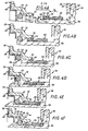
- the declutching device 11 which has only been shown diagrammatically, in broken lines in FIG. 1, is, in a manner known per se, formed by the end of the radial fingers of a diaphragm, c '' is to say of an annular part, which, belonging to the clutch to be controlled, comprises a circularly continuous peripheral part, forming a Belleville washer, for biasing engagement of this clutch, and a central part fragmented into radial fingers by slots, namely the radial fingers in question, for constituting levers specific to its control in release.
- this docking piece 13, or action piece is of the type described in the French patent application filed on April 11, 1983, under No. 83 05850, and published under No. 2.544 .036.
- the declutching device 11 comprises radially a flange 14, called a support flange, for action on such a declutching device 11, said support flange being suitably profiled for this purpose, and that in one piece with this flange support 14, it comprises, on the one hand, at its internal periphery, a bush 15, which, extending generally axially, passes axially through said declutching device 11, by means of the central opening 12 thereof , and, on the other hand, at its outer periphery, from place to place along the latter, tabs 16, which also pass axially through the declutching device 11, each between two adjacent radial fingers thereof, and which , each respectively, carry, circumferentially, cantilevered, at their end, in line with the support flange 14, and generally parallel to the latter, retaining fingers 17 suitable for ensuring, in cooperation with this support flange 14, the axial retention of the assembly on the declut
- the installation of such a docking piece 13 on the declutching device 11 is done according to a bayonet type mounting: after sufficient relative approximation of the docking piece 13 and of the declutching device 11, there is provided, axially, a relative bending, with respect to the others, of the end of each of the radial fingers of the declutching device 11 on which the circumference must engage the retaining finger 17 of the lugs 16 of the docking piece 13, then there is provided, circumferentially, a relative rotation, around the axis of the assembly, of said docking piece 13 with respect to said device clutch 11, so that such engagement actually takes place, and the previously bent radial fingers of the clutch device 11 are then released.
- the axial sleeve 15 of the docking piece 13 which is in practice of sheet metal suitably shaped, present, in its middle zone, between two generally rectilinear sections, a recess 18, that of its rectilinear sections which is axially the most distant from its support flange 14 having overall a smaller diameter than that of the other.
- the clutch release bearing 10 is also not, per se, part of the present invention.
- a driving element 20 by which it is adapted to act on the declutching device 11, by means of the docking part 13, as detailed below, an operating element 22, by which it is intended, in the embodiments shown, to be slidably mounted axially on any guide member, not shown, and coupling means which axially secure said attack element 20 to said operating element 22, and by which, in these embodiments, and as shown diagrammatically in broken lines in FIG. 1, it is also adapted to be actuated by a control member 24, constituted, for example, by a fork clutch release with fingers or arms 21.
- the driving element 20 is constituted by a ball bearing.
- the latter For cooperation with the docking part 13, the latter comprises a part 25, here called for convenience attack part.
- this leading part 25 is constituted by the internal ring of this ball bearing, the latter being sufficiently extended axially for this purpose in the direction of the declutching device 11.
- this inner ring is a solid piece suitably machined.
- the operating element 22 comprises, axially, a sleeve 26, by which it is adapted to be slidably engaged on the associated guide member, and, transversely, at the end of said sleeve 26 opposite to the driving element 20, for cooperation therewith, an annular flange 27.
- this annular flange 27 itself carries, axially projecting, coaxially with respect to the sleeve 26 and in the same direction as the latter, around the outer ring 29 of the ball bearing constituting the attack element 20, a crown 28.
- the coupling means axially securing this driving element 20 to the operating element 22 are constituted, in the embodiments shown, by a cover 30, which, by a skirt 31, is engaged without play on the crown 28 of the operating element 22.
- the cover 30 has, in the direction of the axis of the assembly, a fallen edge 33, against which bears, by its corresponding edge, the outer ring 29 of the ball bearing constituting the attack element 20, but which, for reasons which will appear below, stops largely at a distance from the outer ring of the latter, leaving annularly between it and it here is a free space E.
- the cover 30 forms, for the action of the fingers or arms 21 of the control member 24, two arms 34, which, in diametrically opposite positions with respect to the other, extend radially projecting in the direction opposite to the axis of the assembly.
- these arms 34 each have, parallel to the axis of the assembly, and in the direction of the declutching device 11, a square return 35, by which they bypass the arms or fingers 21 of the control member 24, and, at the end of this return angle 35, parallel to themselves, and in the direction of said axis of the assembly, a tab 36.
- latching means elastically deformable tabs being provided for this purpose in the ring 28 of the operating element 22 for cooperation with openings also provided for this purpose in the skirt 31 of the cover 30.
- a self-centering clutch release bearing with self-centering maintained there is provided, between the driving element 20 and the operating element 22, means axial action elastics, constituted, for example, as shown, by a wavy washer 37 of the type sold under the trade name "ONDUFLEX".
- this corrugated washer 37 bears on the annular flange 27 of the operating element 22, and it bears on the corresponding edge of the outer ring 29 of the ball bearing constituting the attack element 20 , for biasing of this outer ring against the fallen edge 33 of the cover 30.
- the docking piece 13 comprising an axially a bushing 15, and the latter being coaxial with the leading piece 25, it is between this bushing 15 and this leading piece 25 that said means for securing in traction are established.
- the leading part 25 is engaged in the bush 15 of the docking part 13, so that the means of fastening in traction in question intervene between the external periphery of this part d attack 25 and the internal periphery of this socket 15.
- annular coupling member 42 which is elastically deformable radially, and which is at least partially engaged radially in an annular retaining groove 43 formed for it on one of the parts 13, 25 in question, and, on the other hand, a drive surface 44, which is formed generally transversely on the other of said parts 13, 25, and with which it is able to cooperate axially bearing in the axial direction considered, that marked by the arrow F1 in FIG. 1.
- a decoupling member 46 mounted axially movable in a groove 47, which is arranged for it on that of the parts 13, 25 comprising the driving range 44, and whose said drive range 44 belongs to one of the sides.
- the coupling member 42 being carried by the docking piece 13, and the decoupling member 46 by the engaging part 25 of the declutching stop 10, said decoupling member 46 comprises, as detailed below, engagement means adapted to allow disengageable coupling with said coupling member 42, at less for the axial direction going from the declutching device 11 to said declutching stop 10.
- the retaining groove 43 provided for the coupling member 42 is formed in the docking piece 13, and the groove 47 provided as a corollary for the decoupling member 46 is formed on the leading piece 25 of the clutch release bearing 10.
- the retaining groove 43 is formed between the recess 18 that has the axial sleeve 15 of the docking piece 13 and a piece 49 attached thereto.
- this piece 49 is simply hooked by lugs 50 on the docking piece 13, on the side of the latter opposite the declutching device 11, in the region of the elbow formed by its flange d support 14 and its axial sleeve 15, said legs 50 passing through this support flange 14 in favor of the notches formed therein for the formation of associated legs 16 and being, beyond, folded down in contact with its opposite face .
- this piece 49 which is generally in the form of a bowl with bottom 52 largely perforated by a central opening 53 whose diameter is substantially the same as that of the inner periphery of the straight section further small diameter of the axial sleeve 15 of the docking piece 13; by its side wall 54 it is applied against the straight section of larger diameter of said axial sleeve 15; and by a flange 55, which is radially directed in the direction opposite to the axis of the assembly, and the legs 50 of which form, from place to place, extensions, it is applied against the support flange 14.
- the bottom 52 of the part 49 thus formed extends radially in the direction of the axis of the assembly and it faces the recess 18 of the axial sleeve 15.
- this flank 57 of the retaining groove 43 belongs to a part, namely part 49, which, distinct from the docking part 13, is integral with the latter.
- the other, 58, flanks of the retaining groove 43 that is to say that of its flanks which, formed by the recess 18 of the axial sleeve 15, is opposite to the drive surface 44, has, in the embodiments shown, from the bottom of this retaining groove 43, a first frustoconical bearing 59, and, following this, a second bearing frustoconical 60, which is of smaller conicity than that of the previous one, and which in practice extends to the internal periphery of the rectilinear section of smaller diameter of the axial sleeve 15.
- the retaining groove 43 widens outwards, from its bottom towards the external periphery of the attack piece 25.
- the coupling member 42 is formed by a simple rod.
- this coupling member 42 exhibits radially can result from the sole nature of the material which constitutes it.
- the rod that it forms being for example produced by simple rolling of a round wire.
- the coupling member 42 occupies a retracted configuration for which its outer diameter D1 is greater than that D2 of the outer periphery of the straight section of smaller diameter of the sleeve axial 15 of the attack piece 13.
- FIG. 4D due to its elasticity, it can take a deployed configuration, FIG. 4D for example, for which its radial engagement in the retaining groove 43 is accentuated.
- the decoupling member 46 is in the general form of a relatively flat ring, that is to say of a ring whose radial section is elongated parallel to its axis .
- the decoupling member 46 has a generally triangular profile.
- the radial elasticity of the decoupling member 46 can result from the sole nature of its constituent material.
- this slot 63 is in contact with one another, and there remains, between the decoupling member 46 and the bottom of the groove 47 in which it is arranged, an annular clearance J, Figure 2.
- the engagement means provided on the decoupling member 46 for its disengageable coupling with the coupling member 42 are formed by at least one tongue 64, called here simply for convenience drive tongue, that said decoupling member 46 has axially, and which is radially elastically deformable, with, at rest, a free end 65 which projects on the external periphery of this decoupling member 46.
- this drive tongue 64 extends over a circumference of diameter D 3 slightly greater than that D2 of the internal periphery of the rectilinear section of smaller diameter of the axial sleeve 15 of the workpiece. docking 13, FIG. 4A.
- the decoupling member 46 thus comprises, suitably distributed circularly, several identical drive tongues 64.
- the coupling member 42 being formed, as indicated above, by a simple rod in the embodiments shown, each of them has, axially, in the vicinity of its free end 65, in these embodiments, a profile at least partly complementary to that of said coupling member 42, and therefore, in practice, at least partly circular.
- the drive tongues 65 are, axially, entirely contained in the overall outline of the decoupling member 46.
- this frustoconical engagement surface 62 belongs to a portion of the decoupling member 46, which, distinct from the drive tongues 64, extends axially between the free end 65 of these drive tongues 64 and the drive surface 44.
- the decoupling member 46 has, transversely, in its central region, at a distance from the free end 65 of the drive tongues 64, and axially turned towards said free end 65 of these. ci, a shoulder 70.
- this shoulder 70 which affects the external periphery of the decoupling member 46, extends substantially in line with the rooting zone of the drive tongues 64 and the axial lugs 67 to the portion solid 69 of this decoupling member 46, so that the latter has, radially, a thickness greater than that in which said drive tongues 64 and said axial tabs 67 are formed.
- the thickening to which it leads for a position of the decoupling member 46 advantageously strengthens it.
- the decoupling member 46 is made of synthetic material, by molding of such a material, it comprises, at its outer periphery, in line with its drive tongues 64, grooves 73 axially scoring its massive portion 69 at the surface, for the passage of the punches suitable for the formation of the free end 65 of these drive tongues 64.
- the groove 47 in which the decoupling member 46 thus formed is axially movable has, in the embodiment shown, a straight flank 75, like that, corresponding, of said decoupling member 46.
- this groove 47 has, in the embodiment shown, a clearance 76 of profile suitable for allowing at least partial penetration of the organ decoupling 46.
- this profile is therefore generally triangular, like the corresponding one of the decoupling member 46.
- the clearance 76 which thus presents, in the manner of a simple puncture, the groove 47, is connected to the drive surface 44, and, in connection with the free edge thereof, the attack piece 25 of the clutch release bearing 10 comprises, on its outer periphery, a cylindrical surface 77 leaving a sufficient thickness of material between it and such a clearance 76.
- This cylindrical bearing is itself in connection with a frustoconical engagement bearing 78 which has, at its outer periphery, said engaging part 25, at its free axial end.
- This docking part 13 is equipped in advance with the coupling member 42, in the retaining groove 43 which it forms with the part 49 which is integral therewith, and, moreover, this coupling member 42 can occupy axially any place in this retaining groove 43, FIG. 4A.
- leading part 25 of the clutch release bearing 10 is equipped in advance with the decoupling member 46, in its groove 47, and the latter occupies any space therein axially.
- the clutch release bearing 10 is engaged axially, by its leading part 25, in the axial sleeve 15 of the docking part 13, as shown diagrammatically by the arrow F2 in FIG. 4A .
- the decoupling member 46 If, as indicated, the decoupling member 46 is then in the advanced position, the drive tongues 64 of this decoupling member 46 come, during this axial engagement, to abut by their free end 65 against the frustoconical bearing of engagement 19 of the docking piece 13, FIG. 4B, so that, thus stopped with respect to the disengaging stop 10, the decoupling member 46 moves in the groove 47 thereof in the direction of the end axial of this groove 47 opposite the drive surface 44.
- this phase can occur simultaneously with the previous one, or before or after it.
- the driving part 25 of the driving element 20 of the latter then comes to bear against the coupling member 42 by its drive surface 44, and, driving this coupling member 42 in the direction of the sidewall 58 of the retaining groove 43, it comes to apply it axially against the latter, and, more precisely, against its frustoconical bearing of lower conicity 60.
- the axial movement which it is necessary to apply to the release bearing 10, first in one direction, then in the other, for such coupling, can advantageously be printed blind using the control member 24, the fingers 21 thereof acting first on the lugs 36 of its cover 30, then on the arms 34 of this cover 30 whose previous lugs 36 form an extension.
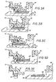
- this engagement of the decoupling member 46 in the coupling member 42 then extends to the free end 65 of its drive tabs 64, by radial elastic deformation of these- ci in the direction of the axis of the assembly, said drive tongues 64 then returning by elasticity to their initial configuration after crossing the coupling member 42, FIG. 5B.
- the section of smaller diameter of the axial sleeve 15 of the docking piece 13 is engaged in the free space E formed between the fallen edge 33 of the cover 30 and the piece d attack 25.
- the coupling member 42 is therefore coupled, but disengageably, to this decoupling member 46, at least in the axial direction from the declutching device 11 to the declutching stop 10.
- the taper of this frustoconical bearing 59 is such that, when, as indicated, the decoupling member 46 abuts against that of the sides of the groove 47 to which the driving bearing 44 belongs, the normal N to this frustoconical bearing 59 extends away from the associated engagement means, and therefore, in this case, away from the free end 65 of the drive tongues 64 of the decoupling member 46 .
- this normal N even extends also away from the groove 47.
- the contacting of the coupling member 42 with this cylindrical seat 77 is facilitated, on the one hand, by the fact that, by the engagement of the decoupling member 46 in the clearance 76 provided in the groove 47 at the base of the drive surface 44, the interval axially separating the free end 65 of the drive tabs 64 from the decoupling member 46 of this cylindrical surface 77 is advantageously reduced , and, on the other hand, by the fact that the normal N specified above also extends preferably away from this groove 47.
- the frustoconical engagement surface 62 of the decoupling member 46 belongs to the free end of its drive tongues 64.
- the corresponding portion of the decoupling member 46 is reduced to these drive tabs 64, without any axial tabs between them.
- the drive tabs 64 are capable of passing elastically from a deployed configuration, which is shown diagrammatically in broken lines in the figure, and for which they are able to come into abutment against the frustoconical bearing of engagement 19 of the docking piece 13 during the axial engagement therein of the attack piece 25 of the clutch release bearing 10, in a retracted configuration, which is shown in solid lines in the figure, and for which they are capable of coming to engage in the coupling member 42, for the deployment thereof which, according to the process described above, is necessary for decoupling.
- the attack piece 25, instead of being a solid piece suitably machined, is a sheet metal piece suitably shaped.
- the docking piece 13 is, in the embodiment shown, a solid piece suitably machined.
- the engagement means provided to allow the disengageable coupling of the decoupling member 46 with the coupling member 42 are formed by a groove 80 which annularly comprises, on its outer periphery, this decoupling member 46.
- this groove 80 has a profile at least partly complementary to that of the coupling member 42, and therefore a profile at least partly circular.
- this profile may be different, and for example quadrangular.
- a cylindrical surface may as well be provided between it and this one.
- the decoupling member 46 has, axially, at least one drive tab 64, and, in practice, a plurality of such drive tabs 64, which are elastically deformable radially, and whose end free 65, at rest, protrudes radially on its outer periphery.
- this free end 65 of the drive tongues 64 is axially at a distance from the groove 80, extending from the side of this groove opposite to the drive surface 44.
- the drive tongues 64 which, as before, are in one piece with the decoupling member 46, alternating with axial lugs 67 thereof, are, axially, all whole contained in the overall outline of this decoupling member 46.
- the decoupling member instead of being opened by a slot for its positioning on the attack piece which it must equip, may have, regularly distributed along one and the other of its axial end sections, notches, which, circularly alternated from one to the other of these sections, are axially nested from one to the other of these.
Landscapes
- Engineering & Computer Science (AREA)
- General Engineering & Computer Science (AREA)
- Mechanical Engineering (AREA)
- Mechanical Operated Clutches (AREA)
Applications Claiming Priority (2)
| Application Number | Priority Date | Filing Date | Title |
|---|---|---|---|
| FR8514934A FR2588338B1 (fr) | 1985-10-09 | 1985-10-09 | Montage de butee de debrayage reversible a organe de decouplage sur la butee de debrayage, notamment pour vehicule automobile |
| FR8514934 | 1985-10-09 |
Publications (2)
| Publication Number | Publication Date |
|---|---|
| EP0224393A1 true EP0224393A1 (de) | 1987-06-03 |
| EP0224393B1 EP0224393B1 (de) | 1989-12-27 |
Family
ID=9323661
Family Applications (1)
| Application Number | Title | Priority Date | Filing Date |
|---|---|---|---|
| EP86402201A Expired EP0224393B1 (de) | 1985-10-09 | 1986-10-06 | Trennbarer Zusammenbau eines ein Entriegelungselement tragenden Kupplungsausrücklagers, insbesondere für Kraftfahrzeuge |
Country Status (7)
| Country | Link |
|---|---|
| US (1) | US4733762A (de) |
| EP (1) | EP0224393B1 (de) |
| JP (1) | JPS6293523A (de) |
| BR (1) | BR8604904A (de) |
| DE (1) | DE3667825D1 (de) |
| ES (1) | ES2012350B3 (de) |
| FR (1) | FR2588338B1 (de) |
Cited By (2)
| Publication number | Priority date | Publication date | Assignee | Title |
|---|---|---|---|---|
| EP2455633A1 (de) * | 2010-11-23 | 2012-05-23 | ZF Friedrichshafen AG | Ausrückeinrichtung für eine gezogene Kraftfahrzeugkupplung |
| CN107110242A (zh) * | 2014-12-19 | 2017-08-29 | 法雷奥离合器公司 | 用于机动车辆的离合器用装置 |
Families Citing this family (16)
| Publication number | Priority date | Publication date | Assignee | Title |
|---|---|---|---|---|
| JPS62246628A (ja) * | 1986-04-18 | 1987-10-27 | Daikin Mfg Co Ltd | クラツチのレリ−ズベアリング機構 |
| FR2597560B1 (fr) * | 1986-04-18 | 1988-08-05 | Valeo | Montage de butee de debrayage, notamment pour vehicule automobile |
| GB8611221D0 (en) * | 1986-05-08 | 1986-06-18 | Automotive Prod Plc | Friction clutch |
| SE453216B (sv) * | 1986-05-14 | 1988-01-18 | Skf Nova Ab | Kopplingsanordning |
| DE3632884C2 (de) * | 1986-09-27 | 1995-04-27 | Fichtel & Sachs Ag | Gezogene Membranfederkupplung mit Schnappverbindung |
| JPS63145827A (ja) * | 1986-12-08 | 1988-06-17 | Daikin Mfg Co Ltd | クラツチのレリ−ズベアリング機構 |
| US4947975A (en) * | 1987-06-04 | 1990-08-14 | Kabushiki Kaisha Daikin Seisakusho | Release bearing mechanism of a clutch |
| FR2629884B1 (fr) * | 1988-04-08 | 1991-03-08 | Valeo | Butee de debrayage notamment pour vehicule automobile |
| FR2633354B1 (fr) * | 1988-06-23 | 1993-04-09 | Valeo | Montage pour l'assujettissement d'une piece d'accostage a un diaphragme, notamment pour vehicule automobile |
| FR2633353B1 (fr) * | 1988-06-23 | 1992-12-24 | Valeo | Ensemble d'accostage pour butee de debrayage, notamment pour vehicule automobile |
| FR2648201B1 (fr) * | 1989-06-07 | 1993-12-10 | Valeo | Ensemble d'accostage pour butee de debrayage, notamment pour vehicule automobile |
| KR930004649A (ko) * | 1991-08-17 | 1993-03-22 | 원본미기재 | 당김형태 마찰 클러치의 부정합체계 |
| US5653322A (en) * | 1996-01-30 | 1997-08-05 | Borg-Warner Automotive, Inc. | Two piece clutch assembly having twist lock joint |
| US6634866B2 (en) | 2001-08-17 | 2003-10-21 | Borgwarner, Inc. | Method and apparatus for providing a hydraulic transmission pump assembly having a one way clutch |
| US6588559B2 (en) | 2001-09-18 | 2003-07-08 | Borgwarner, Inc. | Two-way clutch biasing assembly |
| US6554113B2 (en) | 2001-09-20 | 2003-04-29 | Borgwarner, Inc. | Torque limiting accessory drive assembly |
Citations (2)
| Publication number | Priority date | Publication date | Assignee | Title |
|---|---|---|---|---|
| GB2062799A (en) * | 1979-11-06 | 1981-05-28 | Skf Kugellagerfabriken Gmbh | Assembly comprising a shaft removably held axially in a bore of a housing and a clutch release mechanism including such an assembly |
| EP0164871A1 (de) * | 1984-05-07 | 1985-12-18 | Automotive Products Public Limited Company | Ausrückvorrichtung für eine Reibungskupplung |
Family Cites Families (14)
| Publication number | Priority date | Publication date | Assignee | Title |
|---|---|---|---|---|
| FR2304826A1 (fr) * | 1975-03-19 | 1976-10-15 | Ferodo Sa | Mecanisme de commande en rotation notamment pour vehicule automobile, et embrayage et butee de debrayage propres a la realisation d'un tel mecanisme |
| DE2639766C2 (de) * | 1976-09-03 | 1986-01-09 | LuK Lamellen und Kupplungsbau GmbH, 7580 Bühl | Reibungskupplungseinheit |
| EP0044691B1 (de) * | 1980-07-22 | 1984-09-19 | Automotive Products Public Limited Company | Zieheinrichtung zum Lösen einer Kupplung |
| DE3119367C1 (de) * | 1981-05-15 | 1982-12-09 | Bayerische Motoren Werke AG, 8000 München | Vorrichtung zum hydraulischen Betaetigen einer gezogenen Reibungskupplung fuer Kraftfahrzeuge |
| FR2508125B1 (fr) * | 1981-06-18 | 1989-08-18 | Valeo | Butee de debrayage, notamment pour vehicule automobile, et son procede de montage |
| DE3150150A1 (de) * | 1981-12-18 | 1983-06-30 | Fichtel & Sachs Ag, 8720 Schweinfurt | Ausruecksystem fuer eine gezogene reibungskupplung mit verriegelungseinrichtung |
| EP0110602B1 (de) * | 1982-11-19 | 1988-01-07 | Automotive Products Public Limited Company | Reibungskupplung für ein Fahrzeug |
| FR2538060B1 (fr) * | 1982-12-15 | 1988-07-08 | Valeo | Montage de butee de debrayage, notamment pour vehicule automobile |
| FR2544036B1 (fr) * | 1983-04-11 | 1988-10-28 | Valeo | Piece d'accostage a rapporter sur le diaphragme d'un embrayage, et ensemble unitaire constitue par un tel diaphragme et une telle piece d'accostage |
| FR2545172B1 (fr) * | 1983-04-26 | 1986-03-21 | Valeo | Montage de butee de debrayage, piece d'accostage pour un tel montage et procedes de mise en place et de demontage du montage de butee |
| FR2557234B1 (fr) * | 1983-12-27 | 1989-03-31 | Valeo | Montage de butee de debrayage, et butee de debrayage propre a un tel montage |
| GB8404519D0 (en) * | 1984-02-21 | 1984-03-28 | Automotive Prod Plc | Friction clutch for vehicle |
| FR2580353B1 (fr) * | 1985-04-10 | 1990-07-20 | Automotive Products Plc | Mecanisme d'accouplement de butee d'embrayage pour vehicules automobiles |
| FR2588051B1 (fr) * | 1985-06-28 | 1987-12-18 | Valeo | Montage de butee de debrayage, notamment pour vehicule automobile |
-
1985
- 1985-10-09 FR FR8514934A patent/FR2588338B1/fr not_active Expired - Lifetime
-
1986
- 1986-10-06 DE DE8686402201T patent/DE3667825D1/de not_active Expired - Lifetime
- 1986-10-06 ES ES86402201T patent/ES2012350B3/es not_active Expired - Lifetime
- 1986-10-06 EP EP86402201A patent/EP0224393B1/de not_active Expired
- 1986-10-08 JP JP61240150A patent/JPS6293523A/ja active Pending
- 1986-10-08 US US06/916,805 patent/US4733762A/en not_active Expired - Lifetime
- 1986-10-08 BR BR8604904A patent/BR8604904A/pt not_active IP Right Cessation
Patent Citations (2)
| Publication number | Priority date | Publication date | Assignee | Title |
|---|---|---|---|---|
| GB2062799A (en) * | 1979-11-06 | 1981-05-28 | Skf Kugellagerfabriken Gmbh | Assembly comprising a shaft removably held axially in a bore of a housing and a clutch release mechanism including such an assembly |
| EP0164871A1 (de) * | 1984-05-07 | 1985-12-18 | Automotive Products Public Limited Company | Ausrückvorrichtung für eine Reibungskupplung |
Cited By (3)
| Publication number | Priority date | Publication date | Assignee | Title |
|---|---|---|---|---|
| EP2455633A1 (de) * | 2010-11-23 | 2012-05-23 | ZF Friedrichshafen AG | Ausrückeinrichtung für eine gezogene Kraftfahrzeugkupplung |
| CN107110242A (zh) * | 2014-12-19 | 2017-08-29 | 法雷奥离合器公司 | 用于机动车辆的离合器用装置 |
| CN107110242B (zh) * | 2014-12-19 | 2019-04-30 | 法雷奥离合器公司 | 用于机动车辆的离合器用装置 |
Also Published As
| Publication number | Publication date |
|---|---|
| JPS6293523A (ja) | 1987-04-30 |
| US4733762A (en) | 1988-03-29 |
| EP0224393B1 (de) | 1989-12-27 |
| DE3667825D1 (de) | 1990-02-01 |
| BR8604904A (pt) | 1987-07-07 |
| FR2588338B1 (fr) | 1990-03-30 |
| FR2588338A1 (fr) | 1987-04-10 |
| ES2012350B3 (es) | 1990-03-16 |
Similar Documents
| Publication | Publication Date | Title |
|---|---|---|
| EP0224393B1 (de) | Trennbarer Zusammenbau eines ein Entriegelungselement tragenden Kupplungsausrücklagers, insbesondere für Kraftfahrzeuge | |
| EP0300890B1 (de) | Schnellkupplung zwischen zwei Wellen oder dergleichen | |
| FR2544429A1 (fr) | Procede pour le montage d'une butee de debrayage, et butee de debrayage correspondante, notamment pour vehicule automobile | |
| FR2611009A1 (fr) | Butee de debrayage, notamment pour vehicule automobile | |
| FR2557234A1 (fr) | Montage de butee de debrayage, et butee de debrayage propre a un tel montage | |
| FR2544039A1 (de) | ||
| EP0243229B1 (de) | Zusammenbau eines Kupplungsausrücklagers, insbesondere für ein Kraftfahrzeug | |
| FR2544036A1 (fr) | Piece d'accostage a rapporter sur le diaphragme d'un embrayage, et ensemble unitaire constitue par un tel diaphragme et une telle piece d'accostage | |
| FR2545172A1 (fr) | Montage de butee de debrayage, piece d'accostage pour un tel montage et procedes de mise en place et de demontage du montage de butee | |
| EP0223645B1 (de) | Trennbarer Zusammenbau eines Kupplungsausrücklagers, insbesondere für Kraftfahrzeuge | |
| FR2524091A1 (fr) | Butee de debrayage, notamment pour vehicule automobile | |
| EP0272967B1 (de) | Kupplungsausrücklager mit bistabiler Federscheibe, insbesondere für Kraftfahrzeuge | |
| EP0192081B1 (de) | Zugkraftbetätigtes Kupplungslager | |
| FR2611244A1 (fr) | Butee de debrayage a piece elastique a action axiale, notamment pour vehicule automobile | |
| EP0220982B1 (de) | Aufstellung eines Kupplungsausrückers, insbesondere für ein Kraftfahrzeug | |
| FR2547002A1 (fr) | Butee de debrayage et outil de montage pour celle-ci | |
| EP0196947B1 (de) | Kupplungsausrücker, insbesondere für Kraftfahrzeug | |
| FR2618504A1 (fr) | Butee de debrayage, notamment pour vehicule automobile, et montage de butee de debrayage correspondant | |
| EP3885592B1 (de) | Blindmontageanordnung eines bremsseils an einem betätigungshebel einer kraftfahrzeug-trommelbremse und montageverfahren | |
| FR2557235A1 (fr) | Montage de butee de debrayage | |
| EP0190970B1 (de) | Kupplungsausrücker, insbesondere für Kraftfahrzeug | |
| FR2588051A1 (fr) | Montage de butee de debrayage, notamment pour vehicule automobile | |
| EP0211697A1 (de) | Selbstzentrierendes Ausrücklager mit einem radial elastischen Sprengring für eine Kupplung | |
| EP0205388B1 (de) | Zusammenbau eines Kupplungsrücklagers und Verfahren zum Zusammenstellen und Zerlegen desselben | |
| FR2701081A1 (fr) | Dispositif de débrayage à actionneur hydraulique à encliqueter sur un embrayage de type tiré et procédé pour sa mise en Óoeuvre au montage. |
Legal Events
| Date | Code | Title | Description |
|---|---|---|---|
| PUAI | Public reference made under article 153(3) epc to a published international application that has entered the european phase |
Free format text: ORIGINAL CODE: 0009012 |
|
| AK | Designated contracting states |
Kind code of ref document: A1 Designated state(s): DE ES FR GB IT |
|
| 17P | Request for examination filed |
Effective date: 19870713 |
|
| 17Q | First examination report despatched |
Effective date: 19880714 |
|
| GRAA | (expected) grant |
Free format text: ORIGINAL CODE: 0009210 |
|
| AK | Designated contracting states |
Kind code of ref document: B1 Designated state(s): DE ES FR GB IT |
|
| GBT | Gb: translation of ep patent filed (gb section 77(6)(a)/1977) | ||
| REF | Corresponds to: |
Ref document number: 3667825 Country of ref document: DE Date of ref document: 19900201 |
|
| ITF | It: translation for a ep patent filed | ||
| PLBE | No opposition filed within time limit |
Free format text: ORIGINAL CODE: 0009261 |
|
| STAA | Information on the status of an ep patent application or granted ep patent |
Free format text: STATUS: NO OPPOSITION FILED WITHIN TIME LIMIT |
|
| 26N | No opposition filed | ||
| PGFP | Annual fee paid to national office [announced via postgrant information from national office to epo] |
Ref country code: GB Payment date: 19920929 Year of fee payment: 7 |
|
| PGFP | Annual fee paid to national office [announced via postgrant information from national office to epo] |
Ref country code: ES Payment date: 19921031 Year of fee payment: 7 |
|
| PG25 | Lapsed in a contracting state [announced via postgrant information from national office to epo] |
Ref country code: GB Effective date: 19931006 |
|
| PG25 | Lapsed in a contracting state [announced via postgrant information from national office to epo] |
Ref country code: ES Free format text: LAPSE BECAUSE OF THE APPLICANT RENOUNCES Effective date: 19931007 |
|
| GBPC | Gb: european patent ceased through non-payment of renewal fee |
Effective date: 19931006 |
|
| ITTA | It: last paid annual fee | ||
| REG | Reference to a national code |
Ref country code: ES Ref legal event code: FD2A Effective date: 19991007 |
|
| PGFP | Annual fee paid to national office [announced via postgrant information from national office to epo] |
Ref country code: DE Payment date: 20011013 Year of fee payment: 16 |
|
| PGFP | Annual fee paid to national office [announced via postgrant information from national office to epo] |
Ref country code: FR Payment date: 20011030 Year of fee payment: 16 |
|
| PG25 | Lapsed in a contracting state [announced via postgrant information from national office to epo] |
Ref country code: DE Free format text: LAPSE BECAUSE OF NON-PAYMENT OF DUE FEES Effective date: 20030501 |
|
| PG25 | Lapsed in a contracting state [announced via postgrant information from national office to epo] |
Ref country code: FR Free format text: LAPSE BECAUSE OF NON-PAYMENT OF DUE FEES Effective date: 20030630 |
|
| REG | Reference to a national code |
Ref country code: FR Ref legal event code: ST |
|
| PG25 | Lapsed in a contracting state [announced via postgrant information from national office to epo] |
Ref country code: IT Free format text: LAPSE BECAUSE OF NON-PAYMENT OF DUE FEES;WARNING: LAPSES OF ITALIAN PATENTS WITH EFFECTIVE DATE BEFORE 2007 MAY HAVE OCCURRED AT ANY TIME BEFORE 2007. THE CORRECT EFFECTIVE DATE MAY BE DIFFERENT FROM THE ONE RECORDED. Effective date: 20051006 |