EP0224632B1 - Procédé et installation de purification de lubrifiants fluorés exempts d'hydrogène - Google Patents
Procédé et installation de purification de lubrifiants fluorés exempts d'hydrogène Download PDFInfo
- Publication number
- EP0224632B1 EP0224632B1 EP86105390A EP86105390A EP0224632B1 EP 0224632 B1 EP0224632 B1 EP 0224632B1 EP 86105390 A EP86105390 A EP 86105390A EP 86105390 A EP86105390 A EP 86105390A EP 0224632 B1 EP0224632 B1 EP 0224632B1
- Authority
- EP
- European Patent Office
- Prior art keywords
- lubricant
- fact
- process according
- vacuum pump
- pump
- Prior art date
- Legal status (The legal status is an assumption and is not a legal conclusion. Google has not performed a legal analysis and makes no representation as to the accuracy of the status listed.)
- Expired - Lifetime
Links
- 239000000314 lubricant Substances 0.000 title claims description 66
- 238000000034 method Methods 0.000 title claims description 21
- 238000000746 purification Methods 0.000 title claims 3
- 239000000463 material Substances 0.000 claims description 13
- PNEYBMLMFCGWSK-UHFFFAOYSA-N Alumina Chemical class [O-2].[O-2].[O-2].[Al+3].[Al+3] PNEYBMLMFCGWSK-UHFFFAOYSA-N 0.000 claims description 8
- 238000001914 filtration Methods 0.000 claims description 8
- 229930195733 hydrocarbon Natural products 0.000 claims description 8
- 150000002430 hydrocarbons Chemical class 0.000 claims description 8
- 239000000126 substance Substances 0.000 claims description 8
- 238000007872 degassing Methods 0.000 claims description 6
- 239000004215 Carbon black (E152) Substances 0.000 claims description 5
- 239000003463 adsorbent Substances 0.000 claims description 5
- 238000006073 displacement reaction Methods 0.000 claims description 5
- 239000012535 impurity Substances 0.000 claims description 5
- 230000000694 effects Effects 0.000 claims description 3
- 238000011084 recovery Methods 0.000 claims description 3
- VYPSYNLAJGMNEJ-UHFFFAOYSA-N Silicium dioxide Chemical compound O=[Si]=O VYPSYNLAJGMNEJ-UHFFFAOYSA-N 0.000 claims description 2
- 229910001570 bauxite Inorganic materials 0.000 claims description 2
- 238000004061 bleaching Methods 0.000 claims description 2
- 238000009530 blood pressure measurement Methods 0.000 claims description 2
- 239000002734 clay mineral Substances 0.000 claims description 2
- 239000000741 silica gel Substances 0.000 claims description 2
- 229910002027 silica gel Inorganic materials 0.000 claims description 2
- 239000003795 chemical substances by application Substances 0.000 claims 1
- 239000004927 clay Substances 0.000 claims 1
- 150000002148 esters Chemical class 0.000 claims 1
- 238000005325 percolation Methods 0.000 claims 1
- 238000004140 cleaning Methods 0.000 description 20
- 239000007789 gas Substances 0.000 description 11
- 239000000356 contaminant Substances 0.000 description 5
- 239000007788 liquid Substances 0.000 description 3
- 239000003921 oil Substances 0.000 description 3
- 229920000570 polyether Polymers 0.000 description 3
- 238000001179 sorption measurement Methods 0.000 description 3
- 150000008282 halocarbons Chemical class 0.000 description 2
- 239000002480 mineral oil Substances 0.000 description 2
- 238000005086 pumping Methods 0.000 description 2
- 239000007787 solid Substances 0.000 description 2
- 239000002904 solvent Substances 0.000 description 2
- XJDNKRIXUMDJCW-UHFFFAOYSA-J titanium tetrachloride Chemical compound Cl[Ti](Cl)(Cl)Cl XJDNKRIXUMDJCW-UHFFFAOYSA-J 0.000 description 2
- OKTJSMMVPCPJKN-UHFFFAOYSA-N Carbon Chemical compound [C] OKTJSMMVPCPJKN-UHFFFAOYSA-N 0.000 description 1
- JJLJMEJHUUYSSY-UHFFFAOYSA-L Copper hydroxide Chemical compound [OH-].[OH-].[Cu+2] JJLJMEJHUUYSSY-UHFFFAOYSA-L 0.000 description 1
- 229910003074 TiCl4 Inorganic materials 0.000 description 1
- QVGXLLKOCUKJST-UHFFFAOYSA-N atomic oxygen Chemical compound [O] QVGXLLKOCUKJST-UHFFFAOYSA-N 0.000 description 1
- 239000000440 bentonite Substances 0.000 description 1
- 229910000278 bentonite Inorganic materials 0.000 description 1
- SVPXDRXYRYOSEX-UHFFFAOYSA-N bentoquatam Chemical compound O.O=[Si]=O.O=[Al]O[Al]=O SVPXDRXYRYOSEX-UHFFFAOYSA-N 0.000 description 1
- 238000009835 boiling Methods 0.000 description 1
- 229910052799 carbon Inorganic materials 0.000 description 1
- KYKAJFCTULSVSH-UHFFFAOYSA-N chloro(fluoro)methane Chemical compound F[C]Cl KYKAJFCTULSVSH-UHFFFAOYSA-N 0.000 description 1
- 239000003245 coal Substances 0.000 description 1
- 238000005516 engineering process Methods 0.000 description 1
- 238000004880 explosion Methods 0.000 description 1
- 239000012530 fluid Substances 0.000 description 1
- 239000004519 grease Substances 0.000 description 1
- 238000010438 heat treatment Methods 0.000 description 1
- VHHHONWQHHHLTI-UHFFFAOYSA-N hexachloroethane Chemical compound ClC(Cl)(Cl)C(Cl)(Cl)Cl VHHHONWQHHHLTI-UHFFFAOYSA-N 0.000 description 1
- 238000004519 manufacturing process Methods 0.000 description 1
- 235000010446 mineral oil Nutrition 0.000 description 1
- 238000006386 neutralization reaction Methods 0.000 description 1
- 230000009965 odorless effect Effects 0.000 description 1
- 239000001301 oxygen Substances 0.000 description 1
- 229910052760 oxygen Inorganic materials 0.000 description 1
- 239000002245 particle Substances 0.000 description 1
- 230000000704 physical effect Effects 0.000 description 1
- -1 polytrifluorochloroethylene Polymers 0.000 description 1
- 239000000843 powder Substances 0.000 description 1
- 230000001105 regulatory effect Effects 0.000 description 1
- 230000000717 retained effect Effects 0.000 description 1
- 229920006395 saturated elastomer Polymers 0.000 description 1
- 239000000565 sealant Substances 0.000 description 1
- 239000004065 semiconductor Substances 0.000 description 1
- 230000001960 triggered effect Effects 0.000 description 1
- 238000011144 upstream manufacturing Methods 0.000 description 1
- 238000009849 vacuum degassing Methods 0.000 description 1
Images

Classifications
-
- C—CHEMISTRY; METALLURGY
- C10—PETROLEUM, GAS OR COKE INDUSTRIES; TECHNICAL GASES CONTAINING CARBON MONOXIDE; FUELS; LUBRICANTS; PEAT
- C10M—LUBRICATING COMPOSITIONS; USE OF CHEMICAL SUBSTANCES EITHER ALONE OR AS LUBRICATING INGREDIENTS IN A LUBRICATING COMPOSITION
- C10M175/00—Working-up used lubricants to recover useful products ; Cleaning
- C10M175/0075—Working-up used lubricants to recover useful products ; Cleaning synthetic oil based
-
- B—PERFORMING OPERATIONS; TRANSPORTING
- B01—PHYSICAL OR CHEMICAL PROCESSES OR APPARATUS IN GENERAL
- B01D—SEPARATION
- B01D19/00—Degasification of liquids
- B01D19/0068—General arrangements, e.g. flowsheets
Definitions
- the invention relates to a method for separating hydrocarbon contaminants from chemically inert lubricants such as perfluorinated polyethers, chlorofluorocarbons or the like, with the aid of a filter device.
- the invention also relates to devices suitable for carrying out this method.
- Perfluorinated polyethers are, for example, under the trade name “Fomblin” (trademark of Montedison) and chlorofluorocarbons for example under the trade name “Halocarbon” (Trademark of Halocarbon Products Company) available on the market.
- Other products equivalent to “Fomblin” are “Krytox” (DuPont), “Demnum” (Daikin), “Tyrenofluid” (Tyrenochemie) etc.
- the lubricant is contaminated with a wide variety of substances, e.g. with solids, liquids, gases and vapors.
- the aim of the invention is to clean contaminated lubricants of the type mentioned in the introduction and thus to make them reusable.
- Deep-bed filters with adsorbents are known per se (cf. "Hydrocarbon Processing", Volume 59, No. 9, Sept. 1980, page 218 and “Lubricants and Related Products", Klamann 1984, pages 70 to 73 and 84 to 87).
- the previously known filters are used exclusively for cleaning of lubricants containing hydrocarbons, ie the lubricants containing carbon should pass through the filter material, but the contaminants should not.
- the present invention has for its object to provide a method of the type mentioned, with which in a relatively simple way, and without the use of solvents or precipitants, a cleaning of fluorinated, ie hydrocarbon- free lubricants is possible.
- this object is achieved in that a filter device known per se, designed as a deep bed filter, is used which contains an adsorbent as filter material.
- a filter device of this type is not only able to retain mechanical contaminants, but also and in particular to separate hydrocarbon contaminants from the inert lubricants. If you select the filter bed sufficiently deep or if you let the lubricant to be cleaned flow through the filter bed several times, the result is a colorless and odorless fluid with the same physical properties (viscosity, refractive index, neutralization number, density) as the starting substance.
- An adsorbent for example activated aluminum oxide
- filter material for example in the form of activated Alumina or activated bauxite can be present.
- bleaching earth clay minerals such as B. bentonite, silica gel and the like are suitable as filter materials.
- Granular filter materials of this type have a large specific surface. They also have a high adsorption capacity for the dissolved impurities. Activated aluminum oxide in particular has a high adsorption capacity for dissolved hydrocarbons. Other liquid contaminants such as TiCl4 (titanium tetrachloride) are also retained. Finally, the filter material is suitable for retaining solid particles with a grain size down to the sub- ⁇ range.
- degassing stage expediently with a heater, in the line leading to the filter device. Due to the lower pressure and the elevated temperature, low-boiling or sublimating components (e.g. HF, HCl, C2Cl6) are separated in this stage.
- low-boiling or sublimating components e.g. HF, HCl, C2Cl6
- a commercially available lubricant-sealed positive-displacement vacuum pump as the cleaning device, which is equipped with a cleaning circuit for the lubricant.
- a prerequisite for the desired cleaning effect is that there is a filter device with activated aluminum oxide as filter material in this cleaning circuit.
- the lubricant in such a vacuum pump constantly flows in a circuit which leads from the oil box, which is usually under atmospheric pressure, via a feed pump through the filter device to the pumping chamber and then back into the oil box via the pump outlet. So in this cycle both find the desired one Filtration as well as vacuum degassing instead.
- the operation of vacuum pumps is also associated with an increase in the temperature of the lubricant, so that the degassing takes place in the scoop chamber at an elevated temperature.
- the vacuum pump is expediently equipped with a gas ballast device.
- a gas ballast device When the gas ballast is open, there is intensive mixing of the supplied air with the volatile substances, so that they are quickly and effectively removed from the lubricant to be cleaned.
- Fig. 1 shows schematically a device according to the invention. 1 designates a bed filter which contains activated aluminum oxide as filter material 2.
- Fluorinated lubricant to be cleaned is introduced into filter device 1 at 3. It leaves this through the outlet 4, which opens into the collecting container 5 via the degassing stage 9. This is with a sensor 6, for. B. a turbidimeter equipped with which the quality of the lubricant can be controlled.
- the vacuum pump 11 is connected to the degassing stage, which is shown schematically as a block. In this stage 9, volatile or condensable impurities are separated from the lubricant to be cleaned.
- the lubricant is fed via line 7 fed to the filter device 1 again, with the aid of the feed pump 8.
- the cleaned lubricant is discharged into the container 13 via the valve 12.
- a central control unit 14 is provided, to which the signals from sensor 6 are fed via line 15. Depending on these signals, the valve 12, the feed pump 8 and the vacuum pump 11 are actuated or started up or switched off via the control lines 16, 17 and 18.
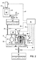
- Fig. 2 shows an embodiment in which a positive displacement vacuum pump 21 is used to clean the fluorinated lubricant.
- a schematically illustrated rotary vane vacuum pump is selected, the housing of which is designated by 22, scoop chamber by 23, rotor by 24, inlet by 25 and outlet by 26.
- the vacuum pump 21 is equipped with a lubricant circuit which includes the line 30 and the feed pump 27 and the filter device 28.
- the vacuum pump has a gas ballast device 29, which includes the valve 31.
- the entire amount of lubricant delivered by the feed pump 27 passes through the filter device 28 (main flow filter).
- the filter device can also be arranged in a bypass (bypass filter).
- the lubricant to be cleaned which is located in the oil sump 32, is transported through the filter device 28 by means of the feed pump 27.
- This filter device 28 again contains adsorption material, preferably activated aluminum oxide, as the filter material.
- the lubricant reaches the scoop chamber 23.
- the inlet of the vacuum pump remains closed during the cleaning operation.
- the volatile or condensable impurities are evaporated within the scooping chamber as a result of the low pressure and the increased temperature which is usually associated with the operation of the vacuum pump.
- the removal of the volatile substances is promoted by the connection of the gas ballast 29.
- the valve 31 is therefore open during the cleaning process.
- Lubricant cleaned in the filter device 28 and degassed in the scooping chamber 23 reaches the oeslump 32 again via the outlet 26.
- This is equipped with a sensor 6 with which the quality of the lubricant is monitored. If the desired degree of cleaning has not yet been reached, the vacuum pump 21 remains in operation. When the desired degree of cleaning has been reached, the pump 21 is switched off and the cleaned lubricant is discharged into the container 13 via the valve 12.
- a collecting container 33 for contaminated lubricant Upstream of the vacuum pump 21 is a collecting container 33 for contaminated lubricant. This is fed via line 3 and the coarse filter 34, the lubricant to be cleaned. From there it is fed discontinuously via the valve 35 to the vacuum pump 21.
- control line 14 again designates a central control and regulating unit which enables an automatically running cleaning operation.
- the control line 36 is used to actuate the valve 35.
- 37 denotes a line which leads to a pressure measuring device 38 connected to the inlet 25 of the pump. information about the vacuum achieved is then sent to the central unit 14.
- the vacuum pump 21 is started or stopped via the line 39.
- the feed pump 27 is switched on and off.
- the control line 41 enables the gas ballast 29 to be switched on and off.
- the control lines 15 and 16 serve to transmit information about the degree of purity of the liquid to be cleaned from the sensor 6 to the control unit 14 or to actuate the valve 12th
- the course of the cleaning process can e.g. B. take place in such a way that the desired amount of lubricant is let in via the valve 35 in the vacuum pump 21. This amount corresponds to the amount of lubricant that the selected vacuum pump usually requires.
- the vacuum pump 21 is started with the valves 12 and 35 closed and with the gas ballast valve 31 open, until the sensor 6 indicates that the desired degree of purity has been reached.
- the pressure measuring device 38 constantly reports the pressure reached to the central unit 9. The presence of volatile or condensable substances can be inferred from these pressure values, in particular when the gas ballast valve 31 is closed for the time of the pressure measurement.
- the pump 21 is switched off. Then the Drain the cleaned lubricant via the valve 12 into the container 13 and - after closing the valve 12 - refill the contaminated lubricant via the valve 35 into the vacuum pump 21.
- the vacuum pump used should have the lowest possible final pressure.
- the ratio of gas ballast to pumping speed should be as large as possible.
- the pump temperature should be as high as possible during gas ballast operation.
- the type of pump to be selected depends on the amount of fluorinated lubricant to be produced and cleaned.
- the particular advantage of the invention is that the cleaning of the fluorinated lubricant can be automated.
- the fact that a commercially available vacuum pump can be used means that the lubricant can be worked up directly by the user. The effort is minimal compared to the previously known cleaning processes.
- a centrifuge 42 is arranged in front of the collecting container 33. It consists of the container 43, which can be closed with the lid 44.
- the shaft of the centrifuge motor 45 passes through the cover 44.
- Conventional filter elements 46 containing contaminated fluorinated lubricant can be attached to the shaft 43 within the container 43. Filter elements of this type are frequently encountered in systems for the production of semiconductors. Spin-out lubricant flows through the coarse filter 34 into the collecting container 33.
- the operation of the centrifuge 42 can be included in the automatic sequence of the cleaning device.
- a filter cartridge 46 mounted beforehand in the centrifuge 42 can be centrifuged during a cleaning phase, which can be 1/2 to 5 hours depending on the amount of lubricant.
- the motor 45 can then be switched on and off by the control unit 14, which is connected to the centrifuge motor via the signal line 47.
- the centrifuge motor 45 and the vacuum pump 21 are switched off.
- the valve 12 opens and the cleaned lubricant is drained into the container 13.
- the valve 12 is closed, the valve 35 is opened and the lubricant is again contaminated Vacuum pump 21 filled.
- the valve 35 closes when the desired amount of lubricant is let into the vacuum pump 21.
- the lid 44 of the centrifuge 42 can be opened after the centrifuge motor 45 is switched off, the ejected filter element 46 can be exchanged for another filter element and the functional sequence described can be started again after the lid 44 is closed.
Landscapes
- Chemical & Material Sciences (AREA)
- Chemical Kinetics & Catalysis (AREA)
- Engineering & Computer Science (AREA)
- Combustion & Propulsion (AREA)
- General Chemical & Material Sciences (AREA)
- Oil, Petroleum & Natural Gas (AREA)
- Organic Chemistry (AREA)
- Lubricants (AREA)
- Treatment Of Liquids With Adsorbents In General (AREA)
- Solid-Sorbent Or Filter-Aiding Compositions (AREA)
Claims (14)
- Procédé pour séparer, de lubrifiants fluorés non hydrogénés, comme des esters perfluorés, des fluorochlorures de carbone ou analogues, les impuretés du type hydrocarbures, à l'aide d'un dispositif de filtration, procédé caractérisé par le fait que l'on emploie un dispositif de filtration (1, 28) connu en soi, qui est conçu sous forme de lit filtrant profond et qui contient comme matériau filtrant (2) un agent d'adsorption.
- Procédé selon la revendication 1, caractérisé par le fait que l'on emploie comme matériau filtrant (2) de l'oxyde d'aluminium activé ou un agent contenant de l'oxyde d'aluminium activé.
- Procédé selon la revendication 1, caractérisé par le fait que l'on emploie comme matériau filtrant (2) de l'alumine, de la bauxite, de la terre décolorante, des minéraux argileux, du gel de silice ou analogues.
- Procédé selon la revendication 1, 2 ou 3, caractérisé par le fait que le lubrifiant à épurer passe plusieurs fois en parcours cyclique, par le dispositif de filtration (1, 28) et par un étage de dégazage (9, 23).
- Procédé selon la revendication 4, caractérisé par le fait que dans la zone de l'étage de dégazage (9, 23), on chauffe le lubrifiant à épurer.
- Procédé selon l'une des revendications 1 à 5, caractérisé par le fait qu'après son passage à travers le dispositif de filtration (1), on collecte le lubrifiant à épurer dans un récipient de collecte (5) et qu'on y contrôle les caractéristiques du lubrifiant à épurer à l'aide d'au moins un détecteur (6).
- Procédé selon l'une des revendications 1 à 6, caractérisé par le fait que l'on emploie une pompe à vide à refoulement (21) étanche au lubrifiant, de préférence une pompe à palettes, par le fait que l'on emploie, comme lubrifiant pour la pompe à vide (21), le lubrifiant à épurer et par le fait que le lubrifiant passe, en parcours cyclique, à travers le dispositif de filtration (28) avec le moyen d'adsorption.
- Procédé selon la revendication 7, caractérisé par le fait que l'on emploie une pompe à vide à refoulement avec un dispositif de charge de gaz (29) et que pendant la marche de la pompe l'arrivée de la charge de gaz est ouverte.
- Procédé selon lar evendication 7 ou 8, caractérisé par le fait que l'on mesure la pression au voisinage de l'entrée, fermée, de la pompe et que cette mesure sert au contrôle de l'effet d'épuration en ce qui concerne les substances volatiles.
- Procédé selon la revendication 8 ou 9, caractérisé par le fait que l'on ferme l'arrivée de la charge de gaz pendant la mesure de la pression.
- Installation pour la mise en oeuvre du procédé selon l'une des revendications 8 ou 9, caractérisée par le fait qu'elle est une pompe à vide à refoulement (21), étanche au lubrifiant, avec un puisard d'huile (32), de préférence une pompe à palettes, qui présente un dispositif (29) de charge de gaz et un parcours cyclique du lubrifiant passant par le dispositif de filtration (28) et qu'à son entrée (25), habituellement fermée, est relié un manomètre (38).
- Installation selon la revendication 11, caractérisée par le fait qu'un récipient de collecte (33) pour le lubrifiant non épuré est relié avec le puisard d'huile (32) par l'intermédiaire d'une conduite équipée d'une vanne (35).
- Installation selon la revendication 12, caractérisée par le fait qu'en amont du récipient de collecte (33) est installée une centrifugeuse (42) pour la récupération du lubrifiant inerte provenant des éléments filtrants.
- Installation selon l'une des revendications 11 à 14, caractérisée par le fait qu'une unité de commande (14) est prévue pour permettre un déroulement largement automatique de la récupération et de l'épuration du lubrifiant inerte et de l'épuration qui fait suite.
Applications Claiming Priority (2)
| Application Number | Priority Date | Filing Date | Title |
|---|---|---|---|
| DE3543162 | 1985-12-06 | ||
| DE19853543162 DE3543162A1 (de) | 1985-12-06 | 1985-12-06 | Vorrichtung zur reinigung wasserstofffreier fluorierter schmiermittel |
Publications (2)
| Publication Number | Publication Date |
|---|---|
| EP0224632A1 EP0224632A1 (fr) | 1987-06-10 |
| EP0224632B1 true EP0224632B1 (fr) | 1992-08-26 |
Family
ID=6287805
Family Applications (1)
| Application Number | Title | Priority Date | Filing Date |
|---|---|---|---|
| EP86105390A Expired - Lifetime EP0224632B1 (fr) | 1985-12-06 | 1986-04-18 | Procédé et installation de purification de lubrifiants fluorés exempts d'hydrogène |
Country Status (4)
| Country | Link |
|---|---|
| US (1) | US4756825A (fr) |
| EP (1) | EP0224632B1 (fr) |
| JP (1) | JPS62138592A (fr) |
| DE (2) | DE3543162A1 (fr) |
Families Citing this family (3)
| Publication number | Priority date | Publication date | Assignee | Title |
|---|---|---|---|---|
| FR2695044B1 (fr) * | 1992-09-03 | 1994-11-04 | Alsthom Gec | Procédé de traitement de fluide à base d'ester-phosphate d'un circuit hydraulique. |
| EP0926226A1 (fr) * | 1997-12-22 | 1999-06-30 | C.S. Filtration S.p.r.l. | Filtration d'huiles synthétiques par produit silico-calcaire |
| CN111100750A (zh) * | 2018-10-29 | 2020-05-05 | 台境企业股份有限公司 | 废氟素油的处理方法及系统 |
Family Cites Families (10)
| Publication number | Priority date | Publication date | Assignee | Title |
|---|---|---|---|---|
| DE1004322B (de) * | 1953-12-10 | 1957-03-14 | Carborundum Co | Vorrichtung zur Regenerierung von gebrauchtem OEl |
| US3448042A (en) * | 1966-03-28 | 1969-06-03 | Day & Zimmermann Inc | Process for concentrating organic material from an aqueous stream |
| GB1215422A (en) * | 1968-04-05 | 1970-12-09 | Nagynyomasu Kiserleti Intezet | Process for pre-treating used lubricating oils |
| NL6908459A (fr) * | 1969-06-04 | 1970-12-08 | ||
| FR2219969B1 (fr) * | 1973-03-01 | 1978-09-08 | Lubrifiants Nx Ent Hydrocarbur | |
| US3870033A (en) * | 1973-11-30 | 1975-03-11 | Aqua Media | Ultra pure water process and apparatus |
| JPS6052190B2 (ja) * | 1982-10-08 | 1985-11-18 | 神奈川県 | フロン系合成潤滑油の廃油の精製方法 |
| DE3237930C1 (de) * | 1982-10-13 | 1984-04-05 | Leybold-Heraeus GmbH, 5000 Köln | Reinigung von wasserstoff-freien,fluorierten Schmiermitteln |
| IT1173444B (it) * | 1984-03-15 | 1987-06-24 | Montedison Spa | Procedimento per la decontaminazione esauriente degli olii perfluoropolieteri |
| IL79985A0 (en) * | 1985-09-13 | 1986-12-31 | Ausimont Spa | Purification of oils containing solid matter in suspension |
-
1985
- 1985-12-06 DE DE19853543162 patent/DE3543162A1/de not_active Withdrawn
-
1986
- 1986-04-18 EP EP86105390A patent/EP0224632B1/fr not_active Expired - Lifetime
- 1986-04-18 DE DE8686105390T patent/DE3686557D1/de not_active Expired - Fee Related
- 1986-04-22 US US06/854,855 patent/US4756825A/en not_active Expired - Fee Related
- 1986-05-30 JP JP61123829A patent/JPS62138592A/ja active Pending
Also Published As
| Publication number | Publication date |
|---|---|
| JPS62138592A (ja) | 1987-06-22 |
| EP0224632A1 (fr) | 1987-06-10 |
| DE3686557D1 (de) | 1992-10-01 |
| DE3543162A1 (de) | 1987-06-11 |
| US4756825A (en) | 1988-07-12 |
Similar Documents
| Publication | Publication Date | Title |
|---|---|---|
| DE69017639T2 (de) | Reinigung von Druckluft-Kondensat. | |
| DE69636619T2 (de) | Methode und vorrichtung zur filtration, entgasung, dehydratierung und entfernung von alterungsprodukten von ölquellen | |
| DE4208506C2 (de) | Entsorgungsvorrichtung und Verfahren zum Abscheiden von Öl aus Schmutzwasser | |
| DE907646C (de) | Verfahren und Vorrichtung zur Filterung von Fluessigkeiten | |
| EP0224632B1 (fr) | Procédé et installation de purification de lubrifiants fluorés exempts d'hydrogène | |
| DD249639A5 (de) | Reinigung von oelen, die suspendierte feststoffe enthalten | |
| US3575842A (en) | Recovering tar from tar sand | |
| DE69509725T2 (de) | Sprühvorrichtung zum Trennen von Feststoffen aus Fluiden | |
| DE869938C (de) | Verfahren und Vorrichtung zur Reinigung und Trocknung komprimierter Gase | |
| DE202011100486U1 (de) | Einrichtung zur Abfallbeseitigung | |
| DE3325203C2 (fr) | ||
| DE102006018725B4 (de) | Anlage zum Filtern von Kühl- oder Bearbeitungsmedien für Trenn-, Schleif- und Erodierprozesse | |
| DE4300493C2 (de) | Verfahren zum Schlammabschneiden | |
| DE4400612A1 (de) | Abscheideranlage | |
| DE2127643B2 (de) | Verfahren zur gewinnung von kakaobutter | |
| DE2401116A1 (de) | Filtervorrichtung und verfahren zum regenerieren eines filterelements | |
| DE3322599C2 (fr) | ||
| EP0563646A1 (fr) | Dispositif de filtration à courant transversal avec pompe de circulation immergée | |
| DE857489C (de) | Verfahren und Vorrichtung zur Extraktion von Schwefel aus schwefelhaltigen Massen, insbesondere Gasreinigungsmassen, mittels eines Loesungsmittels | |
| US4631068A (en) | Removal of sulfur from aqueous suspension using filtration | |
| DE4012104A1 (de) | Zusatzeinrichtung fuer separator | |
| DE69602350T2 (de) | Verfahren und apparat zur elektrostatischen reinigung von organischen flüssigkeiten | |
| DD260007A1 (de) | Verfahren zum regenerieren einer im kreislauf gefuehrten verschmutzten oel-wasser-emulsion | |
| AT394498B (de) | Verfahren und vorrichtung zum abtrennen von feststoffteilchen aus fluessigen und gasfoermigen medien | |
| DE9206238U1 (de) | Querstromfiltrationsanlage mit Eintauch-Umwälzpumpe |
Legal Events
| Date | Code | Title | Description |
|---|---|---|---|
| PUAI | Public reference made under article 153(3) epc to a published international application that has entered the european phase |
Free format text: ORIGINAL CODE: 0009012 |
|
| AK | Designated contracting states |
Kind code of ref document: A1 Designated state(s): CH DE FR GB IT LI |
|
| 17P | Request for examination filed |
Effective date: 19870901 |
|
| RAP1 | Party data changed (applicant data changed or rights of an application transferred) |
Owner name: LEYBOLD AKTIENGESELLSCHAFT |
|
| 17Q | First examination report despatched |
Effective date: 19880922 |
|
| ITF | It: translation for a ep patent filed | ||
| GRAA | (expected) grant |
Free format text: ORIGINAL CODE: 0009210 |
|
| AK | Designated contracting states |
Kind code of ref document: B1 Designated state(s): CH DE FR GB IT LI |
|
| REF | Corresponds to: |
Ref document number: 3686557 Country of ref document: DE Date of ref document: 19921001 |
|
| GBT | Gb: translation of ep patent filed (gb section 77(6)(a)/1977) | ||
| ET | Fr: translation filed | ||
| PGFP | Annual fee paid to national office [announced via postgrant information from national office to epo] |
Ref country code: FR Payment date: 19930310 Year of fee payment: 8 |
|
| PGFP | Annual fee paid to national office [announced via postgrant information from national office to epo] |
Ref country code: CH Payment date: 19930315 Year of fee payment: 8 |
|
| PGFP | Annual fee paid to national office [announced via postgrant information from national office to epo] |
Ref country code: GB Payment date: 19930316 Year of fee payment: 8 |
|
| PGFP | Annual fee paid to national office [announced via postgrant information from national office to epo] |
Ref country code: DE Payment date: 19930322 Year of fee payment: 8 |
|
| ITTA | It: last paid annual fee | ||
| PLBE | No opposition filed within time limit |
Free format text: ORIGINAL CODE: 0009261 |
|
| STAA | Information on the status of an ep patent application or granted ep patent |
Free format text: STATUS: NO OPPOSITION FILED WITHIN TIME LIMIT |
|
| 26N | No opposition filed | ||
| PG25 | Lapsed in a contracting state [announced via postgrant information from national office to epo] |
Ref country code: GB Effective date: 19940418 |
|
| PG25 | Lapsed in a contracting state [announced via postgrant information from national office to epo] |
Ref country code: LI Effective date: 19940430 Ref country code: CH Effective date: 19940430 |
|
| GBPC | Gb: european patent ceased through non-payment of renewal fee |
Effective date: 19940418 |
|
| PG25 | Lapsed in a contracting state [announced via postgrant information from national office to epo] |
Ref country code: FR Effective date: 19941229 |
|
| REG | Reference to a national code |
Ref country code: CH Ref legal event code: PL |
|
| PG25 | Lapsed in a contracting state [announced via postgrant information from national office to epo] |
Ref country code: DE Effective date: 19950103 |
|
| REG | Reference to a national code |
Ref country code: FR Ref legal event code: ST |
|
| PG25 | Lapsed in a contracting state [announced via postgrant information from national office to epo] |
Ref country code: IT Free format text: LAPSE BECAUSE OF NON-PAYMENT OF DUE FEES;WARNING: LAPSES OF ITALIAN PATENTS WITH EFFECTIVE DATE BEFORE 2007 MAY HAVE OCCURRED AT ANY TIME BEFORE 2007. THE CORRECT EFFECTIVE DATE MAY BE DIFFERENT FROM THE ONE RECORDED. Effective date: 20050418 |