EP0224732B1 - Dispositif relatif à un moteur à combustion interne suralimenté - Google Patents
Dispositif relatif à un moteur à combustion interne suralimenté Download PDFInfo
- Publication number
- EP0224732B1 EP0224732B1 EP86115222A EP86115222A EP0224732B1 EP 0224732 B1 EP0224732 B1 EP 0224732B1 EP 86115222 A EP86115222 A EP 86115222A EP 86115222 A EP86115222 A EP 86115222A EP 0224732 B1 EP0224732 B1 EP 0224732B1
- Authority
- EP
- European Patent Office
- Prior art keywords
- combustion engine
- internal combustion
- bypass air
- exhaust gas
- conduit
- Prior art date
- Legal status (The legal status is an assumption and is not a legal conclusion. Google has not performed a legal analysis and makes no representation as to the accuracy of the status listed.)
- Expired
Links
Images


Classifications
-
- F—MECHANICAL ENGINEERING; LIGHTING; HEATING; WEAPONS; BLASTING
- F02—COMBUSTION ENGINES; HOT-GAS OR COMBUSTION-PRODUCT ENGINE PLANTS
- F02B—INTERNAL-COMBUSTION PISTON ENGINES; COMBUSTION ENGINES IN GENERAL
- F02B37/00—Engines characterised by provision of pumps driven at least for part of the time by exhaust
- F02B37/12—Control of the pumps
- F02B37/18—Control of the pumps by bypassing exhaust from the inlet to the outlet of turbine or to the atmosphere
-
- F—MECHANICAL ENGINEERING; LIGHTING; HEATING; WEAPONS; BLASTING
- F01—MACHINES OR ENGINES IN GENERAL; ENGINE PLANTS IN GENERAL; STEAM ENGINES
- F01N—GAS-FLOW SILENCERS OR EXHAUST APPARATUS FOR MACHINES OR ENGINES IN GENERAL; GAS-FLOW SILENCERS OR EXHAUST APPARATUS FOR INTERNAL-COMBUSTION ENGINES
- F01N3/00—Exhaust or silencing apparatus having means for purifying, rendering innocuous, or otherwise treating exhaust
- F01N3/08—Exhaust or silencing apparatus having means for purifying, rendering innocuous, or otherwise treating exhaust for rendering innocuous
- F01N3/10—Exhaust or silencing apparatus having means for purifying, rendering innocuous, or otherwise treating exhaust for rendering innocuous by thermal or catalytic conversion of noxious components of exhaust
- F01N3/24—Exhaust or silencing apparatus having means for purifying, rendering innocuous, or otherwise treating exhaust for rendering innocuous by thermal or catalytic conversion of noxious components of exhaust characterised by constructional aspects of converting apparatus
- F01N3/30—Arrangements for supply of additional air
- F01N3/34—Arrangements for supply of additional air using air conduits or jet air pumps, e.g. near the engine exhaust port
-
- F—MECHANICAL ENGINEERING; LIGHTING; HEATING; WEAPONS; BLASTING
- F02—COMBUSTION ENGINES; HOT-GAS OR COMBUSTION-PRODUCT ENGINE PLANTS
- F02B—INTERNAL-COMBUSTION PISTON ENGINES; COMBUSTION ENGINES IN GENERAL
- F02B37/00—Engines characterised by provision of pumps driven at least for part of the time by exhaust
- F02B37/12—Control of the pumps
- F02B37/16—Control of the pumps by bypassing charging air
- F02B37/168—Control of the pumps by bypassing charging air into the exhaust conduit
-
- Y—GENERAL TAGGING OF NEW TECHNOLOGICAL DEVELOPMENTS; GENERAL TAGGING OF CROSS-SECTIONAL TECHNOLOGIES SPANNING OVER SEVERAL SECTIONS OF THE IPC; TECHNICAL SUBJECTS COVERED BY FORMER USPC CROSS-REFERENCE ART COLLECTIONS [XRACs] AND DIGESTS
- Y02—TECHNOLOGIES OR APPLICATIONS FOR MITIGATION OR ADAPTATION AGAINST CLIMATE CHANGE
- Y02A—TECHNOLOGIES FOR ADAPTATION TO CLIMATE CHANGE
- Y02A50/00—TECHNOLOGIES FOR ADAPTATION TO CLIMATE CHANGE in human health protection, e.g. against extreme weather
- Y02A50/20—Air quality improvement or preservation, e.g. vehicle emission control or emission reduction by using catalytic converters
-
- Y—GENERAL TAGGING OF NEW TECHNOLOGICAL DEVELOPMENTS; GENERAL TAGGING OF CROSS-SECTIONAL TECHNOLOGIES SPANNING OVER SEVERAL SECTIONS OF THE IPC; TECHNICAL SUBJECTS COVERED BY FORMER USPC CROSS-REFERENCE ART COLLECTIONS [XRACs] AND DIGESTS
- Y02—TECHNOLOGIES OR APPLICATIONS FOR MITIGATION OR ADAPTATION AGAINST CLIMATE CHANGE
- Y02T—CLIMATE CHANGE MITIGATION TECHNOLOGIES RELATED TO TRANSPORTATION
- Y02T10/00—Road transport of goods or passengers
- Y02T10/10—Internal combustion engine [ICE] based vehicles
- Y02T10/12—Improving ICE efficiencies
Definitions
- the invention relates to a device on a supercharged internal combustion engine, in particular for motor vehicles, according to the preamble of patent claim 1.
- a generic internal combustion engine is described in DE-A-2 647 836.
- a three-way valve is provided which, depending on a fuel controller at low engine load, directs a portion of the charge air via a recirculation line in front of the exhaust gas turbocharger turbine. This is intended to keep the speed of the exhaust gas turbocharger high, particularly when idling and in the lower part-load range of the internal combustion engine, so that an adequate boost pressure is available as quickly as possible during acceleration.
- afterburning is additionally achieved.
- This afterburning which can optionally be brought about by a suitable fuel metering on the internal combustion engine, also contributes to the boost pressure increase during idling, in overrun mode or during partial load operation of the internal combustion engine.
- the object of the invention is to produce targeted afterburning in the exhaust pipe system, improved boost pressure control and combustion air delivery in the lower speed range of the internal combustion engine by means of measures on the recirculation valve.
- the measures according to the invention therefore do not transfer combustion air into the exhaust gas pipe system continuously, but periodically in the extension phase.
- the particular advantage here is the targeted controllability of the air supply both in terms of time and, if appropriate, the quantity and distribution.
- the air supply can thus take place in such a way that the air recirculation valve is closed in the event of pressure peaks, flow flashbacks, etc.
- the extension phase or depending on the power, flow and ignition conditions fuel content rich or lean
- the air supply can take place briefly before or after, so that a safe, uniform re-ignition is achieved with a high average exhaust pressure and the turbine of the exhaust gas turbocharger is kept at high speed.
- the air recirculation valve can be controlled or controlled according to the features of claim 2 via an operating device of the internal combustion engine.
- the operating device can be, for example, the crankshaft or the camshaft of the internal combustion engine, which drives a rotary valve as a recirculating air valve by means of a toothed belt. With a defined transmission ratio between the crankshaft or camshaft, it is then ensured that the air recirculation valve is always open during the extension phase of the one or more cylinders.
- the ignition device of the internal combustion engine could be used as the operating device for actuation.
- the ignition pulse for one cylinder may serve as an opening pulse for another cylinder that is currently in the extension phase.
- a defined amount of circulating air can be fed directly to the machine outlet in the extension phase. Since the exhaust gases here still have a very high temperature, a reliable post-ignition with good post-combustion efficiency can be achieved if a sufficient quantity of recirculated air is supplied. If necessary, however, an introduction of the circulating air directly into the exhaust manifold of the internal combustion engine can be sufficient to achieve satisfactory afterburning.
- a preferred measure for controlling the degree of afterburning and thus for influencing the boost pressure and the required power directly via the recirculation valve is stated in claim 4.
- the boost pressure can be reduced or excess temperatures avoided by reducing the amount of circulating air.
- the amount of circulating air can be changed depending on the current load of the internal combustion engine.
- the air supply can also be completely interrupted via this volume control, for. B. in the event of overheating of the exhaust gas turbocharger.
- a change in the time of flow with respect to the exhaust gas ejection phase earlier or later can be advantageous depending on the temperature of the exhaust gas, the surrounding exhaust pipe system and in particular on the speed of the internal combustion engine or the exhaust gas flow rate and, if applicable, the burning rate during the afterburning.
- the air recirculation valve can be a rotary valve driven by the internal combustion engine according to the features of claims 5 to 8.
- This rotary valve can be driven in a two-stroke internal combustion engine with crankshaft speed and in a four-stroke internal combustion engine with camshaft speed, so that a phase assignment to the gas exchange control of the internal combustion engine is ensured.
- the circulating air can advantageously be distributed through the rotor of the circulating air valve, whereby both the flow rate and the time of flow can be adjusted by means of an adjusting sleeve with flow openings arranged around this rotor.
- a four-stroke reciprocating piston internal combustion engine 10 with five cylinders 1 to V has outlet channels 12 and inlet channels 14 for the gas exchange.
- the gas exchange control takes place in a known manner via gas exchange valves and valve actuation elements, not shown, which are driven by a camshaft 16.
- the exhaust gases of the internal combustion engine 10 are fed via an exhaust manifold 18 and an exhaust manifold 20 to the exhaust gas turbine 22 of an exhaust gas turbocharger 24, not shown. After flowing through the exhaust gas turbine 22, the exhaust gases are discharged into the atmosphere via an exhaust system 26, not shown. If the exhaust gas supply is too high, exhaust gas can be directed past the exhaust gas turbine 22 via a bypass line 28 and a blow-off valve 30.
- the exhaust gas turbine 22 drives a compressor 32, which sucks in combustion air via an air filter 34 and an air mass meter 36 of a fuel metering device, not shown, and conveys this via a charge air line 38 and a distributor suction pipe 40 to the inlet channels 14 of the internal combustion engine 10.
- a charge air cooler 42 and an arbitrarily controllable throttle valve 44 are provided in the charge air line 38 downstream of the compressor 32. By means of a line 46 bypassing the throttle valve 44 with a control valve 48, both an idle charge control and a charge increase during overrun can be carried out.
- a circulating air line 50 branches off from the charge air line 38 and leads to a circulating air valve 52.
- the air recirculation valve 52 has an outlet 54, 56, 58, 60, 62 distributed over its circumference per cylinder of the internal combustion engine, which are connected to the exhaust gas channels 12 of the internal combustion engine via individual lines 64, 66, 68, 70, 72.
- the rotor of the air recirculation valve 52 is driven by a crankshaft 74 with a gear 76 from which the toothed belt 78, which also drives the camshaft 16, is driven by the crankshaft of the internal combustion engine.
- the gear ratio is 2: 1.
- An electric servomotor 80 which is controlled by an electronic control unit 82, is attached to the air recirculation valve 52.
- the control unit 82 the load a of the internal combustion engine 10, for. B. according to the position of the throttle valve 44, the speed n and the temperature T of the internal combustion engine 10, the temperature T A of the exhaust gas turbocharger 24, and the boost pressure P in the boost pressure line downstream of the compressor 32, however, upstream of the throttle valve 44.
- These data are evaluated in the control unit 82 and the air recirculation valve 52 or its flow rate and time of flow are adjusted in accordance with a map stored in the control unit 82.
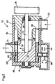
- the air recirculation valve 52 (FIG. 2) is a rotary valve with an annular housing part 84 with an end wall 86, into which a housing section 90 provided with an angled air duct 88 is inserted.
- a rotor 92 is rotatably mounted in this housing via the shaft 74 and roller bearings 94, 96.
- the rotor 92 in which an angled air duct 98, which is connected to the air duct 88, is formed, runs through small gaps without contact with the housing and an adjusting sleeve 100, which is axially displaceable and rotatable in the housing part 84.
- the adjusting sleeve 100 is provided over its circumference with 5 flow openings 102, the oval opening cross section of which can be seen from FIG. 3. In the position shown, these openings 102 overlap with the outflow openings of the outlets 54, 56, 58, 60, 62 in the housing part 84, the outflow openings being made larger in the circumferential direction (cf. FIG. 3, outflow opening 54).
- the opening of the air duct 98 in the rotor 92 adjacent to the adjusting sleeve 100 conforms to the throughflow openings 102.
- a spur toothing 104 is incorporated over a defined circumferential area, into which an adjusting gear 106 of the servomotor 80, which is not shown in more detail, engages.
- the adjusting gear 106 can - as indicated by the arrows 108, 110 - be rotated or axially displaced, with one Rotation, the adjusting sleeve 100 is rotated about its axis of rotation coinciding with the axis of rotation of the shaft 74 and is displaced in the event of a displacement along this axis of rotation.
- the throughflow time which is determined by the overlap of the air duct 98 in the rotor 92 with the corresponding throughflow opening 102, sooner or later Relation to exhaust gas phase out.
- the flow rate can be reduced from 0 to the largest possible cross section.
- the exhaust gas duct 12 which is open to the air recirculation line, is thus supplied with additional combustion air from the boost pressure line 38 during the exhaust gas ejection phase, so that reliable post-ignition and post-combustion take place. If a pre-adjustment or post-adjustment of the throughflow time or a reduction in the throughflow quantity is to take place, then the electric servomotor 80 is controlled via the control unit 82 and the adjusting sleeve 100 is correspondingly rotated or axially displaced by means of the adjusting gear 106.
- the invention is not restricted to the exemplary embodiment shown.
- the cross sections of the throughflow or outflow openings can also be round, rectangular or asymmetrically profiled; the latter to achieve a progressive or degressive opening characteristic.
- the rotor can be designed in the manner of a pinhole.
Landscapes
- Engineering & Computer Science (AREA)
- Chemical & Material Sciences (AREA)
- Combustion & Propulsion (AREA)
- Mechanical Engineering (AREA)
- General Engineering & Computer Science (AREA)
- Chemical Kinetics & Catalysis (AREA)
- Health & Medical Sciences (AREA)
- Toxicology (AREA)
- Supercharger (AREA)
- Exhaust-Gas Circulating Devices (AREA)
- Valve Device For Special Equipments (AREA)
Claims (9)
Priority Applications (1)
| Application Number | Priority Date | Filing Date | Title |
|---|---|---|---|
| AT86115222T ATE39275T1 (de) | 1985-12-04 | 1986-11-03 | Vorrichtung an einer aufgeladenen brennkraftmaschine. |
Applications Claiming Priority (2)
| Application Number | Priority Date | Filing Date | Title |
|---|---|---|---|
| DE3542782 | 1985-12-04 | ||
| DE19853542782 DE3542782A1 (de) | 1985-12-04 | 1985-12-04 | Vorrichtung an einer aufgeladenen brennkraftmaschine |
Publications (2)
| Publication Number | Publication Date |
|---|---|
| EP0224732A1 EP0224732A1 (fr) | 1987-06-10 |
| EP0224732B1 true EP0224732B1 (fr) | 1988-12-14 |
Family
ID=6287537
Family Applications (1)
| Application Number | Title | Priority Date | Filing Date |
|---|---|---|---|
| EP86115222A Expired EP0224732B1 (fr) | 1985-12-04 | 1986-11-03 | Dispositif relatif à un moteur à combustion interne suralimenté |
Country Status (3)
| Country | Link |
|---|---|
| EP (1) | EP0224732B1 (fr) |
| AT (1) | ATE39275T1 (fr) |
| DE (2) | DE3542782A1 (fr) |
Families Citing this family (5)
| Publication number | Priority date | Publication date | Assignee | Title |
|---|---|---|---|---|
| ZA928107B (en) * | 1991-10-23 | 1993-05-07 | Transcom Gas Tech | Boost pressure control. |
| JP2746559B2 (ja) * | 1994-12-30 | 1998-05-06 | 現代自動車株式会社 | 車両における空気汚染排出物質低減装置 |
| DE102012009355B4 (de) * | 2011-12-09 | 2022-01-05 | Audi Ag | Abgasreinigungseinrichtung sowie Brennkraftmaschinenanordnung |
| DE102014015526B4 (de) | 2014-10-20 | 2020-07-16 | Audi Ag | Verfahren zum Betreiben einer Brennkraftmaschine |
| CN107725175B (zh) * | 2017-10-18 | 2024-03-26 | 山东交通学院 | 一种弹簧振子共振式脉冲能量延迟释放涡轮增压系统 |
Family Cites Families (5)
| Publication number | Priority date | Publication date | Assignee | Title |
|---|---|---|---|---|
| BE555740A (fr) * | ||||
| DE1929126A1 (de) * | 1968-06-15 | 1970-06-18 | Uzina 23 August | Verfahren zur Abgasturboladung in Abzweigung fuer Verbrennungsmotoren |
| SE338208B (fr) * | 1970-10-19 | 1971-08-30 | O Peltomaeki | |
| US4534173A (en) * | 1981-10-19 | 1985-08-13 | Honda Giken Kogyo Kabushiki Kaisha | Means for supplying a secondary air in an internal combustion engine which is provided with a turbo charger |
| DE3311626C2 (de) * | 1983-03-30 | 1986-09-25 | M.A.N. Maschinenfabrik Augsburg-Nürnberg AG, 8900 Augsburg | Aufgeladene Vier-Takt-Brennkraftmaschine |
-
1985
- 1985-12-04 DE DE19853542782 patent/DE3542782A1/de not_active Withdrawn
-
1986
- 1986-11-03 DE DE8686115222T patent/DE3661432D1/de not_active Expired
- 1986-11-03 AT AT86115222T patent/ATE39275T1/de active
- 1986-11-03 EP EP86115222A patent/EP0224732B1/fr not_active Expired
Also Published As
| Publication number | Publication date |
|---|---|
| DE3661432D1 (en) | 1989-01-19 |
| ATE39275T1 (de) | 1988-12-15 |
| EP0224732A1 (fr) | 1987-06-10 |
| DE3542782A1 (de) | 1987-06-11 |
Similar Documents
| Publication | Publication Date | Title |
|---|---|---|
| DE3631474C2 (fr) | ||
| EP1095210B1 (fr) | Dispositif de commande de charge et procede pour assurer la commande d'un moteur a combustion interne a piston alternatif | |
| EP0454943B1 (fr) | Turbo-compresseur pour un moteur à combustion interne | |
| DE102004032589B4 (de) | Brennkraftmaschine mit Abgasnachbehandlung und Verfahren zu deren Betrieb | |
| EP0885352B1 (fr) | Moteur a allumage par etincelle avec surcompresseur a ondes de pression | |
| EP1396619A1 (fr) | Système de suralimentation pour un moteur à combustion interne | |
| DE2836870A1 (de) | Kraftfahrzeug mit abgasturbolader | |
| EP2370687A1 (fr) | Machine à combustion interne | |
| DE60023168T2 (de) | Verfahren zum vermindern der emissionen in einer brennkraftmaschine | |
| WO2017037093A1 (fr) | Procédé et dispositif de retraitement des gaz d'échappement d'un moteur à combustion interne | |
| EP2801714A1 (fr) | Moteur à combustion interne doté de cylindre débrayable et procédé de fonctionnement d'un tel moteur à combustion interne | |
| DE3735736A1 (de) | Vorrichtung zum steuern einer turboladeranlage | |
| DE19547285C2 (de) | Vorrichtung zum Reduzieren von Schadstoffemissionen eines Verbrennungsmotors für Fahrzeuge | |
| EP0221312B1 (fr) | Système d'admission pour moteur à allumage commandé à injection électronique de carburant | |
| EP0899436A1 (fr) | Moteur à combustion interne comprenant un échangeur d'ondes de pression | |
| DE2904947A1 (de) | Verteiler-einspritzpumpe fuer mit kompressionszuendung arbeitende mehrzylinder-verbrennungsmotoren | |
| EP0224732A1 (fr) | Dispositif relatif à un moteur à combustion interne suralimenté | |
| DE19932119C2 (de) | Fremdgezündete Hubkolbenbrennkraftmaschine | |
| DE19623970C2 (de) | Aufgeladener Verbrennungsmotor mit einer Abgasrückführungsleitung | |
| DE4104011C1 (en) | IC engine control system - uses EGR and low heat conduction inlet manifold with matching of inlet air to injected fuel volume | |
| DE3601700A1 (de) | Mehrzylindrige brennkraftmaschine mit kraftstoffeinspritzung, insbesondere turbomotor | |
| DE3801463C1 (fr) | ||
| DE102018117124B4 (de) | Verbrennungsmotor und Verfahren zur Abgasnachbehandlung eines solchen Verbrennungsmotors | |
| DE102015200047B4 (de) | Verfahren zum Betreiben einer Brennkraftmaschine mit Teilabschaltung | |
| DE102021107433A1 (de) | Verbrennungsmotor sowie Verfahren zum Betreiben eines Verbrennungsmotors |
Legal Events
| Date | Code | Title | Description |
|---|---|---|---|
| PUAI | Public reference made under article 153(3) epc to a published international application that has entered the european phase |
Free format text: ORIGINAL CODE: 0009012 |
|
| 17P | Request for examination filed |
Effective date: 19861103 |
|
| AK | Designated contracting states |
Kind code of ref document: A1 Designated state(s): AT CH DE FR GB IT LI SE |
|
| 17Q | First examination report despatched |
Effective date: 19880128 |
|
| ITF | It: translation for a ep patent filed | ||
| GRAA | (expected) grant |
Free format text: ORIGINAL CODE: 0009210 |
|
| AK | Designated contracting states |
Kind code of ref document: B1 Designated state(s): AT CH DE FR GB IT LI SE |
|
| REF | Corresponds to: |
Ref document number: 39275 Country of ref document: AT Date of ref document: 19881215 Kind code of ref document: T |
|
| GBT | Gb: translation of ep patent filed (gb section 77(6)(a)/1977) | ||
| REF | Corresponds to: |
Ref document number: 3661432 Country of ref document: DE Date of ref document: 19890119 |
|
| ET | Fr: translation filed | ||
| PLBE | No opposition filed within time limit |
Free format text: ORIGINAL CODE: 0009261 |
|
| STAA | Information on the status of an ep patent application or granted ep patent |
Free format text: STATUS: NO OPPOSITION FILED WITHIN TIME LIMIT |
|
| 26N | No opposition filed | ||
| ITTA | It: last paid annual fee | ||
| PGFP | Annual fee paid to national office [announced via postgrant information from national office to epo] |
Ref country code: AT Payment date: 19921105 Year of fee payment: 7 |
|
| PGFP | Annual fee paid to national office [announced via postgrant information from national office to epo] |
Ref country code: SE Payment date: 19921112 Year of fee payment: 7 |
|
| PGFP | Annual fee paid to national office [announced via postgrant information from national office to epo] |
Ref country code: CH Payment date: 19930217 Year of fee payment: 7 |
|
| PGFP | Annual fee paid to national office [announced via postgrant information from national office to epo] |
Ref country code: GB Payment date: 19931021 Year of fee payment: 8 |
|
| PG25 | Lapsed in a contracting state [announced via postgrant information from national office to epo] |
Ref country code: AT Effective date: 19931103 |
|
| PG25 | Lapsed in a contracting state [announced via postgrant information from national office to epo] |
Ref country code: SE Effective date: 19931104 |
|
| PGFP | Annual fee paid to national office [announced via postgrant information from national office to epo] |
Ref country code: FR Payment date: 19931108 Year of fee payment: 8 |
|
| PG25 | Lapsed in a contracting state [announced via postgrant information from national office to epo] |
Ref country code: LI Effective date: 19931130 Ref country code: CH Effective date: 19931130 |
|
| PGFP | Annual fee paid to national office [announced via postgrant information from national office to epo] |
Ref country code: DE Payment date: 19931210 Year of fee payment: 8 |
|
| REG | Reference to a national code |
Ref country code: CH Ref legal event code: PL |
|
| PG25 | Lapsed in a contracting state [announced via postgrant information from national office to epo] |
Ref country code: GB Effective date: 19941103 |
|
| EUG | Se: european patent has lapsed |
Ref document number: 86115222.1 Effective date: 19940610 |
|
| GBPC | Gb: european patent ceased through non-payment of renewal fee |
Effective date: 19941103 |
|
| PG25 | Lapsed in a contracting state [announced via postgrant information from national office to epo] |
Ref country code: FR Effective date: 19950731 |
|
| PG25 | Lapsed in a contracting state [announced via postgrant information from national office to epo] |
Ref country code: DE Effective date: 19950801 |
|
| REG | Reference to a national code |
Ref country code: FR Ref legal event code: ST |
|
| PG25 | Lapsed in a contracting state [announced via postgrant information from national office to epo] |
Ref country code: IT Free format text: LAPSE BECAUSE OF NON-PAYMENT OF DUE FEES;WARNING: LAPSES OF ITALIAN PATENTS WITH EFFECTIVE DATE BEFORE 2007 MAY HAVE OCCURRED AT ANY TIME BEFORE 2007. THE CORRECT EFFECTIVE DATE MAY BE DIFFERENT FROM THE ONE RECORDED. Effective date: 20051103 |