EP0224832A2 - Système de freinage électrique pour un véhicule - Google Patents
Système de freinage électrique pour un véhicule Download PDFInfo
- Publication number
- EP0224832A2 EP0224832A2 EP86116256A EP86116256A EP0224832A2 EP 0224832 A2 EP0224832 A2 EP 0224832A2 EP 86116256 A EP86116256 A EP 86116256A EP 86116256 A EP86116256 A EP 86116256A EP 0224832 A2 EP0224832 A2 EP 0224832A2
- Authority
- EP
- European Patent Office
- Prior art keywords
- pressure
- target
- brake system
- value
- range
- Prior art date
- Legal status (The legal status is an assumption and is not a legal conclusion. Google has not performed a legal analysis and makes no representation as to the accuracy of the status listed.)
- Granted
Links
Images


Classifications
-
- B—PERFORMING OPERATIONS; TRANSPORTING
- B60—VEHICLES IN GENERAL
- B60T—VEHICLE BRAKE CONTROL SYSTEMS OR PARTS THEREOF; BRAKE CONTROL SYSTEMS OR PARTS THEREOF, IN GENERAL; ARRANGEMENT OF BRAKING ELEMENTS ON VEHICLES IN GENERAL; PORTABLE DEVICES FOR PREVENTING UNWANTED MOVEMENT OF VEHICLES; VEHICLE MODIFICATIONS TO FACILITATE COOLING OF BRAKES
- B60T8/00—Arrangements for adjusting wheel-braking force to meet varying vehicular or ground-surface conditions, e.g. limiting or varying distribution of braking force
-
- B—PERFORMING OPERATIONS; TRANSPORTING
- B60—VEHICLES IN GENERAL
- B60T—VEHICLE BRAKE CONTROL SYSTEMS OR PARTS THEREOF; BRAKE CONTROL SYSTEMS OR PARTS THEREOF, IN GENERAL; ARRANGEMENT OF BRAKING ELEMENTS ON VEHICLES IN GENERAL; PORTABLE DEVICES FOR PREVENTING UNWANTED MOVEMENT OF VEHICLES; VEHICLE MODIFICATIONS TO FACILITATE COOLING OF BRAKES
- B60T13/00—Transmitting braking action from initiating means to ultimate brake actuator with power assistance or drive; Brake systems incorporating such transmitting means, e.g. air-pressure brake systems
- B60T13/10—Transmitting braking action from initiating means to ultimate brake actuator with power assistance or drive; Brake systems incorporating such transmitting means, e.g. air-pressure brake systems with fluid assistance, drive, or release
- B60T13/66—Electrical control in fluid-pressure brake systems
- B60T13/68—Electrical control in fluid-pressure brake systems by electrically-controlled valves
- B60T13/683—Electrical control in fluid-pressure brake systems by electrically-controlled valves in pneumatic systems or parts thereof
-
- B—PERFORMING OPERATIONS; TRANSPORTING
- B60—VEHICLES IN GENERAL
- B60T—VEHICLE BRAKE CONTROL SYSTEMS OR PARTS THEREOF; BRAKE CONTROL SYSTEMS OR PARTS THEREOF, IN GENERAL; ARRANGEMENT OF BRAKING ELEMENTS ON VEHICLES IN GENERAL; PORTABLE DEVICES FOR PREVENTING UNWANTED MOVEMENT OF VEHICLES; VEHICLE MODIFICATIONS TO FACILITATE COOLING OF BRAKES
- B60T13/00—Transmitting braking action from initiating means to ultimate brake actuator with power assistance or drive; Brake systems incorporating such transmitting means, e.g. air-pressure brake systems
- B60T13/74—Transmitting braking action from initiating means to ultimate brake actuator with power assistance or drive; Brake systems incorporating such transmitting means, e.g. air-pressure brake systems with electrical assistance or drive
-
- B—PERFORMING OPERATIONS; TRANSPORTING
- B60—VEHICLES IN GENERAL
- B60T—VEHICLE BRAKE CONTROL SYSTEMS OR PARTS THEREOF; BRAKE CONTROL SYSTEMS OR PARTS THEREOF, IN GENERAL; ARRANGEMENT OF BRAKING ELEMENTS ON VEHICLES IN GENERAL; PORTABLE DEVICES FOR PREVENTING UNWANTED MOVEMENT OF VEHICLES; VEHICLE MODIFICATIONS TO FACILITATE COOLING OF BRAKES
- B60T8/00—Arrangements for adjusting wheel-braking force to meet varying vehicular or ground-surface conditions, e.g. limiting or varying distribution of braking force
- B60T8/32—Arrangements for adjusting wheel-braking force to meet varying vehicular or ground-surface conditions, e.g. limiting or varying distribution of braking force responsive to a speed condition, e.g. acceleration or deceleration
- B60T8/34—Arrangements for adjusting wheel-braking force to meet varying vehicular or ground-surface conditions, e.g. limiting or varying distribution of braking force responsive to a speed condition, e.g. acceleration or deceleration having a fluid pressure regulator responsive to a speed condition
- B60T8/36—Arrangements for adjusting wheel-braking force to meet varying vehicular or ground-surface conditions, e.g. limiting or varying distribution of braking force responsive to a speed condition, e.g. acceleration or deceleration having a fluid pressure regulator responsive to a speed condition including a pilot valve responding to an electromagnetic force
-
- Y—GENERAL TAGGING OF NEW TECHNOLOGICAL DEVELOPMENTS; GENERAL TAGGING OF CROSS-SECTIONAL TECHNOLOGIES SPANNING OVER SEVERAL SECTIONS OF THE IPC; TECHNICAL SUBJECTS COVERED BY FORMER USPC CROSS-REFERENCE ART COLLECTIONS [XRACs] AND DIGESTS
- Y10—TECHNICAL SUBJECTS COVERED BY FORMER USPC
- Y10S—TECHNICAL SUBJECTS COVERED BY FORMER USPC CROSS-REFERENCE ART COLLECTIONS [XRACs] AND DIGESTS
- Y10S303/00—Fluid-pressure and analogous brake systems
- Y10S303/02—Brake control by pressure comparison
- Y10S303/03—Electrical pressure sensor
Definitions
- the invention relates to a braking system for a vehicle, in which a setpoint A target of a state variable is specified by an electrical signal by the driver and in which, depending on the difference A of the target value signal A target and an actual value signal AlS representing the state variable, obtained by measurement.
- a brake pressure determined by the setpoint is adjusted by controlling a solenoid valve arrangement by means of a controller having switching thresholds, the solenoid valve arrangement being switched on between a pressure source and one or more wheel brakes and allowing pressure reduction, build-up and pressure maintenance on the wheel brakes.
- the state variable can be, for example, the brake pressure P B itself, or the vehicle deceleration V F or the wheel slip.
- the brake pressure is the state variable used, in DE-OS 23 27 508 the vehicle deceleration.
- Such brake regulators can be used both when using hydraulic fluid and when using air as the pressure medium and when using the combination of these pressure mediums. Since between actuation of the setpoint device and the start of pressure build-up and thus the feedback e.g. of the actual pressure, if the setpoint specification determines the brake pressure, a delay time occurs due to the lines, the solenoid valve etc., brake controllers of the simple type described above cause the actual brake pressure to oscillate around the setpoint and thus to actuate the solenoid valve arrangement several times and repeatedly Release and fill of pressure medium.
- the invention has for its object to improve the known brake system so that the frequent oscillation of the brake pressure around the setpoint and the resulting valve wear and pressure medium consumption is largely reduced.
- the goal is therefore to create a self-learning (adaptive) controller that automatically adapts to the conditions of the controlled system. Under this condition, it is possible to create a single controller type for all vehicles and operating modes.
- the advantages of this solution are an inexpensive large series and simple spare parts inventory.
- the accuracy that can be achieved is also large ( ⁇ 1% of the supply pressure).
- a fine level of pressure change in the range of ⁇ 0.1 bar can be achieved.
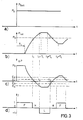
- Fig. 1 is a wheel brake cylinder with 2, a 3-position three-way solenoid valve, with 3 a pressure source, with 4 a pressure sensor, with 5 a control device, with 6 a brake pedal and with 7 a setpoint sensor which can be actuated by the pedal 6 and which is one of the Position of the pedal provides an electrical signal.
- the setpoint pressure value P setpoint is compared in the control device 5 with the actual pressure measured by the transmitter 4. Depending on whether the difference AP of these pressure signals deviate from one another by a predetermined small value in one or the other direction, one or the other winding of the 3/3 solenoid valve is actuated by the control device 5 and thus either the pressure in the wheel brake cylinder 1 is increased. (when the pressure source 3 is turned on), or decreased when an outlet 8 is connected to the wheel brake cylinder. Air is assumed here as a pressure medium. In the valve position without activation, the pressure remains constant.
- Fig. 2 shows the associated control loop.
- a three-point controller with 21 and a controlled system, which comprises the valve (21a) and the lines and the brake cylinder (21b) with 21.
- the sensor measuring the pressure in the brake cylinder is designated by 22.
- the three-point controller 21 has different switching thresholds for the generation (E 2 and E 4 ) of the switching signals or their disappearance (E, and E,) both for the pressure build-up and for the pressure reduction (hysteresis).
- FIG. 3 A setpoint signal P o is shown as a jump in FIG. 3a.
- 2b shows the actual pressure curve P ist . It can be seen that the pressure build-up is delayed by the time T L - due to the valve properties (dead times) and the system itself (lines, brake cylinders, etc.)
- Fig. 2c) shows the course of the difference AP and Fig. 2d the output signals y of the controller, which are supplied to the solenoid valve 2 and 21 a.
- FIG. 4 shows the braking system in a somewhat different implementation than FIG. 1 and for the brakes 40a and 40b of an axle;
- the setpoint generator bears the reference number 41, the control device reference number 42, the pressure source reference number 43 and a 2/2-filling solenoid valve reference number 44.
- Control valves 45a and 45b and rotational speed sensors 47a and 47b are assigned to the two brakes or their wheels.
- An axle load sensor 48 is also provided.
- the valves 45a and 45b can also be used to regulate the pressure individually on a wheel-by-wheel basis when supply pressure is present at the inputs of the valve 44.
- the rotational speed sensors 47a and 47b, the valves 45a and 45b and possibly also the pressure sensors 46a and 46b and part of the control device 42 also form an anti-lock control system.
- the valves 45a and 45b are three-position valves.
- the pressure sensors 46a and 46b can also be used for slip control in the ABS case.
- the three-position valve 2 of FIG. 1 is simulated here by the valve 44 and the valves 45a and 45b.
- pressure is applied to the brakes 40a and 40b, and by actuating the valves 45a and 45b to the dismantling position, pressure is reduced.
- the pressure holding function is ensured by the valve 44 in its basic position.
- the valves 45a and 45b take over all functions.
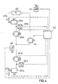
- Fig. 5 shows the control loop of an embodiment of the invention.
- the predetermined target pressure from the setpoint adjuster P target is weighted in block 50 in accordance with the axle load.
- the difference is fed to a three-point controller 52, which corresponds to the controller 21 described in connection with FIG. 2, with the exception that it has switchable thresholds E to E.
- the output signal y * of the controller 52 is supplied to blocks 53 and 54.
- the output signal y of block 53 reaches the solenoid valve arrangement (for example 44, 45a and 45b of FIG. 4), which is shown here as block 55a in a block 55.
- This block 55 also includes the controlled system line and brake cylinder as block 55b.
- a pressure sensor 56 supplies a signal proportional to the actual pressure in the brake cylinder to the difference generator 51.
- the different functions of the control device in the working areas / ⁇ P /> ⁇ P G (normal operation) and / ⁇ P / ⁇ AP G (pulse operation) are effected by the blocks 52-54 .
- block 54 In order to distinguish the areas from one another, block 54 requires information about the size of AP, for which purpose the sizes P target and P actual are supplied. Block 54 switches the operation of block 53 when the threshold ⁇ P G is reached.
- the block 53 While in the normal control range the control signals y * generated by the controller 52 pass through the block 53 unchanged and control the valve arrangement 55a, in the pulse range the block 53, as long as y * is present, emits pulsed control signals for the valve device, the length T E of the control pulses for both the pressure build-up as well as for the pressure reduction are variable and depend on different parameters. The subsequent pulse breaks T BER are also variable and serve to calm the system.
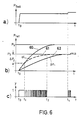
- FIG. 6 The mode of operation is shown in FIG. 6.
- the target value P target is plotted there in FIG. 6a (brake pressure is to be applied).
- Fig. 6b shows the pressure curve 60 that can be achieved at a supply pressure P v by opening the valve 44 or 55a, the pressure curve 61 achieved by the brake control according to the invention with normal control mode and pulse mode and the pressure curve 62 that can be achieved by pneumatic specification P o .
- the Pressure in normal control mode (t o -t,) in the controller according to the invention curve 61
- the control signals y for the valve are shown in FIG. 6c.
- FIG. 7 shows the control cycles in a representation in which / AP / is plotted over the time t and in relation to a constant time T A (sampling time of the computer).
- the normal control range is above the value ⁇ P G.
- the pulse control range is located between AP G and 0, which is further divided into two partial ranges 0 to ⁇ P F (fine control range) and ⁇ P F to ⁇ P G (rough control range).
- the fact that / AP / is plotted means that the approximation to the setpoint shown applies to both pressure increase and pressure decrease. No pressure maintenance phases are visible in the diagram, because pressure equalization processes are still going on in the T BER phases.
- Fig. 7 shows that the control of the valve in the normal range with a continuous signal at time 1 leads to the rough range limit ⁇ P G.
- Block 54 then triggers a switch to pulse mode by block 53.
- predetermined values T o and T BER are stored for times T E and T BER , which together form Tx o (see FIG. 7 above) used.
- Tx are calculated according to the following laws:
- the pulse time T E is therefore dependent on the previous T E and AT E.
- ⁇ T E depends on the sub-range in which the control is running ( ⁇ P i ), but also on the size of the target pressure P Soll and the number (n) of the pulses that have already occurred in the respective sub-range.
- AT E is calculated, for example, from: f (n) is preferably n.
- the target pressure is divided into 10 ranges and, as assumed in FIG. 7, the pressure difference Ap from 0 to ⁇ P G into two ranges and, accordingly, 20 values for ⁇ P '( ⁇ P i ; P target ) for the pressure build-up and reduction. and T o and a non-volatile memory are stored and used to calculate T E.
- the shortening is therefore dependent on the previously valid ⁇ T ', but also on a value a, which in turn depends on ⁇ P i , that is to say on the subrange, and on the value ⁇ P * by which the 0 line was exceeded.
- the controller is designed in such a way that it assigns a bandwidth P Soll ⁇ ⁇ P to a predetermined target pressure value P Soll and subsequently maintains this value for P Soll as long as this bandwidth is not left. This is shown in FIG. 8, in which the fluctuating P setpoint values are recorded and the P setpoint values evaluated by the controller are given below. So that a pressure actual value change can be clearly assigned to a specific Tx pulse, the pressure setpoint must be constant, or may only be within the range ⁇ ⁇ P.
- the TX pulses are only optimized if the setpoint does not leave the bandwidth Pset ⁇ ⁇ P during the entire pulse time (T E + T BER ) of the previous pulse.
- the bandwidth limit ⁇ ⁇ P for the setpoint value of the pressure becomes zero, so that from time t 3 the pressure setpoint is used directly by the driver as the setpoint value for the pressure regulator. As soon as Y " ⁇ O (time 4), the bandwidth values ⁇ ⁇ P are placed around the driver's pressure setpoint.
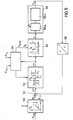
- FIG. 9 shows a further embodiment of the controller 52 of FIG. 5, as it can be used in the general control area, but can also be used completely independently of the use of normal and pulse control areas.
- a controlled system 90 which is measured in the transmitter 91 and fed to a differential stage 92 to form ⁇ P
- an additional feedback 93 is provided here via the controller 94, which practically forms a reserve for the controller.
- FIG. 10 where the target pressure value P o is reproduced in Fig. 10a and FIG. 10b of the process value P is in consideration of the delay time T L.
- 10c shows the switching signal y output by the controller 94.
- This switching signal is influenced by the feedback signal x, the feedback 93 by means of the differential element 95 (see FIG. 10d), which increases from 0 to t, and thus already in the time T L , in which ⁇ P is constant (see FIG. 10e), the input signal x 2 of the controller is reduced (see FIG. 10f).
- the time T L the influences of ⁇ P and x 1 overlap, so that t falls below E already at t.
- the lead given by the signal x already leads very close to the target value P target in a control game .
- the return 94 must be adapted to the circumstances.
- the primary goal is to achieve the desired pressure setpoint with as few switching signals as possible. With optimal adjustment, this would succeed in one switching cycle.
- the adequately dimensioned calming times ensure that equalization processes are completed at the end so that the pressure now present can be measured correctly.
- the non-linearities and other influences in the system are taken into account by the changes in the parameters depending on the setpoint and the ⁇ P range.
- An intermediate range .DELTA.P G ⁇ .DELTA.P ⁇ .DELTA.P A is advantageously introduced between the normal control range and the coarse control range when the actual pressure builds up (P target > P actual ).
- ⁇ P A is reached, the valve is switched off at time t o . After a calming time has elapsed, the control deviation ⁇ P is measured at time t.
- the switch-off threshold ⁇ P A is changed as follows for subsequent braking: ⁇ P is the positive as well as the negative measured value of the control deviation.
- ⁇ P is brought into the range 0 ⁇ AP ⁇ P G with relatively large variable Tx pulses.
- the described cases of the ⁇ P A optimization are shown in FIGS. 11 a and 11 b.
- ⁇ P A can also be adjusted in a controlled manner, for example depending on the on-board voltage or the supply pressure.
- the fine control range 0 ⁇ ⁇ P ⁇ ⁇ P F can be subdivided again into ranges ⁇ P F ⁇ ⁇ p ⁇ ⁇ P F and 0 ⁇ ⁇ P ⁇ ⁇ P F.
- the same rules are also used for the 0 neighboring area with possibly different output values as described in accordance with FIG. 7, however, for example, a change in T E is only carried out after every two pulses.
- the initial pulses for valve actuation in the range ⁇ P ⁇ ⁇ P G are advantageously chosen to be so small that the valve is just not yet actuated by them.
- the pressure sensor detects when the valve has responded and an air packet has passed.
- the system finds the time value that is necessary for the shortest activation of the valve and can save this or a modified time value for later activation.
- the controller can determine the optimal values without special adaptation to the system and save them for use in further braking.
- the controller is therefore adaptive and can adapt itself to any braking system.
- a microprocessor is advantageously used to carry out this regulation.
Landscapes
- Engineering & Computer Science (AREA)
- Transportation (AREA)
- Mechanical Engineering (AREA)
- Physics & Mathematics (AREA)
- Electromagnetism (AREA)
- Fluid Mechanics (AREA)
- Regulating Braking Force (AREA)
Applications Claiming Priority (2)
| Application Number | Priority Date | Filing Date | Title |
|---|---|---|---|
| DE3543145 | 1985-12-06 | ||
| DE3543145A DE3543145C2 (de) | 1985-12-06 | 1985-12-06 | Elektrisches Bremssystem für ein Fahrzeug |
Publications (4)
| Publication Number | Publication Date |
|---|---|
| EP0224832A2 true EP0224832A2 (fr) | 1987-06-10 |
| EP0224832A3 EP0224832A3 (en) | 1988-08-24 |
| EP0224832B1 EP0224832B1 (fr) | 1990-02-07 |
| EP0224832B2 EP0224832B2 (fr) | 1995-09-27 |
Family
ID=6287792
Family Applications (1)
| Application Number | Title | Priority Date | Filing Date |
|---|---|---|---|
| EP86116256A Expired - Lifetime EP0224832B2 (fr) | 1985-12-06 | 1986-11-24 | Système de freinage électrique pour un véhicule |
Country Status (4)
| Country | Link |
|---|---|
| US (1) | US4805105A (fr) |
| EP (1) | EP0224832B2 (fr) |
| JP (1) | JP2650187B2 (fr) |
| DE (2) | DE3543145C2 (fr) |
Cited By (3)
| Publication number | Priority date | Publication date | Assignee | Title |
|---|---|---|---|---|
| GB2224322A (en) * | 1988-10-03 | 1990-05-02 | American Standard Inc | Brake control system |
| US5251966A (en) * | 1989-11-04 | 1993-10-12 | Wabco Westinghouse Fahrzeugbremsen Gmbh | Tractor and trailer braking control system to prevent trailer overrun |
| EP1028043A3 (fr) * | 1999-02-11 | 2003-04-02 | WABCO GmbH & CO. OHG | Dispositif de commande de pression hydraulique |
Families Citing this family (32)
| Publication number | Priority date | Publication date | Assignee | Title |
|---|---|---|---|---|
| DE3731076A1 (de) * | 1987-09-16 | 1989-03-30 | Bosch Gmbh Robert | Verfahren zur umsetzung eines einem solldruck entsprechenden signals |
| DE3903585A1 (de) * | 1989-02-07 | 1990-08-09 | Knorr Bremse Ag | Blockiergeschuetzte bremsanlage mit giermomentbegrenzung |
| US5050940A (en) * | 1990-02-05 | 1991-09-24 | Allied-Signal Inc. | Brake control and anti-skid system |
| US5127495A (en) * | 1990-09-28 | 1992-07-07 | Allied-Signal Inc. | Parking brake and method therefor |
| US5148894A (en) * | 1990-10-11 | 1992-09-22 | Allied-Signal Inc. | Disk brake/parking brake with threaded piston rod and motor |
| US5222787A (en) * | 1990-11-20 | 1993-06-29 | Allied-Signal Inc. | Electro-hydraulic braking system |
| US5636910A (en) * | 1992-09-10 | 1997-06-10 | Robert Bosch Gmbh | System and method for controlling the dynamics of vehicle movement |
| JPH07172286A (ja) * | 1993-03-09 | 1995-07-11 | Toyota Motor Corp | アンチロック制御装置 |
| US5732379A (en) * | 1994-11-25 | 1998-03-24 | Itt Automotive Europe Gmbh | Brake system for a motor vehicle with yaw moment control |
| US5774821A (en) * | 1994-11-25 | 1998-06-30 | Itt Automotive Europe Gmbh | System for driving stability control |
| US5710704A (en) * | 1994-11-25 | 1998-01-20 | Itt Automotive Europe Gmbh | System for driving stability control during travel through a curve |
| DE19515050A1 (de) * | 1994-11-25 | 1996-05-30 | Teves Gmbh Alfred | Verfahren zur Fahrstabilitätsregelschaltung mit Steuerung über Druckgradienten |
| US5694321A (en) * | 1994-11-25 | 1997-12-02 | Itt Automotive Europe Gmbh | System for integrated driving stability control |
| US5710705A (en) * | 1994-11-25 | 1998-01-20 | Itt Automotive Europe Gmbh | Method for determining an additional yawing moment based on side slip angle velocity |
| US5742507A (en) * | 1994-11-25 | 1998-04-21 | Itt Automotive Europe Gmbh | Driving stability control circuit with speed-dependent change of the vehicle model |
| US5732377A (en) * | 1994-11-25 | 1998-03-24 | Itt Automotive Europe Gmbh | Process for controlling driving stability with a yaw rate sensor equipped with two lateral acceleration meters |
| US5711024A (en) * | 1994-11-25 | 1998-01-20 | Itt Automotive Europe Gmbh | System for controlling yaw moment based on an estimated coefficient of friction |
| US5732378A (en) * | 1994-11-25 | 1998-03-24 | Itt Automotive Europe Gmbh | Method for determining a wheel brake pressure |
| US5701248A (en) * | 1994-11-25 | 1997-12-23 | Itt Automotive Europe Gmbh | Process for controlling the driving stability with the king pin inclination difference as the controlled variable |
| DE4442326B4 (de) * | 1994-11-29 | 2004-01-29 | Robert Bosch Gmbh | Verfahren und Vorrichtung zur Ermittlung einer Druckgröße |
| EP0786389B1 (fr) * | 1996-01-23 | 2002-06-12 | WABCO GmbH & Co. OHG | Procédé pour la remise sous pression pour un véhicule équipé d'un système d'anti-blocage |
| DE19707960B4 (de) * | 1997-02-27 | 2011-02-17 | Robert Bosch Gmbh | Verfahren und Vorrichtung zur Regelung des Drucks in wenigstens einer Radbremse |
| DE69836301T2 (de) | 1997-07-29 | 2007-06-06 | Toyota Jidosha Kabushiki Kaisha, Toyota | Elektrisch betätigte Bremsanlage mit Betätigungsvorrichtung eines elektrischen Bremsmotors zur Erlangung einer Beziehung zwischen Motorkraft und Bremsmoment |
| DE19804570C2 (de) * | 1998-02-05 | 2003-02-06 | Knorr Bremse Systeme | Bremssteuerung für Fahrzeuge, insbesondere für Schienenfahrzeuge und Verfahren zum Steuern von Fahrzeugbremsen |
| DE10021135B4 (de) * | 2000-04-29 | 2007-08-30 | Bayerische Motoren Werke Ag | Verfahren und Vorrichtung zur Regelung einer vorgegebenen Soll-Verzögerung eines Kraftfahrzeugs |
| EP1296865B1 (fr) * | 2000-06-20 | 2004-09-08 | Continental Teves AG & Co. oHG | Procede et systeme asservi de commande d'un systeme de freinage a regulation electronique |
| DE10156815A1 (de) * | 2001-11-20 | 2003-06-05 | Lucas Automotive Gmbh | Verfahren und System zur Steuerung einer Bremsausrüstung |
| CN102481909B (zh) * | 2009-09-04 | 2015-03-11 | 博世株式会社 | 车辆的制动控制装置及方法 |
| DE102013016877B3 (de) * | 2013-10-11 | 2014-10-09 | Knorr-Bremse Systeme für Nutzfahrzeuge GmbH | Verfahren zum Steuern einer Drucksteuervorrichtung einer Druckmittel-Bremsanlage eines Fahrzeugs |
| JP2016179794A (ja) * | 2015-03-25 | 2016-10-13 | ローベルト ボッシュ ゲゼルシャフト ミット ベシュレンクテル ハフツング | 液圧装置及び液圧装置の制御方法 |
| CN105644543B (zh) * | 2016-02-04 | 2018-06-01 | 西安航空制动科技有限公司 | 一种刹车系统刹车压力校正方法 |
| EP4172030A4 (fr) * | 2020-06-24 | 2024-07-10 | Ree Automotive Ltd. | Systèmes de freinage intégrés dans des modules de coin de véhicule et leurs procédés d'utilisation |
Citations (2)
| Publication number | Priority date | Publication date | Assignee | Title |
|---|---|---|---|---|
| DE2128169A1 (de) | 1971-06-07 | 1972-12-14 | Teldix Gmbh | Bremssystem für ein Fahrzeug |
| DE2327508A1 (de) | 1973-05-30 | 1974-12-19 | Teldix Gmbh | Fahrzeugbremsanlage |
Family Cites Families (13)
| Publication number | Priority date | Publication date | Assignee | Title |
|---|---|---|---|---|
| JPS6037321B2 (ja) * | 1974-11-30 | 1985-08-26 | 株式会社豊田中央研究所 | 流体アクチユエ−タの制御装置 |
| FR2358303A1 (fr) * | 1976-07-16 | 1978-02-10 | Knorr Bremse Gmbh | Circuit de regulation electropneumatique pour la force de freinage de vehicules, plus particulierement de vehicules sur rails |
| DE2830580A1 (de) * | 1978-07-12 | 1980-02-28 | Wabco Fahrzeugbremsen Gmbh | Verfahren und einrichtung zur regelung des bremsdruckes in blockiergeschuetzten fahrzeugbremsanlagen |
| US4370714A (en) * | 1980-08-25 | 1983-01-25 | Minnesota Automotive, Inc. | Electronically actuated brake system |
| DE3039512A1 (de) * | 1980-10-20 | 1982-05-06 | Knorr-Bremse GmbH, 8000 München | Blockiergeschuetzter bremskraftrgelkreis |
| DE3138647A1 (de) * | 1981-09-29 | 1983-04-14 | Dr.Ing.H.C. F. Porsche Ag, 7000 Stuttgart | "steuervorrichtung fuer magnetventile" |
| DE3209369A1 (de) * | 1982-03-15 | 1983-09-22 | Robert Bosch Gmbh, 7000 Stuttgart | Antiblockierregelsystem |
| JPS59136533A (ja) * | 1983-01-27 | 1984-08-06 | Honda Motor Co Ltd | オートクルーズ制御装置 |
| GB2135745B (en) * | 1983-02-26 | 1987-01-07 | Bosch Gmbh Robert | Circuit for controlling the brake pressure in anti-lock vehicle brake systems |
| JPS59192705U (ja) * | 1983-06-06 | 1984-12-21 | 株式会社明電舎 | 偏差比例制御装置 |
| JPS6038246A (ja) * | 1983-08-11 | 1985-02-27 | Nissan Motor Co Ltd | アンチスキッド制御装置 |
| JPS60128054A (ja) * | 1983-12-13 | 1985-07-08 | Nissan Motor Co Ltd | アンチスキッド制御装置 |
| DE3502276A1 (de) * | 1985-01-24 | 1986-07-24 | Wabco Westinghouse Fahrzeugbremsen GmbH, 3000 Hannover | Einrichtung zur stetigen steuerung eines normalerweise fuer unstetige betriebsweise ausgebildeten magnetventiles |
-
1985
- 1985-12-06 DE DE3543145A patent/DE3543145C2/de not_active Expired - Fee Related
-
1986
- 1986-11-24 EP EP86116256A patent/EP0224832B2/fr not_active Expired - Lifetime
- 1986-11-24 DE DE8686116256T patent/DE3668857D1/de not_active Expired - Lifetime
- 1986-12-04 US US06/938,024 patent/US4805105A/en not_active Expired - Fee Related
- 1986-12-05 JP JP61289123A patent/JP2650187B2/ja not_active Expired - Fee Related
Patent Citations (2)
| Publication number | Priority date | Publication date | Assignee | Title |
|---|---|---|---|---|
| DE2128169A1 (de) | 1971-06-07 | 1972-12-14 | Teldix Gmbh | Bremssystem für ein Fahrzeug |
| DE2327508A1 (de) | 1973-05-30 | 1974-12-19 | Teldix Gmbh | Fahrzeugbremsanlage |
Cited By (6)
| Publication number | Priority date | Publication date | Assignee | Title |
|---|---|---|---|---|
| GB2224322A (en) * | 1988-10-03 | 1990-05-02 | American Standard Inc | Brake control system |
| AU620442B2 (en) * | 1988-10-03 | 1992-02-20 | American Standard, Inc. | Digital air brake control system |
| GB2224322B (en) * | 1988-10-03 | 1993-04-28 | American Standard Inc | Brake control system |
| AU649535B2 (en) * | 1988-10-03 | 1994-05-26 | American Standard, Inc. | Digital air brake control system |
| US5251966A (en) * | 1989-11-04 | 1993-10-12 | Wabco Westinghouse Fahrzeugbremsen Gmbh | Tractor and trailer braking control system to prevent trailer overrun |
| EP1028043A3 (fr) * | 1999-02-11 | 2003-04-02 | WABCO GmbH & CO. OHG | Dispositif de commande de pression hydraulique |
Also Published As
| Publication number | Publication date |
|---|---|
| DE3543145A1 (de) | 1987-06-11 |
| EP0224832B1 (fr) | 1990-02-07 |
| EP0224832A3 (en) | 1988-08-24 |
| JP2650187B2 (ja) | 1997-09-03 |
| EP0224832B2 (fr) | 1995-09-27 |
| DE3543145C2 (de) | 1995-08-03 |
| US4805105A (en) | 1989-02-14 |
| JPS62134363A (ja) | 1987-06-17 |
| DE3668857D1 (de) | 1990-03-15 |
Similar Documents
| Publication | Publication Date | Title |
|---|---|---|
| DE3543145C2 (de) | Elektrisches Bremssystem für ein Fahrzeug | |
| EP0365604B1 (fr) | Regulateur du glissement de freinage | |
| DE19616732B4 (de) | Verfahren und Vorrichtung zur Steuerung der Bremsanlage eines Fahrzeugs | |
| EP0307588B1 (fr) | Système anti-blockage pour véhicules | |
| EP0813481B1 (fr) | Systeme de regulation de la pression de freinage | |
| EP0122570A2 (fr) | Système de régulation antiblocage | |
| DE4428929A1 (de) | Verfahren und Einrichtung zur Druckregelung | |
| DE19920096B4 (de) | Vorrichtung zur Bremslichtansteuerung | |
| DE2757911A1 (de) | Blockierschutz-regeleinrichtung | |
| DE3621164C2 (fr) | ||
| EP3354527A1 (fr) | Procédé de réglage de pression de freinage d'un véhicule à l'aide de la commande d'une soupape de réglage de pression, installation de freinage permettant la mise en uvre dudit procédé ainsi que véhicule à moteur | |
| DE10201160A1 (de) | Verfahren und Vorrichtung zur Steuerung der Fahrgeschwindigkeit eines Fahrzeugs | |
| DE19848960B4 (de) | Verfahren und Vorrichtung zur Steuerung eines Drucksteuerventils, insbesondere einer Bremsanlage | |
| EP3612421B1 (fr) | Methode pour determiner les prametres de commutation des soupapes a solenoide d'un systeme de freinage | |
| DE4214547C2 (de) | Fahrzeugbremssystem | |
| DE4021993C2 (de) | Bremsdruck-Steuersystem für Kraftfahrzeuge | |
| DE1755615C3 (de) | Antiblockierregelsystem | |
| EP3847062B1 (fr) | Structure de régulateur distribuée pour obtenir des propriétés de régulateur optimisées et une durée de vie de soupape accrue | |
| DE2826295C2 (fr) | ||
| DE10047761A1 (de) | Verfahren und Vorrichtung zur Steuerung einer Radbremse eines Fahrzeugs | |
| DE19524885A1 (de) | Antiblockiersystem für Fahrzeuge | |
| DE1924565A1 (de) | Antiblockierregelsystem | |
| DE3607329C2 (fr) | ||
| EP0346592A1 (fr) | Dispositif de régulation du glissement de traction et de limitation de vitesse | |
| EP1021329B1 (fr) | Servofrein |
Legal Events
| Date | Code | Title | Description |
|---|---|---|---|
| PUAI | Public reference made under article 153(3) epc to a published international application that has entered the european phase |
Free format text: ORIGINAL CODE: 0009012 |
|
| AK | Designated contracting states |
Kind code of ref document: A2 Designated state(s): DE FR GB IT SE |
|
| PUAL | Search report despatched |
Free format text: ORIGINAL CODE: 0009013 |
|
| AK | Designated contracting states |
Kind code of ref document: A3 Designated state(s): DE FR GB IT SE |
|
| 17P | Request for examination filed |
Effective date: 19880926 |
|
| 17Q | First examination report despatched |
Effective date: 19890214 |
|
| GRAA | (expected) grant |
Free format text: ORIGINAL CODE: 0009210 |
|
| AK | Designated contracting states |
Kind code of ref document: B1 Designated state(s): DE FR GB IT SE |
|
| PG25 | Lapsed in a contracting state [announced via postgrant information from national office to epo] |
Ref country code: GB Effective date: 19900207 |
|
| REF | Corresponds to: |
Ref document number: 3668857 Country of ref document: DE Date of ref document: 19900315 |
|
| GBT | Gb: translation of ep patent filed (gb section 77(6)(a)/1977) | ||
| ET | Fr: translation filed | ||
| ITF | It: translation for a ep patent filed | ||
| PLBI | Opposition filed |
Free format text: ORIGINAL CODE: 0009260 |
|
| 26 | Opposition filed |
Opponent name: WABCO WESTINGHOUSE FAHRZEUGBREMSEN GMBH Effective date: 19901103 |
|
| ITTA | It: last paid annual fee | ||
| RAP4 | Party data changed (patent owner data changed or rights of a patent transferred) |
Owner name: ROBERT BOSCH GMBH |
|
| PLAB | Opposition data, opponent's data or that of the opponent's representative modified |
Free format text: ORIGINAL CODE: 0009299OPPO |
|
| R26 | Opposition filed (corrected) |
Opponent name: WABCO VERMOEGENSVERWALTUNGS GMBH Effective date: 19901103 |
|
| PGFP | Annual fee paid to national office [announced via postgrant information from national office to epo] |
Ref country code: GB Payment date: 19941115 Year of fee payment: 9 |
|
| PGFP | Annual fee paid to national office [announced via postgrant information from national office to epo] |
Ref country code: SE Payment date: 19941122 Year of fee payment: 9 |
|
| EAL | Se: european patent in force in sweden |
Ref document number: 86116256.8 |
|
| PLAB | Opposition data, opponent's data or that of the opponent's representative modified |
Free format text: ORIGINAL CODE: 0009299OPPO |
|
| R26 | Opposition filed (corrected) |
Opponent name: WABCO GMBH Effective date: 19901103 |
|
| PUAH | Patent maintained in amended form |
Free format text: ORIGINAL CODE: 0009272 |
|
| STAA | Information on the status of an ep patent application or granted ep patent |
Free format text: STATUS: PATENT MAINTAINED AS AMENDED |
|
| 27A | Patent maintained in amended form |
Effective date: 19950927 |
|
| AK | Designated contracting states |
Kind code of ref document: B2 Designated state(s): DE FR GB IT SE |
|
| PG25 | Lapsed in a contracting state [announced via postgrant information from national office to epo] |
Ref country code: SE Effective date: 19951125 |
|
| ET3 | Fr: translation filed ** decision concerning opposition | ||
| ITF | It: translation for a ep patent filed | ||
| GBV | Gb: ep patent (uk) treated as always having been void in accordance with gb section 77(7)/1977 [no translation filed] |
Effective date: 19900207 |
|
| EUG | Se: european patent has lapsed |
Ref document number: 86116256.8 |
|
| APAC | Appeal dossier modified |
Free format text: ORIGINAL CODE: EPIDOS NOAPO |
|
| APAC | Appeal dossier modified |
Free format text: ORIGINAL CODE: EPIDOS NOAPO |
|
| PGFP | Annual fee paid to national office [announced via postgrant information from national office to epo] |
Ref country code: FR Payment date: 19991123 Year of fee payment: 14 |
|
| PG25 | Lapsed in a contracting state [announced via postgrant information from national office to epo] |
Ref country code: FR Free format text: LAPSE BECAUSE OF NON-PAYMENT OF DUE FEES Effective date: 20010731 |
|
| REG | Reference to a national code |
Ref country code: FR Ref legal event code: ST |
|
| PGFP | Annual fee paid to national office [announced via postgrant information from national office to epo] |
Ref country code: DE Payment date: 20021216 Year of fee payment: 17 |
|
| PG25 | Lapsed in a contracting state [announced via postgrant information from national office to epo] |
Ref country code: DE Free format text: LAPSE BECAUSE OF NON-PAYMENT OF DUE FEES Effective date: 20040602 |
|
| APAH | Appeal reference modified |
Free format text: ORIGINAL CODE: EPIDOSCREFNO |
|
| PG25 | Lapsed in a contracting state [announced via postgrant information from national office to epo] |
Ref country code: IT Free format text: LAPSE BECAUSE OF NON-PAYMENT OF DUE FEES;WARNING: LAPSES OF ITALIAN PATENTS WITH EFFECTIVE DATE BEFORE 2007 MAY HAVE OCCURRED AT ANY TIME BEFORE 2007. THE CORRECT EFFECTIVE DATE MAY BE DIFFERENT FROM THE ONE RECORDED. Effective date: 20051124 |