EP0224878A2 - Machine pour la compression et le transport de fluides - Google Patents
Machine pour la compression et le transport de fluides Download PDFInfo
- Publication number
- EP0224878A2 EP0224878A2 EP86116496A EP86116496A EP0224878A2 EP 0224878 A2 EP0224878 A2 EP 0224878A2 EP 86116496 A EP86116496 A EP 86116496A EP 86116496 A EP86116496 A EP 86116496A EP 0224878 A2 EP0224878 A2 EP 0224878A2
- Authority
- EP
- European Patent Office
- Prior art keywords
- piston
- ring
- bearing
- rolling ring
- machine according
- Prior art date
- Legal status (The legal status is an assumption and is not a legal conclusion. Google has not performed a legal analysis and makes no representation as to the accuracy of the status listed.)
- Withdrawn
Links
- 239000012530 fluid Substances 0.000 title claims abstract description 10
- 230000006835 compression Effects 0.000 title claims description 26
- 238000007906 compression Methods 0.000 title claims description 26
- 238000005096 rolling process Methods 0.000 claims abstract description 69
- 238000000034 method Methods 0.000 claims description 3
- 230000036316 preload Effects 0.000 claims description 3
- 230000008569 process Effects 0.000 claims description 3
- 230000009471 action Effects 0.000 claims description 2
- 238000006073 displacement reaction Methods 0.000 claims description 2
- 230000002093 peripheral effect Effects 0.000 claims description 2
- 238000004073 vulcanization Methods 0.000 claims 1
- 230000007246 mechanism Effects 0.000 description 8
- 238000001816 cooling Methods 0.000 description 5
- 230000017525 heat dissipation Effects 0.000 description 5
- 238000007789 sealing Methods 0.000 description 5
- 238000002347 injection Methods 0.000 description 4
- 239000007924 injection Substances 0.000 description 4
- 238000004519 manufacturing process Methods 0.000 description 3
- 238000010073 coating (rubber) Methods 0.000 description 2
- 238000005461 lubrication Methods 0.000 description 2
- 230000010349 pulsation Effects 0.000 description 2
- 230000009467 reduction Effects 0.000 description 2
- OKTJSMMVPCPJKN-UHFFFAOYSA-N Carbon Chemical compound [C] OKTJSMMVPCPJKN-UHFFFAOYSA-N 0.000 description 1
- 230000008901 benefit Effects 0.000 description 1
- 229910052799 carbon Inorganic materials 0.000 description 1
- 238000005056 compaction Methods 0.000 description 1
- 238000010276 construction Methods 0.000 description 1
- 230000000694 effects Effects 0.000 description 1
- 230000002349 favourable effect Effects 0.000 description 1
- 239000007788 liquid Substances 0.000 description 1
- -1 polytetrafluoroethylene Polymers 0.000 description 1
- 229920001343 polytetrafluoroethylene Polymers 0.000 description 1
- 239000004810 polytetrafluoroethylene Substances 0.000 description 1
- 238000000926 separation method Methods 0.000 description 1
- 239000007787 solid Substances 0.000 description 1
- 238000003860 storage Methods 0.000 description 1
Images


Classifications
-
- F—MECHANICAL ENGINEERING; LIGHTING; HEATING; WEAPONS; BLASTING
- F16—ENGINEERING ELEMENTS AND UNITS; GENERAL MEASURES FOR PRODUCING AND MAINTAINING EFFECTIVE FUNCTIONING OF MACHINES OR INSTALLATIONS; THERMAL INSULATION IN GENERAL
- F16C—SHAFTS; FLEXIBLE SHAFTS; ELEMENTS OR CRANKSHAFT MECHANISMS; ROTARY BODIES OTHER THAN GEARING ELEMENTS; BEARINGS
- F16C35/00—Rigid support of bearing units; Housings, e.g. caps, covers
- F16C35/04—Rigid support of bearing units; Housings, e.g. caps, covers in the case of ball or roller bearings
- F16C35/06—Mounting or dismounting of ball or roller bearings; Fixing them onto shaft or in housing
- F16C35/07—Fixing them on the shaft or housing with interposition of an element
- F16C35/073—Fixing them on the shaft or housing with interposition of an element between shaft and inner race ring
-
- F—MECHANICAL ENGINEERING; LIGHTING; HEATING; WEAPONS; BLASTING
- F01—MACHINES OR ENGINES IN GENERAL; ENGINE PLANTS IN GENERAL; STEAM ENGINES
- F01C—ROTARY-PISTON OR OSCILLATING-PISTON MACHINES OR ENGINES
- F01C1/00—Rotary-piston machines or engines
- F01C1/30—Rotary-piston machines or engines having the characteristics covered by two or more groups F01C1/02, F01C1/08, F01C1/22, F01C1/24 or having the characteristics covered by one of these groups together with some other type of movement between co-operating members
- F01C1/34—Rotary-piston machines or engines having the characteristics covered by two or more groups F01C1/02, F01C1/08, F01C1/22, F01C1/24 or having the characteristics covered by one of these groups together with some other type of movement between co-operating members having the movement defined in group F01C1/08 or F01C1/22 and relative reciprocation between the co-operating members
- F01C1/344—Rotary-piston machines or engines having the characteristics covered by two or more groups F01C1/02, F01C1/08, F01C1/22, F01C1/24 or having the characteristics covered by one of these groups together with some other type of movement between co-operating members having the movement defined in group F01C1/08 or F01C1/22 and relative reciprocation between the co-operating members with vanes reciprocating with respect to the inner member
- F01C1/348—Rotary-piston machines or engines having the characteristics covered by two or more groups F01C1/02, F01C1/08, F01C1/22, F01C1/24 or having the characteristics covered by one of these groups together with some other type of movement between co-operating members having the movement defined in group F01C1/08 or F01C1/22 and relative reciprocation between the co-operating members with vanes reciprocating with respect to the inner member the vanes positively engaging, with circumferential play, an outer rotatable member
-
- F—MECHANICAL ENGINEERING; LIGHTING; HEATING; WEAPONS; BLASTING
- F16—ENGINEERING ELEMENTS AND UNITS; GENERAL MEASURES FOR PRODUCING AND MAINTAINING EFFECTIVE FUNCTIONING OF MACHINES OR INSTALLATIONS; THERMAL INSULATION IN GENERAL
- F16C—SHAFTS; FLEXIBLE SHAFTS; ELEMENTS OR CRANKSHAFT MECHANISMS; ROTARY BODIES OTHER THAN GEARING ELEMENTS; BEARINGS
- F16C19/00—Bearings with rolling contact, for exclusively rotary movement
- F16C19/22—Bearings with rolling contact, for exclusively rotary movement with bearing rollers essentially of the same size in one or more circular rows, e.g. needle bearings
-
- F—MECHANICAL ENGINEERING; LIGHTING; HEATING; WEAPONS; BLASTING
- F16—ENGINEERING ELEMENTS AND UNITS; GENERAL MEASURES FOR PRODUCING AND MAINTAINING EFFECTIVE FUNCTIONING OF MACHINES OR INSTALLATIONS; THERMAL INSULATION IN GENERAL
- F16C—SHAFTS; FLEXIBLE SHAFTS; ELEMENTS OR CRANKSHAFT MECHANISMS; ROTARY BODIES OTHER THAN GEARING ELEMENTS; BEARINGS
- F16C19/00—Bearings with rolling contact, for exclusively rotary movement
- F16C19/22—Bearings with rolling contact, for exclusively rotary movement with bearing rollers essentially of the same size in one or more circular rows, e.g. needle bearings
- F16C19/34—Bearings with rolling contact, for exclusively rotary movement with bearing rollers essentially of the same size in one or more circular rows, e.g. needle bearings for both radial and axial load
- F16C19/36—Bearings with rolling contact, for exclusively rotary movement with bearing rollers essentially of the same size in one or more circular rows, e.g. needle bearings for both radial and axial load with a single row of rollers
- F16C19/361—Bearings with rolling contact, for exclusively rotary movement with bearing rollers essentially of the same size in one or more circular rows, e.g. needle bearings for both radial and axial load with a single row of rollers with cylindrical rollers
- F16C19/362—Bearings with rolling contact, for exclusively rotary movement with bearing rollers essentially of the same size in one or more circular rows, e.g. needle bearings for both radial and axial load with a single row of rollers with cylindrical rollers the rollers being crossed within the single row
-
- F—MECHANICAL ENGINEERING; LIGHTING; HEATING; WEAPONS; BLASTING
- F16—ENGINEERING ELEMENTS AND UNITS; GENERAL MEASURES FOR PRODUCING AND MAINTAINING EFFECTIVE FUNCTIONING OF MACHINES OR INSTALLATIONS; THERMAL INSULATION IN GENERAL
- F16C—SHAFTS; FLEXIBLE SHAFTS; ELEMENTS OR CRANKSHAFT MECHANISMS; ROTARY BODIES OTHER THAN GEARING ELEMENTS; BEARINGS
- F16C19/00—Bearings with rolling contact, for exclusively rotary movement
- F16C19/50—Other types of ball or roller bearings
-
- F—MECHANICAL ENGINEERING; LIGHTING; HEATING; WEAPONS; BLASTING
- F16—ENGINEERING ELEMENTS AND UNITS; GENERAL MEASURES FOR PRODUCING AND MAINTAINING EFFECTIVE FUNCTIONING OF MACHINES OR INSTALLATIONS; THERMAL INSULATION IN GENERAL
- F16C—SHAFTS; FLEXIBLE SHAFTS; ELEMENTS OR CRANKSHAFT MECHANISMS; ROTARY BODIES OTHER THAN GEARING ELEMENTS; BEARINGS
- F16C33/00—Parts of bearings; Special methods for making bearings or parts thereof
- F16C33/30—Parts of ball or roller bearings
- F16C33/38—Ball cages
- F16C33/3812—Ball cages formed of interconnected segments, e.g. chains
-
- F—MECHANICAL ENGINEERING; LIGHTING; HEATING; WEAPONS; BLASTING
- F16—ENGINEERING ELEMENTS AND UNITS; GENERAL MEASURES FOR PRODUCING AND MAINTAINING EFFECTIVE FUNCTIONING OF MACHINES OR INSTALLATIONS; THERMAL INSULATION IN GENERAL
- F16C—SHAFTS; FLEXIBLE SHAFTS; ELEMENTS OR CRANKSHAFT MECHANISMS; ROTARY BODIES OTHER THAN GEARING ELEMENTS; BEARINGS
- F16C33/00—Parts of bearings; Special methods for making bearings or parts thereof
- F16C33/30—Parts of ball or roller bearings
- F16C33/46—Cages for rollers or needles
- F16C33/52—Cages for rollers or needles with no part entering between, or touching, the bearing surfaces of the rollers
-
- F—MECHANICAL ENGINEERING; LIGHTING; HEATING; WEAPONS; BLASTING
- F16—ENGINEERING ELEMENTS AND UNITS; GENERAL MEASURES FOR PRODUCING AND MAINTAINING EFFECTIVE FUNCTIONING OF MACHINES OR INSTALLATIONS; THERMAL INSULATION IN GENERAL
- F16C—SHAFTS; FLEXIBLE SHAFTS; ELEMENTS OR CRANKSHAFT MECHANISMS; ROTARY BODIES OTHER THAN GEARING ELEMENTS; BEARINGS
- F16C33/00—Parts of bearings; Special methods for making bearings or parts thereof
- F16C33/72—Sealings
- F16C33/723—Shaft end sealing means, e.g. cup-shaped caps or covers
-
- F—MECHANICAL ENGINEERING; LIGHTING; HEATING; WEAPONS; BLASTING
- F16—ENGINEERING ELEMENTS AND UNITS; GENERAL MEASURES FOR PRODUCING AND MAINTAINING EFFECTIVE FUNCTIONING OF MACHINES OR INSTALLATIONS; THERMAL INSULATION IN GENERAL
- F16C—SHAFTS; FLEXIBLE SHAFTS; ELEMENTS OR CRANKSHAFT MECHANISMS; ROTARY BODIES OTHER THAN GEARING ELEMENTS; BEARINGS
- F16C33/00—Parts of bearings; Special methods for making bearings or parts thereof
- F16C33/72—Sealings
- F16C33/76—Sealings of ball or roller bearings
- F16C33/78—Sealings of ball or roller bearings with a diaphragm, disc, or ring, with or without resilient members
-
- F—MECHANICAL ENGINEERING; LIGHTING; HEATING; WEAPONS; BLASTING
- F16—ENGINEERING ELEMENTS AND UNITS; GENERAL MEASURES FOR PRODUCING AND MAINTAINING EFFECTIVE FUNCTIONING OF MACHINES OR INSTALLATIONS; THERMAL INSULATION IN GENERAL
- F16C—SHAFTS; FLEXIBLE SHAFTS; ELEMENTS OR CRANKSHAFT MECHANISMS; ROTARY BODIES OTHER THAN GEARING ELEMENTS; BEARINGS
- F16C2360/00—Engines or pumps
- F16C2360/42—Pumps with cylinders or pistons
Definitions
- the invention relates to a machine, in particular a working machine for compressing and conveying fluids, with a piston, with a thin-walled rolling ring, which is arranged eccentrically to the axis of the piston and rests on its circumferential surface over an angular range, and with at least one separating slide between work spaces whose volume can be changed when the roller ring is turned.
- the rolling ring or annular piston has a larger diameter than the piston, which is designed as a fixed housing.
- the rolling ring is mounted in a circular drive ring, the interior of which is offset eccentrically to the piston housing.
- a spring-loaded separating slide creates work spaces that can be changed volumetrically during rotation, with the medium to be conveyed being sucked in and pushed out once per revolution.
- the maximum possible intake volume per revolution is determined by the ratio of the diameter of the rolling ring and piston. Due to the narrow space available in the stationary piston housing, diameter differences of only 10 to 12% are only practical under practical conditions realize.
- the maximum speed is limited by the tracking spring arranged in the piston housing, which must have a large preload with high-frequency tracking of the slide valve; the maximum speed of the known machine is around 4000 revolutions per minute.
- a further limitation of the maximum speed is predetermined by the limit speed of the rolling bearings, which surround the rolling ring radially on the outside. Due to the additional deformation in the rolling area, the speed limit of the standard roller bearings must be reduced.
- the machine requires careful balancing, especially at higher speeds. With the previously known machine, on the other hand, pressures of up to 10 bar or vacuum of up to 10 mbar can be generated in one step, with complete absence of oil in the work space.
- the heat of compression can be dissipated in a simple manner and the friction losses are low, so that the specific power requirement is 20 to 30% lower than in other types.
- the previously known machine offers, in particular when it is designed as a rolling ring compressor according to FIG. 22 of the above-mentioned US PS, a not inconsiderable advantage over comparable machines due to a thermal behavior which is favorable due to the lack of damaged spaces, the possible internal and external cooling and low friction losses and the consequent low specific power requirement other design.
- a compressor is known from US Pat. No. 4,514,156, the annular piston of which has a relatively large wall thickness and is mounted in the stationary housing via an air bearing.
- a rotary piston which has a smaller diameter than the annular piston and contains four radially movable separating slides, is arranged eccentrically within the annular piston.
- the essentially rigid annular piston lies practically only linearly on the outer surface of the rotary piston with its inner surface.
- a compressor with a practically rigid, thick-walled annular piston which to the axial ends are each supported with roller bearings in the housing.
- the rotary piston arranged radially inside the annular piston contains two diametrically opposed separating slides which are supported against one another by a spring.
- the rotary piston in turn lies practically only over a line of contact on the inner surface of the annular piston, so that difficulties arise, particularly with regard to sealing and wear.
- FR-PS 15 48 031 also relates to a compressor with a thick-walled annular piston and a rotary piston arranged radially within the same. Because of the difficulties outlined above, a layer of carbon or polytetrafluoroethylene is arranged on the inner surface of the annular piston.
- the invention has for its object to develop a machine of the type mentioned with little design effort in such a way that an increased fluid throughput is made possible and the drive speed can be increased.
- the eccentricity of the annular piston should be able to be increased with a high level of functional reliability, with small dimensions and low weight being realized overall.
- the machine should primarily be used as a charge air compressor in vehicles and consequently require little space and weight. Springs for tracking slide valves or similar should be omitted. High strength loads on the components, in particular the rolling ring, the piston and the bearings should be reduced. After all, the machine should run smoothly and have a long service life.
- the rolling ring is mounted in a bearing bracket via a deformable roller bearing, that the piston rotatable about a head tube lies against the inner surface of the rolling ring in the said angular range, and that the rolling ring which surrounds the piston in the said angular range is flat Piston can be driven by friction.
- the machine according to the invention is characterized by a simple construction and by an increase in the specific fluid throughput.
- the piston is rotatably supported radially and axially on a fixed head tube and can be driven via belts or directly coupled.
- the rotary lobe contains in particular two separating slides, which are arranged tangentially to the head tube, are actuated by centrifugal force and produce two extensions per revolution.
- the thin-walled rolling ring is arranged eccentrically around the rotary piston and, as a result of the configuration of the bearing bracket, is pressed against the rotatable piston via the roller bearings, which for the sake of simplicity is hereinafter referred to as a rotary piston.
- the rolling ring wraps around the rotary piston across a predefinable large angular range, an angular range on the order of 60 ° having proven to be expedient.
- the rolling ring is driven in a non-positive and positive manner as a result of the resilient pressure when the rotary piston rotates.
- the rolling ring rolls in the same direction and at the same peripheral speed as the rotary piston, the angular speed being different from that of the rotary piston in accordance with the difference in diameter.
- the eccentricity can be increased to approx. 20-25% of the difference in diameter by the two tangentially arranged separating slides.
- the maximum suction volume of the respective work area which is crescent-shaped between the separating slide and the contact surface of the rolling ring and the rotary piston, increases.
- the suction slots arranged in the outer jacket of the rotary piston near the separating slide are closed until the working or suction space is approximately 30 ° above the 180 ° revolution has also increased. Since there are two aspirations per revolution of the rotary piston of 360 °, the intake volume also increases twice by the amount Delta V. Since this volume increase takes place in the area of the greatest distance between the rotary piston and the rolling ring, the volume increases according to the invention by approx. 50-60% , based on the suction volume created by the difference in diameter.
- an outlet slot is arranged, which is opened when the desired final pressure is reached by the control edge of the rotary lobe, so that the compressed gas is discharged through the opening of the control tube at the front of the compressor.
- the desired final pressure can be set by turning the head tube.
- This version does not require springs or valves. A mass balance is not necessary. Air enters through rotating openings in the side of the piston flanges.
- a further increase in the suction volume by approx. 80% of the theoretical volume is possible if the flow direction is reversed.
- the air is drawn in through the central head tube.
- Axial through bores are arranged in the rotary piston directly in front of the separating slides, which are connected to the compression chamber through slots or bores in the outer surface of the rolling piston and are closed by suitably designed resilient valves during the intake process.
- the suction chamber is separated from the pressure chamber through control slots.
- the compressed air emerges laterally from the rotating flanges. In its simplest form, this version is particularly suitable for oil-free vacuum operation.
- the newly developed rolling bearing consists of a thin-walled outer ring, a thin-walled inner ring (which can also be designed directly as the ring piston).
- Standardized small inner rolling bearings are arranged between the two rings, which are fastened by means of bolts in elastic guide rings arranged laterally outside the bearing area. This avoids sliding friction between the ball and the cage, and the full speed limit of the small roller bearings can be used.
- the rolling elements of the individual bearings are hardly loaded radially, since the supporting forces act opposite on the outer ring of the rolling bearings. The rolling elements are only loaded by low restoring forces with additional deformation of the elastic guide rings as well as low holding forces for distance keeping.
- Standardized rolling bearings with side seals can advantageously be used to generate oil-free compressed air.
- the limit speed of such a bearing with the diameter dimensions 100/140 is approx. 12000 revolutions per minute.
- Fig. 1 shows schematically a cross section through the machine at the moment of the greatest filling at the beginning of compression - space D - and simultaneous suction - space S.
- the rotary piston 1 is rotatably mounted centrally on the control tube 3 with the pressure slot 31.
- suction slots 11 connect the suction openings 111 in the rotary piston 1 to the suction chamber of the machine.
- the separating slides provided with louvers 121 are pressed sealingly against the rolling piston 7 during rotation as a result of the centrifugal force and slide there with the relative speed corresponding to the diameter difference between the rotary piston and the rolling ring, which is approximately 1/5 of the circumferential speed with a diameter difference of approximately 20%.
- the guide slots 124 of the rotary piston 1 are opened laterally to the head tube, so that the compressed gas is discharged through the central bore of the head tube when the control slot 31 overlaps.
- the inner diameter of the rotary piston 1 is slightly larger than the outer diameter of the control tube 31 and thus acts as a throttle.
- the axis of rotation M 2 of the annular piston is distant from the center M 1 of the rotary piston by the distance (which corresponds approximately to half the diameter difference) and the distance ⁇ e required by the deformation of the annular piston 7 in the region ⁇ .
- This increases the intake volume by ⁇ V (dashed line).
- the radius of curvature R 1 of the bearing body 110 with the radius of curvature r of the rotary piston lies in the range of approximately 60 ° on the common pivot point M 1, which is also the axis of rotation of the rotary piston.
- the further course of the curvature R 2 of the bearing body 110 is predefined according to the invention in such a way that it largely corresponds to the natural curve course which arises from the annular piston 7 due to the reduction in the radius of curvature.
- the cooling chambers 122 for internal heat dissipation are arranged in the rotary piston 1.
- FIG. 2 shows the machine at the beginning of compression, after the right inlet opening 11 in the rolling piston 1 is closed by the reduced curvature of the rolling ring 7.
- the rear edge of the pressure slot 13 closes on the right side of FIG. 2, the control slot 31.
- gas is drawn in on the back of the separating slide 11. The compression lasts until the front edge of the pressure slot 13, which is arranged in the rotary piston 1 and opens towards the control slot, overlaps the front edge of the control slot 31 (FIG. 3).
- FIG. 4 and 5 show the compression mechanism of a pressure valve-controlled machine with the opposite direction of conveyance and rotation.
- Fig. 4 shows the machine after reaching the max. Suction volume.
- the gas volume drawn in is enclosed by the two slide valves 12.
- the upper pressure valve 70 is closed; the rear edge of the suction opening 14 in the rotary piston 1 has covered the inlet opening 311 in the head tube 3, while the inlet slot 14 of the upper slide valve 12 is already open for suction until the gas enclosed in the pressure chamber is almost completely pushed out through the s-shaped valve 70.
- FIG. 5 shows the compression mechanism at a pressure ratio of approx. 1: 3.
- the compressed gas emerges laterally through the co-rotating valves 70 and pressure bores 241.
- This compression mechanism increases the delivery volume by approx. 80% based on the theoretical volume and is particularly suitable for oil-free operation as a vacuum pump and in the blower area due to the large air throughput up to a delivery pressure of approx. 3 bar.
- Fig. 6 shows the longitudinal section through a machine in the simplest design with belt drive.
- the central pressure control tube 3 carries the rotary piston 1 via roller bearings 64.
- the control tube 3 is fastened in the housing bracket 2 via an annular nut 33. By loosening the nut 33, the control tube 3 can be adjusted in the circumferential direction together with the control slot 31, as a result of which different pressure ratios can be set without reworking.
- the annular piston 7 is arranged around the rotary piston and is pressed against the rotary piston 1 via the drive bearing 125.
- the outer ring of the drive bearing 125 is supported in the half-open bearing ring 110, which in turn is screwed to the housing bracket 2.
- the rotary piston 1 carries piston flanges 130 with the suction openings 111 on both sides.
- the drive takes place via a belt drive, for which the piston flange 130 is used.
- the gas is sucked in via openings 111 in the co-rotating piston flange 130.
- the pressure control tube 3 is equipped with a threaded bore 25.
- FIG. 7 shows the end view of the machine according to FIG. 6.
- the bearing body 110 is fastened in the simply constructed housing bracket 2 with a pin 23.
- the desired preload can be set by means of washers.
- FIGS. 4 and 5 show a longitudinal section through a machine with the compression mechanism according to FIGS. 4 and 5.
- the suction control tube 3 is fastened by means of ring nut 33.
- the other side of the control tube 3 has a pin 61, which is supported via a needle bearing 52 in a corresponding bore in the drive flange shaft 6.
- the drive shaft 6 is flanged to the rotary piston 1, which in turn is supported on the suction side 3 by means of roller bearings 64 on the suction pipe 3.
- the rotary piston 1 is mounted on the flange shaft 6 in the housing cover 41 by means of roller bearings 64.
- the drive shaft is sealed off from the compressor chamber by means of a mechanical seal 62.
- the gas is sucked in via the suction port 26 and reaches the compressor chamber via bores 32 which lie in the circumferential direction in the intended suction area of the suction pipe 3.
- the compressed gas leaves the rotary piston via the pressure valves 70 through the laterally arranged openings 241.
- the flange shaft 6 is flanged together with the piston flange 130, the flange of the drive shaft 6 being designed such that, together with the piston flange 130, an annular gap 131 is formed. Due to the rotation of the annular gap, the gas enters the pressure chamber with a considerable swirl, which is formed by the circular inner surface of the housing 4 and the outer surface of the annular piston 7. Due to the swirl, the gas is centrifuged outwards onto the cylinder surface of the pressure housing 4. The superimposition of the longitudinal speed creates a spiral gas movement in the direction of the pressure port 25. This results in excellent heat dissipation to the outside of the housing provided with cooling fins, the entire cylinder surface of which is available for heat dissipation. This version does not require additional after-cooling, especially in the low-pressure range.
- the gas emerging laterally from the pressure openings 241 at high speed is decelerated in the annular gap 131, as a result of which the noise and pulsation when exiting the annular gap is considerably reduced.
- centrifugal force separation occurs at the gap exit due to the high specific weight of the oil.
- the annular gap can also be equipped with blading.
- FIG. 9 shows a cross section through FIG. 8.
- the bearing body 110 is pivotally and radially displaceably mounted.
- the roller bearing 125 is pressed non-positively with the annular piston 7 on the rotary piston 1, in such a way that the annular piston 7 wraps around the rotary piston 1 at approximately 60 °.
- the resilience due to the compression pressure can be limited by means of an adjusting screw 81.
- the housing 4 With the cover 21, the housing 4 is closed. Alignment errors are compensated for by the pivotable mounting of the bearing bracket 110 in the bore 22.
- this machine is particularly suitable for oil injection.
- Fig. 10 shows the paired arrangement of a compressor according to the compression mechanism Fig. 1, 2, 3 in a suction housing 3 with the suction port 25.
- Two compressors are flanged together with the end face 23 of the bracket 110.
- One element is driven by means of a flange shaft 6 (FIG. 8) outside the suction housing and itself drives the second compressor element with the same direction of rotation via a toothed belt (not shown).
- a counter-rotating device of both compressor elements can be achieved by meshing teeth of two piston flanges 130 (not shown).
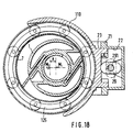
- the bearing 125 consists of a thin-walled cylindrical outer ring 126 which adapts to the configuration of the bearing bracket 110.
- standardized rolling bearings are distributed over the circumference, which are kept at a distance by means of laterally arranged elastic guide rings 127 and bolts 129.
- the radial forces Fr generated by preloading over the bearing bracket and by compression lie opposite and load the outer ring of the roller bearing 132 without any significant force on the roller elements of the bearing 132.
- the number of bearings 132 depends on the magnitude of the load.
- the bearing can be single-row (Fig. 12), double-row (Fig. 13) or comb-like at high loads (Fig. 14 and 15).
- the use of this bearing which can be manufactured inexpensively, is not limited to the use of the compressor. Oil-free operation can be ensured by using standard bearings 13 which are closed on the side.
- the limit speed of the turbo bearing is 2 - 3 times higher than the limit speed of cage-guided standard bearings in the same dimension.
- FIG. 16 shows the arrangement of a standard roller bearing on the ring piston, as can be carried out for speeds of up to approximately 4,000 revolutions per minute.
- the inner ring of the needle bearing 171 is vulcanized onto a thin-walled support ring 172 which is fastened to the annular piston 7 with a prestress by means of a tolerance spring 174.
- the tolerance springs 174 are wave-shaped or zigzag.
- the inside becomes over their pretension ring of the roller bearing 171 axially fixed.
- the rubber lining 173 is separated from the hotter surface of the annular piston 7 by the annular gap between 172 and 7. Cooling air can be supplied at the same time.
- the roller bearing 171 is not deformed, the spring action takes place via the rubber coating 173.
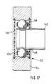
- FIG. 17 shows a special embodiment of the bearing 132 of the support turbo bearing 125.
- the bolt explained above is embodied here as a thin-walled sleeve 140, the free end 142 of which protrudes from the bearing is inserted into a corresponding bore in the elastic guide ring (not shown here) .
- the rolling elements 144 are also formed in a ring shape as rolling rollers.
- ring-shaped rolling elements designed in this way are resiliently deformable.
- the restoring forces caused by the sleeve 140 according to the invention are low and the deformability of the ring-shaped rolling elements can be used without placing too great demands on the manufacturing accuracy.
- the resilient guide ring can also press the annular rolling elements against the outer deformable support or bearing ring with radial prestress. Overall, a deformable support bearing with extremely low coefficients of friction has been created in an optimal manner. 17 are provided with sealing washers 146 and 148, so that a functionally reliable lubrication of the inner rolling elements 150 is ensured. The rolling elements 144 and the bearing or support rings of the support bearing 125 are easily ventilated and reliable heat dissipation is also ensured, especially from the area of the bearings. The temperature increase is much lower than when using conventional bearings.
Landscapes
- Engineering & Computer Science (AREA)
- General Engineering & Computer Science (AREA)
- Mechanical Engineering (AREA)
- Applications Or Details Of Rotary Compressors (AREA)
- Compressor (AREA)
- Rolling Contact Bearings (AREA)
- Rotary Pumps (AREA)
- Reciprocating Pumps (AREA)
Applications Claiming Priority (2)
| Application Number | Priority Date | Filing Date | Title |
|---|---|---|---|
| DE3542776 | 1985-12-04 | ||
| DE19853542776 DE3542776A1 (de) | 1985-12-04 | 1985-12-04 | Roll-ring-maschine zum verdichten und foerdern von fluiden |
Publications (2)
| Publication Number | Publication Date |
|---|---|
| EP0224878A2 true EP0224878A2 (fr) | 1987-06-10 |
| EP0224878A3 EP0224878A3 (fr) | 1988-09-21 |
Family
ID=6287529
Family Applications (1)
| Application Number | Title | Priority Date | Filing Date |
|---|---|---|---|
| EP86116496A Withdrawn EP0224878A3 (fr) | 1985-12-04 | 1986-11-27 | Machine pour la compression et le transport de fluides |
Country Status (4)
| Country | Link |
|---|---|
| US (1) | US4764095A (fr) |
| EP (1) | EP0224878A3 (fr) |
| JP (2) | JPS62132030A (fr) |
| DE (1) | DE3542776A1 (fr) |
Cited By (3)
| Publication number | Priority date | Publication date | Assignee | Title |
|---|---|---|---|---|
| WO1998057038A1 (fr) | 1997-06-12 | 1998-12-17 | Athanassios Nassikas | Moteur a piston rotatif a plusieurs pales |
| CN106164491A (zh) * | 2014-04-04 | 2016-11-23 | 三电国际(新加坡)私人有限公司 | 旋转叶片式压缩机及其操作方法 |
| EP3839206A1 (fr) * | 2019-12-19 | 2021-06-23 | EXDL Co., Ltd. | Moteur à palettes |
Families Citing this family (16)
| Publication number | Priority date | Publication date | Assignee | Title |
|---|---|---|---|---|
| WO1991001057A1 (fr) * | 1989-07-06 | 1991-01-24 | Australian Electro Optics Pty. Ltd. | Reseaux groupes a diodes verrouillees en phase |
| US5964584A (en) * | 1992-09-02 | 1999-10-12 | Lorentz; Bernt | Vane pump having a shaftless balanced rotor |
| US5863189A (en) * | 1995-07-10 | 1999-01-26 | Coltec Industries Inc | Variable displacement vane pump adjustable by low actuation loads |
| US6022201A (en) * | 1996-05-14 | 2000-02-08 | Kasmer Hydristor Corporation | Hydraulic vane pump with flexible band control |
| WO2004010061A2 (fr) | 2002-07-22 | 2004-01-29 | Comair Rotron, Inc. | Circuit accumulateur d'energie pour reguler la rotation d'un rotor |
| US7484944B2 (en) * | 2003-08-11 | 2009-02-03 | Kasmer Thomas E | Rotary vane pump seal |
| EP1934478B1 (fr) * | 2005-10-06 | 2009-01-28 | Joma-Hydromechanic GmbH | Pompe a palettes coulissantes |
| DE102006044948B4 (de) * | 2006-09-18 | 2010-01-07 | Iav Gmbh Ingenieurgesellschaft Auto Und Verkehr | Flügelzellenpumpe |
| ITMI20080464A1 (it) * | 2008-03-19 | 2009-09-20 | Ing Enea Mattei Spa | Espansore/compressore volumetrico a palette ad anello rotante |
| US9267504B2 (en) | 2010-08-30 | 2016-02-23 | Hicor Technologies, Inc. | Compressor with liquid injection cooling |
| CA2809945C (fr) | 2010-08-30 | 2018-10-16 | Oscomp Systems Inc. | Compresseur a refroidissement par injection de liquide |
| JP5627450B2 (ja) * | 2010-12-28 | 2014-11-19 | 三菱重工業株式会社 | 旋回輪軸受構造 |
| CN104221084B (zh) | 2012-04-30 | 2017-12-15 | 圣戈班性能塑料万科有限公司 | 带有成组的波状部的公差环 |
| CN104350299A (zh) | 2012-06-29 | 2015-02-11 | 圣戈班性能塑料万科有限公司 | 多件式公差环 |
| ITTO20121149A1 (it) * | 2012-12-27 | 2014-06-28 | Vhit Spa | Pompa a palette a cilindrata regolabile e metodo per la regolazione della cilindrata di tale pompa. |
| JP6814378B1 (ja) * | 2020-05-19 | 2021-01-20 | 泰一 岡田 | 軸受 |
Family Cites Families (14)
| Publication number | Priority date | Publication date | Assignee | Title |
|---|---|---|---|---|
| US983754A (en) * | 1910-06-16 | 1911-02-07 | Franklin Priestley Nichols | Rotary engine. |
| US1988213A (en) * | 1931-02-12 | 1935-01-15 | Racine Tool & Machine Company | Multiple rotary pump |
| US2513447A (en) * | 1946-05-17 | 1950-07-04 | Brown And Brown | Rotary pump or motor |
| US2658456A (en) * | 1948-07-29 | 1953-11-10 | Gunnar A Wahlmark | Fluid displacement device |
| FR1286068A (fr) * | 1961-01-20 | 1962-03-02 | Alsacienne D Electronique Et D | Perfectionnements aux compresseurs et pompes à vide multipalettes |
| US3272138A (en) * | 1964-02-17 | 1966-09-13 | Continental Machines | Variable volume pump with protection against overheating |
| DE1628214A1 (de) * | 1967-01-18 | 1971-11-25 | Bosch Gmbh Robert | Luftverdichter |
| FR2076180A1 (fr) * | 1970-01-05 | 1971-10-15 | Patin Pierre | Perfectionnement apporté aux roulements anti-friction et ses applications, notamment en convoyage. |
| DE7906528U1 (de) * | 1979-03-09 | 1979-12-13 | P.A. Rentrop, Hubbert & Wagner Fahrzeugausstattungen Gmbh | Maschine, insbesondere arbeitsmaschine zum verdichten und foerdern von fluiden aller art |
| DE3216010A1 (de) * | 1982-04-29 | 1983-11-10 | INA Wälzlager Schaeffler KG, 8522 Herzogenaurach | Waelzlager mit um eine achse rotierenden waelzkoerpern |
| JPS59213983A (ja) * | 1983-05-20 | 1984-12-03 | Nippon Piston Ring Co Ltd | 回転圧縮機の回転スリ−ブの流体支持装置 |
| DD225748A1 (de) * | 1983-05-31 | 1985-08-07 | Univ Magdeburg Tech | Verstelleinrichtung zur veraenderung des fluidstromes von verdraengermaschinen |
| DE3343908A1 (de) * | 1983-12-05 | 1984-06-28 | Kurt G. Ing.(grad.) 6710 Frankenthal Fickelscher | Maschine, insbesondere arbeitsmaschine zum verdichten und foerdern von fluiden aller art |
| DE3418621A1 (de) * | 1984-05-18 | 1985-11-21 | Peter South Yarra Victoria Cameron | Waelzlager |
-
1985
- 1985-12-04 DE DE19853542776 patent/DE3542776A1/de active Granted
-
1986
- 1986-11-27 EP EP86116496A patent/EP0224878A3/fr not_active Withdrawn
- 1986-12-02 JP JP61287578A patent/JPS62132030A/ja active Pending
- 1986-12-04 JP JP61289744A patent/JPS62131991A/ja active Pending
- 1986-12-04 US US06/938,208 patent/US4764095A/en not_active Expired - Fee Related
Cited By (3)
| Publication number | Priority date | Publication date | Assignee | Title |
|---|---|---|---|---|
| WO1998057038A1 (fr) | 1997-06-12 | 1998-12-17 | Athanassios Nassikas | Moteur a piston rotatif a plusieurs pales |
| CN106164491A (zh) * | 2014-04-04 | 2016-11-23 | 三电国际(新加坡)私人有限公司 | 旋转叶片式压缩机及其操作方法 |
| EP3839206A1 (fr) * | 2019-12-19 | 2021-06-23 | EXDL Co., Ltd. | Moteur à palettes |
Also Published As
| Publication number | Publication date |
|---|---|
| EP0224878A3 (fr) | 1988-09-21 |
| US4764095A (en) | 1988-08-16 |
| DE3542776A1 (de) | 1987-07-23 |
| JPS62132030A (ja) | 1987-06-15 |
| DE3542776C2 (fr) | 1987-12-03 |
| JPS62131991A (ja) | 1987-06-15 |
Similar Documents
| Publication | Publication Date | Title |
|---|---|---|
| EP0224878A2 (fr) | Machine pour la compression et le transport de fluides | |
| DE3878073T2 (de) | Fluessigkeitsverdichter. | |
| DE10240409B4 (de) | Variable Verdrängungspumpe | |
| DE3800324C2 (fr) | ||
| DE69532902T2 (de) | Rotierende Spiralverdichter | |
| EP0147654B1 (fr) | Machine en particulier pour la compression et le déplacement des fluides | |
| DE7906528U1 (de) | Maschine, insbesondere arbeitsmaschine zum verdichten und foerdern von fluiden aller art | |
| DE69020434T2 (de) | Rotationsverdichter. | |
| DE19915739A1 (de) | Mengenregelbare Flügelzellenpumpe | |
| DE3839889A1 (de) | Stroemungsmittelverdichter | |
| CH661318A5 (de) | Rotationskolbenmaschine. | |
| DE2835457C2 (fr) | ||
| DE4417161A1 (de) | Verdichter in Hypotrochoidenbauweise | |
| DE68902913T2 (de) | Fluessigkeitskompressor. | |
| DE3826548C2 (de) | Flügelzellenverdichter mit variabler Förderleistung | |
| EP1488107B1 (fr) | Pompe a excentrique et procede permettant de faire fonctionner ladite pompe | |
| DE69001910T2 (de) | Fluid-Kompressor. | |
| DE69707392T2 (de) | Pumpe mit regelbarer Durchflussmenge | |
| DE112024001038T5 (de) | Antriebswellenbaugruppen und kompressoren mit diesen | |
| DE3727281C2 (fr) | ||
| DE4326519C2 (de) | Taumelscheiben-Kompressor | |
| DE3824803C2 (fr) | ||
| DE69613643T2 (de) | Flügelzellenverdichter mit veränderlicher Durchflussmenge | |
| EP0185236B1 (fr) | Machine à piston rotatif | |
| DE10138187A1 (de) | Mengenregelbare Flügelzellenpumpe |
Legal Events
| Date | Code | Title | Description |
|---|---|---|---|
| PUAI | Public reference made under article 153(3) epc to a published international application that has entered the european phase |
Free format text: ORIGINAL CODE: 0009012 |
|
| 17P | Request for examination filed |
Effective date: 19861127 |
|
| AK | Designated contracting states |
Kind code of ref document: A2 Designated state(s): CH DE FR GB IT LI SE |
|
| PUAL | Search report despatched |
Free format text: ORIGINAL CODE: 0009013 |
|
| AK | Designated contracting states |
Kind code of ref document: A3 Designated state(s): CH DE FR GB IT LI SE |
|
| 17Q | First examination report despatched |
Effective date: 19890126 |
|
| STAA | Information on the status of an ep patent application or granted ep patent |
Free format text: STATUS: THE APPLICATION IS DEEMED TO BE WITHDRAWN |
|
| 18D | Application deemed to be withdrawn |
Effective date: 19890606 |