EP0224879B1 - Chambre de combustion pour moteur à combustion interne - Google Patents
Chambre de combustion pour moteur à combustion interne Download PDFInfo
- Publication number
- EP0224879B1 EP0224879B1 EP86116499A EP86116499A EP0224879B1 EP 0224879 B1 EP0224879 B1 EP 0224879B1 EP 86116499 A EP86116499 A EP 86116499A EP 86116499 A EP86116499 A EP 86116499A EP 0224879 B1 EP0224879 B1 EP 0224879B1
- Authority
- EP
- European Patent Office
- Prior art keywords
- combustion chamber
- fuel
- plug means
- glow plug
- swirl
- Prior art date
- Legal status (The legal status is an assumption and is not a legal conclusion. Google has not performed a legal analysis and makes no representation as to the accuracy of the status listed.)
- Expired - Lifetime
Links
- 238000002485 combustion reaction Methods 0.000 title claims description 69
- 239000000446 fuel Substances 0.000 claims description 66
- 239000007921 spray Substances 0.000 claims description 17
- 238000002347 injection Methods 0.000 claims description 14
- 239000007924 injection Substances 0.000 claims description 14
- CIWBSHSKHKDKBQ-JLAZNSOCSA-N Ascorbic acid Chemical compound OC[C@H](O)[C@H]1OC(=O)C(O)=C1O CIWBSHSKHKDKBQ-JLAZNSOCSA-N 0.000 claims description 5
- 238000010438 heat treatment Methods 0.000 claims description 5
- 230000008016 vaporization Effects 0.000 claims description 3
- 238000005507 spraying Methods 0.000 claims description 2
- OKKJLVBELUTLKV-UHFFFAOYSA-N Methanol Chemical compound OC OKKJLVBELUTLKV-UHFFFAOYSA-N 0.000 description 9
- 239000003595 mist Substances 0.000 description 6
- LFQSCWFLJHTTHZ-UHFFFAOYSA-N Ethanol Chemical compound CCO LFQSCWFLJHTTHZ-UHFFFAOYSA-N 0.000 description 3
- 230000006835 compression Effects 0.000 description 3
- 238000007906 compression Methods 0.000 description 3
- 238000010276 construction Methods 0.000 description 3
- 230000002093 peripheral effect Effects 0.000 description 3
- 238000004891 communication Methods 0.000 description 2
- 230000006866 deterioration Effects 0.000 description 2
- 239000000295 fuel oil Substances 0.000 description 2
- 239000000203 mixture Substances 0.000 description 2
- 230000015572 biosynthetic process Effects 0.000 description 1
- 239000000567 combustion gas Substances 0.000 description 1
- 230000002708 enhancing effect Effects 0.000 description 1
- 239000000463 material Substances 0.000 description 1
- 238000000034 method Methods 0.000 description 1
- 230000000149 penetrating effect Effects 0.000 description 1
- 230000000644 propagated effect Effects 0.000 description 1
- 238000011144 upstream manufacturing Methods 0.000 description 1
- 238000009834 vaporization Methods 0.000 description 1
Images

Classifications
-
- F—MECHANICAL ENGINEERING; LIGHTING; HEATING; WEAPONS; BLASTING
- F02—COMBUSTION ENGINES; HOT-GAS OR COMBUSTION-PRODUCT ENGINE PLANTS
- F02B—INTERNAL-COMBUSTION PISTON ENGINES; COMBUSTION ENGINES IN GENERAL
- F02B23/00—Other engines characterised by special shape or construction of combustion chambers to improve operation
- F02B23/08—Other engines characterised by special shape or construction of combustion chambers to improve operation with positive ignition
- F02B23/10—Other engines characterised by special shape or construction of combustion chambers to improve operation with positive ignition with separate admission of air and fuel into cylinder
- F02B23/101—Other engines characterised by special shape or construction of combustion chambers to improve operation with positive ignition with separate admission of air and fuel into cylinder the injector being placed on or close to the cylinder centre axis, e.g. with mixture formation using spray guided concepts
-
- F—MECHANICAL ENGINEERING; LIGHTING; HEATING; WEAPONS; BLASTING
- F02—COMBUSTION ENGINES; HOT-GAS OR COMBUSTION-PRODUCT ENGINE PLANTS
- F02B—INTERNAL-COMBUSTION PISTON ENGINES; COMBUSTION ENGINES IN GENERAL
- F02B19/00—Engines characterised by precombustion chambers
- F02B19/12—Engines characterised by precombustion chambers with positive ignition
-
- F—MECHANICAL ENGINEERING; LIGHTING; HEATING; WEAPONS; BLASTING
- F02—COMBUSTION ENGINES; HOT-GAS OR COMBUSTION-PRODUCT ENGINE PLANTS
- F02F—CYLINDERS, PISTONS OR CASINGS, FOR COMBUSTION ENGINES; ARRANGEMENTS OF SEALINGS IN COMBUSTION ENGINES
- F02F3/00—Pistons
- F02F3/26—Pistons having combustion chamber in piston head
-
- F—MECHANICAL ENGINEERING; LIGHTING; HEATING; WEAPONS; BLASTING
- F02—COMBUSTION ENGINES; HOT-GAS OR COMBUSTION-PRODUCT ENGINE PLANTS
- F02B—INTERNAL-COMBUSTION PISTON ENGINES; COMBUSTION ENGINES IN GENERAL
- F02B1/00—Engines characterised by fuel-air mixture compression
- F02B1/02—Engines characterised by fuel-air mixture compression with positive ignition
- F02B1/04—Engines characterised by fuel-air mixture compression with positive ignition with fuel-air mixture admission into cylinder
-
- F—MECHANICAL ENGINEERING; LIGHTING; HEATING; WEAPONS; BLASTING
- F02—COMBUSTION ENGINES; HOT-GAS OR COMBUSTION-PRODUCT ENGINE PLANTS
- F02B—INTERNAL-COMBUSTION PISTON ENGINES; COMBUSTION ENGINES IN GENERAL
- F02B23/00—Other engines characterised by special shape or construction of combustion chambers to improve operation
- F02B23/08—Other engines characterised by special shape or construction of combustion chambers to improve operation with positive ignition
- F02B23/10—Other engines characterised by special shape or construction of combustion chambers to improve operation with positive ignition with separate admission of air and fuel into cylinder
- F02B2023/103—Other engines characterised by special shape or construction of combustion chambers to improve operation with positive ignition with separate admission of air and fuel into cylinder the injector having a multi-hole nozzle for generating multiple sprays
-
- F—MECHANICAL ENGINEERING; LIGHTING; HEATING; WEAPONS; BLASTING
- F02—COMBUSTION ENGINES; HOT-GAS OR COMBUSTION-PRODUCT ENGINE PLANTS
- F02B—INTERNAL-COMBUSTION PISTON ENGINES; COMBUSTION ENGINES IN GENERAL
- F02B23/00—Other engines characterised by special shape or construction of combustion chambers to improve operation
- F02B23/08—Other engines characterised by special shape or construction of combustion chambers to improve operation with positive ignition
- F02B23/10—Other engines characterised by special shape or construction of combustion chambers to improve operation with positive ignition with separate admission of air and fuel into cylinder
- F02B2023/108—Swirl flow, i.e. the axis of rotation of the main charge flow motion is vertical
-
- F—MECHANICAL ENGINEERING; LIGHTING; HEATING; WEAPONS; BLASTING
- F02—COMBUSTION ENGINES; HOT-GAS OR COMBUSTION-PRODUCT ENGINE PLANTS
- F02B—INTERNAL-COMBUSTION PISTON ENGINES; COMBUSTION ENGINES IN GENERAL
- F02B75/00—Other engines
- F02B75/12—Other methods of operation
- F02B2075/125—Direct injection in the combustion chamber for spark ignition engines, i.e. not in pre-combustion chamber
-
- Y—GENERAL TAGGING OF NEW TECHNOLOGICAL DEVELOPMENTS; GENERAL TAGGING OF CROSS-SECTIONAL TECHNOLOGIES SPANNING OVER SEVERAL SECTIONS OF THE IPC; TECHNICAL SUBJECTS COVERED BY FORMER USPC CROSS-REFERENCE ART COLLECTIONS [XRACs] AND DIGESTS
- Y02—TECHNOLOGIES OR APPLICATIONS FOR MITIGATION OR ADAPTATION AGAINST CLIMATE CHANGE
- Y02T—CLIMATE CHANGE MITIGATION TECHNOLOGIES RELATED TO TRANSPORTATION
- Y02T10/00—Road transport of goods or passengers
- Y02T10/10—Internal combustion engine [ICE] based vehicles
- Y02T10/12—Improving ICE efficiencies
Definitions
- the present invention relates to a combustion chamber for an internal combustion engine, comprising: a combustion chamber in which a swirl is formed; a fuel injection nozzle means for spraying fuel in atomized condition towards an inner wall of said combustion chamber; a glow plug means for heating air inside the combustion chamber and for vaporizing the fuel sprayed in atomized condition; a spark plug means for igniting the vaporized fuel, said spark plug means being disposed downstream of the glow plug means in the direction of the swirl.
- the invention is concerned with a combustion chamber of an internal combustion engine which permits the use of volatile fuels of low cetane number such as gasoline and alcohol.
- a precombustion chamber (b) is provided sideways at the top of a cylinder (a), a preheating plug (d) is disposed obliquely in a bottom wall portion (c) of the precombustion chamber (b), further a fuel injection valve (e) is disposed opposedly to the preheating plug (d), and a spark plug (f) is disposed between the fuel injection valve (e) and the preheating plug (d).
- a glow plug is used to raise the temperature in the precombustion chamber to ignite and burn fuel in order to improve the engine start-up characteristic and drivability in a low load condition.
- the precombustion chamber (b) of the cylinder (a) is in communication with a main combustion chamber (g) of a piston (i) through a throat (h), a throttle loss at the time of introducing of compressed air into the preheating chamber (b) and a heat loss at the time of flowing of combustion gas from the precombustion chamber (b) into the main combustion chamber (g) are large, thus causing deterioration of the thermal efficiency.
- a combustion chamber for an internal combustion engine of the type mentioned in the beginning is known from FR-A-1 015 003.
- the fuel is sprayed into the air stream between the glow plug and the spark plug in a direction towards the opposite chamber wall, such that the fuel passes into a stream of preheated air prior to reaching the spark plug.
- it is desirable to enhance the combustion if fuel of low cetane number is used, particularly at start-up at a low outside air temperature of -20°C or lower.
- WO-A-85/00197 shows a centrally located nozzle and a glow plug within a combustion chamber in the top of a piston.
- This document teaches the propagation of a flame from an ignition point to other fuel sprays, and the central location of the nozzle means supplying a plurality of fuel sprays.
- the glow plug is outside the fuel sprays in a pocket of intake air which separates the fuel sprays.
- the present invention has been accomplished for overcoming the above-mentioned various problems and it is the object thereof to provide a combustion chamber of an internal combustion engine capable of burning well volatile fuels of low cetane number such as alcohol and gasoline in all load conditions including low temperature start-up.
- a combustion chamber for an internal combustion engine of the type mentioned in the beginning which is characterized in that said nozzle means supplies a plurality of fuel sprays and said glow plug means is disposed on an injection line of one of said fuel sprays such that the fuel spray is further atomized upon collision with the glow plug means.
- a further development of this combustion chamber according to the invention is characterized in that said one fuel spray is ignited by the spark plug means and other fuel sprays are ignited by flame built by said one fuel spray.
- the glow plug means and the spark plug means are disposed in positions close to each other along a flowing direction of the swirl, and also disposed is the fuel injection nozzle means for injecting a spray of fuel on the glow plug means.
- the operation of the above construction will now be described.
- the atomized fuel is vaporized acceleratively by an air current of high temperature created by the heat generating portion of the glow plug means.
- the vaporized fuel mist is allowed to flow to a discharge portion of the spark plug means while mixing with air, and when discharge is made at the discharge portion upon arrival of the vaporized fuel mist-air mixture at the discharge portion, ignition is made in an instant and combustion is effected in a satisfactory manner.
- the reference numeral 1 denotes a piston top
- numeral 2 denotes a combustion chamber formed by deeply recessing the piston top 1 axially downwardly with respect to a top surface 1a
- numeral 5 denotes a cylinder head.
- a rotating current of intake air from a swirl port (not shown).
- the combustion chamber 2 is formed generally circularly in its transverse section perpendicular to the axis of the piston 1, so that the said rotating current becomes a swirl S flowing along an inner peripheral wall 2a of the combustion chamber 2.
- the combustion chamber of the internal combustion engine of the present invention is characteristic in that volatile fuels of low cetane number can be burnt well without misfire even at the time of start-up of the engine at a low temperature.
- a fuel injecting nozzle means for supplying atomized fuel into the combustion chamber 2 a spark plug means as an ignition accelerating means, and a glow plug means, are constructed and disposed as follows.
- a spark plug means 3 is integrally fixed into the cylinder head 5 so that a discharge portion 3a thereof is positioned near the inner peripheral wall 2a of the combustion chamber 2 when the piston 1 is about to terminate its compression stroke.
- a glow plug means 4 is fixed integrally into the cylinder head 5 in a position in which a heat generating portion 4a thereof is located near the inner peripheral wall 2a of the combustion chamber 2 when the piston 1 is about to terminate its compression stroke.
- the glow plug means 4 is disposed so that the heat generating portion 4a thereof is positioned on an upstream side of the swirl S and in the vicinity of the discharge portion 3a of the spark plug means 3.
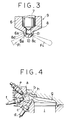
- a fuel injecting nozzle means 9 there is adopted such a structure as shown in Fig. 3.
- a needle valve 7 is disposed vertically movably within a cylindrical nozzle body 6.
- a valve seat 8 for a seat portion 6a of the needle valve 7.
- a fuel injection chamber 10 which is brought into communication with a fuel chamber (not shown) in the nozzle body 6 when the seat portion 6a is spaced apart from the valve seat 8.
- nozzle holes 8a, 8b, 8c and 8d in a circumferentially spaced relation.
- a diameter d1 of each of the nozzle holes 8a - 8d is set so that the atomized fuel mist injected from the nozzle holes has an appropriate penetrating force for the swirl S in the combustion chamber 2 and has an appropriate spread for the combustion chamber 2.
- the fuel injecting nozzle means 9 thus constructed is integrally fixed into the cylinder head 5 so that it is positioned approximately centrally relative to the cumbustion chamber 2 and the nozzle holes 8b - 8d face the inner wall 2a of the combustion chamber 2 when the piston 1 is about to terminate its compression stroke.
- the number of the nozzle holes is four, and one of the nozzle holes 8a - 8d, for example the nozzle hole 8a, is determined its opening direction so that fuel mist F1 can be fed toward the glow plug means 4 or thereabouts.
- the glow plug means 4 is energized to heat the heat generating portion 4a to redness, so a high-temperature air current V is created locally downstream of the swirl near the heat generating portion 4a of the glow plug means 4.
- the fuel mist F1 impinging on the heat generating portion 4a of the glow plug means 4 after atomized injection from the nozzle hole 8a is finely pulverized by the injection and at the same time it is vaporized in an instant by a high-temperature heat of the heat generating portion 4a, which vapor is allowed to flow to the downstream side of the swirl S.
- fuel vapor layers E2 - E4 are formed, and consequently the flame group G is propagated successively to the circumferentially adjacent fuel vapor layers E2 - E4, whereby a complete combustion in the combustion chamber 2 is attained.
- the glow plug means 4 can be heated even when the engine load is low and the mixture is lean, and by the heating thereof there can be formed the strong flame group G mentioned above. As a result, a stabler combustion is ensured in every load condition.
Landscapes
- Engineering & Computer Science (AREA)
- Chemical & Material Sciences (AREA)
- Combustion & Propulsion (AREA)
- Mechanical Engineering (AREA)
- General Engineering & Computer Science (AREA)
- Combustion Methods Of Internal-Combustion Engines (AREA)
- Ignition Installations For Internal Combustion Engines (AREA)
Claims (7)
- Chambre de combustion pour un moteur à combustion interne comprenant :
une chambre de combustion (2) dans laquelle se forme un tourbillon (S) ;
des moyens formant injecteur de carburant (9) servant à projeter un carburant (F₁ à F₄) dans l'état atomisé vers une paroi interne (2a) de ladite chambre de combustion (2) ;
des moyens formant bougie incandescente (4) servant à chauffer l'air à l'intérieur de la chambre de combustion (2) et à vaporiser le carburant (F₁ à F₄) projeté dans un état atomisé ;
des moyens formant bougie d'allumage (3) servant à allumer le carburant vaporisé (F₁ à F₄), lesdits moyens du type bougie d'allumage (3) étant disposés en aval des moyens formant bougie incandescente (4) dans le sens de l'écoulement du tourbillon (S),
caractérisée en ce que
lesdits moyens formant injecteur (9) débitent une pluralité de jets de carburant pulvérisé (F₁ à F₄) et lesdits moyens formant bougie incandescente (4) sont disposés sur la droite d'injection d'un premier (F₁) desdits jets de carburant pulvérisé (F₁ à F₄) de sorte que ledit jet de carburant pulvérisé (F₁) est encore plus finement atomisé en entrant en collision avec les moyens formant bougie incandescente (4). - Chambre de combustion pour un moteur à combustion interne selon la revendication 1, caractérisée en ce que ledit premier jet de carburant pulvérisé (F₁) est allumé par la bougie d'allumage (3) et que les autres jets de carburant pulvérisé (F₂ à F₄) sont allumés par la flamme formée par ledit premier jet de carburant pulvérisé (F₁).
- Chambre de combustion selon la revendication 1, caractérisée en ce que
la chambre de combustion (2) est définie par un évidement formé dans la partie haute (1) d'un piston ;
les moyens formant bougie incandescente (4) sont supportés par une culasse de cylindre (5), avec leur partie chauffante (4a) exposée dans la chambre de combustion (2) et ;
les moyens formant bougie d'allumage (3) sont supportés par la culasse (5) du cylindre, avec leur électrode (3a) exposée dans la chambre de combustion (2). - Chambre de combustion de moteur à combustion interne selon la revendication 3, caractérisée en ce que lesdits moyens formant injecteur de carburant (9) possèdent une pluralité de trous (8a à 8d) d'atomisation et de distribution du carburant, situés à intervalles dans la direction circonférentielle, lesdits moyens formant injecteur de carburant (9) étant positionnés à peu près au centre de ladite chambre de combustion (2) dans laquelle se forme ledit tourbillon (S).
- Chambre de combustion de moteur à combustion interne selon la revendication 3, caractérisée en ce que ladite chambre de combustion (2), dans laquelle se forme un tourbillon (S), est circulaire dans une section transversale perpendiculaire à son axe.
- Chambre de combustion de moteur à combustion interne selon la revendication 4, caractérisée en ce que la section transversale de la chambre de combustion (2) perpendiculairement à son axe présente la forme d'un polygone tel qu'un triangle, un carré ou un pentagone.
- Chambre de combustion selon une quelconque des revendications 1 à 6, dans laquelle ledit carburant est un carburant volatil à bas indice de cétane.
Applications Claiming Priority (2)
| Application Number | Priority Date | Filing Date | Title |
|---|---|---|---|
| JP60270288A JPS62129514A (ja) | 1985-11-30 | 1985-11-30 | 内燃機関の燃焼室 |
| JP270288/85 | 1985-11-30 |
Publications (3)
| Publication Number | Publication Date |
|---|---|
| EP0224879A2 EP0224879A2 (fr) | 1987-06-10 |
| EP0224879A3 EP0224879A3 (en) | 1988-08-24 |
| EP0224879B1 true EP0224879B1 (fr) | 1992-03-04 |
Family
ID=17484171
Family Applications (1)
| Application Number | Title | Priority Date | Filing Date |
|---|---|---|---|
| EP86116499A Expired - Lifetime EP0224879B1 (fr) | 1985-11-30 | 1986-11-27 | Chambre de combustion pour moteur à combustion interne |
Country Status (4)
| Country | Link |
|---|---|
| US (1) | US4712525A (fr) |
| EP (1) | EP0224879B1 (fr) |
| JP (1) | JPS62129514A (fr) |
| DE (1) | DE3684106D1 (fr) |
Families Citing this family (15)
| Publication number | Priority date | Publication date | Assignee | Title |
|---|---|---|---|---|
| DE3734737A1 (de) * | 1986-10-14 | 1988-04-21 | Orbital Eng Pty | Brennstoffeinspritzsystem und mit diesem ausgeruestete verbrennungsmaschine |
| US5058548A (en) * | 1989-06-26 | 1991-10-22 | Fuji Jukogyo Kabushiki Kaisha | Combustion chamber of an internal combustion engine |
| US5042442A (en) * | 1990-04-10 | 1991-08-27 | Hale Fire Pump Company | Internal combustion engine |
| ATE148199T1 (de) * | 1992-11-26 | 1997-02-15 | Avl Verbrennungskraft Messtech | Fremdgezündete brennkraftmaschine mit einem im kolben zugeordneten brennraum |
| US7703438B2 (en) * | 2006-06-16 | 2010-04-27 | Ford Global Technologies, Llc | System and method for facilitating homogeneous charge compression ignition |
| US7690368B2 (en) * | 2006-06-16 | 2010-04-06 | Ford Global Technologies, Llc | System and method for facilitating homogeneous charge compression ignition |
| DE102006052634A1 (de) * | 2006-11-08 | 2008-05-15 | Robert Bosch Gmbh | Kraftstoffheizer |
| JP5316056B2 (ja) * | 2009-02-16 | 2013-10-16 | トヨタ自動車株式会社 | プラズマ点火装置を備える内燃機関 |
| DE102009016461A1 (de) * | 2009-04-04 | 2010-10-07 | Man Diesel Se | Zündanordnung für einen Gasmotor, mit dieser ausgerüsteter Gasmotor und Verfahren zum Betreiben des Gasmotors |
| DE102009047021A1 (de) * | 2009-11-23 | 2011-05-26 | Robert Bosch Gmbh | Laserzündkerze |
| US9353674B2 (en) * | 2010-11-01 | 2016-05-31 | Mahle Powertrain, Llc | Turbulent jet ignition pre-chamber combustion system for spark ignition engines |
| JP6076662B2 (ja) * | 2012-09-20 | 2017-02-08 | 三菱重工業株式会社 | 副室式ガスエンジン |
| JP6217670B2 (ja) * | 2015-03-04 | 2017-10-25 | トヨタ自動車株式会社 | 内燃機関 |
| DE102017009228A1 (de) * | 2017-10-04 | 2019-04-04 | Daimler Ag | Verbrennungskraftmaschine für ein Kraftfahrzeug |
| US10557403B2 (en) * | 2018-01-31 | 2020-02-11 | Fca Us Llc | Venturi-based purge vapor supply system for turbulent jet ignition engines |
Family Cites Families (16)
| Publication number | Priority date | Publication date | Assignee | Title |
|---|---|---|---|---|
| FR1015003A (fr) * | 1950-03-24 | 1952-08-26 | Dispositif permettant la transformation d'un moteur à essence en un moteur à injection utilisant les combustibles lourds | |
| GB704800A (en) * | 1951-10-16 | 1954-03-03 | Texaco Development Corp | Improvements in or relating to an internal combustion engine |
| FR1076741A (fr) * | 1952-06-20 | 1954-10-28 | Moteur à injection directe de combustible | |
| FR1198580A (fr) * | 1957-10-09 | 1959-12-08 | Schlepperwerk Nordhausen Veb | Moteur à compression d'air et à auto-allumage |
| GB1363107A (en) * | 1971-09-21 | 1974-08-14 | Kloeckner Humboldt Deutz Ag | Reciprocating-piston fuel injection internal combustion engine |
| DE2154341A1 (de) * | 1971-11-02 | 1973-05-10 | Daimler Benz Ag | Vielstoff-hubkolben-brennkraftmaschine |
| US3945351A (en) * | 1974-07-19 | 1976-03-23 | Isuzu Motors Limited | Combustion chamber of a direct fuel injection type diesel engine |
| AU508702B2 (en) * | 1975-10-23 | 1980-03-27 | Tokai Trw & Co., Ltd | Ignition method for internal combustion engine |
| JPS5381836A (en) * | 1976-12-26 | 1978-07-19 | Nippon Soken Inc | Rotary engine ignition system |
| JPS53115424A (en) * | 1977-03-17 | 1978-10-07 | Nippon Soken Inc | Ignition device for rotary piston engine |
| JPS60500341A (ja) * | 1983-01-10 | 1985-03-14 | フオ−ド モ−タ− カンパニ− | 高蒸発熱燃料で機関を運転する方法 |
| US4548172A (en) * | 1983-06-22 | 1985-10-22 | Caterpillar Tractor Co. | Ignition-assisted fuel combustion system |
| GB2169656B (en) * | 1985-01-15 | 1988-01-20 | Yanmar Diesel Engine Co | Diesel engine piston combustion chamber |
| ATA129885A (de) * | 1985-05-02 | 1987-02-15 | Steyr Daimler Puch Ag | Luftverdichtende hubkolben-brennkraftmaschine |
| AT384078B (de) * | 1985-05-14 | 1987-09-25 | Steyr Daimler Puch Ag | Luftverdichtende hubkolben-brennkraftmaschine |
| US4709672A (en) * | 1985-05-21 | 1987-12-01 | Isuzu Motors Limited | Combustion chamber for an internal-combustion engine |
-
1985
- 1985-11-30 JP JP60270288A patent/JPS62129514A/ja active Pending
-
1986
- 1986-11-26 US US06/935,357 patent/US4712525A/en not_active Expired - Fee Related
- 1986-11-27 DE DE8686116499T patent/DE3684106D1/de not_active Expired - Fee Related
- 1986-11-27 EP EP86116499A patent/EP0224879B1/fr not_active Expired - Lifetime
Also Published As
| Publication number | Publication date |
|---|---|
| DE3684106D1 (de) | 1992-04-09 |
| EP0224879A3 (en) | 1988-08-24 |
| JPS62129514A (ja) | 1987-06-11 |
| US4712525A (en) | 1987-12-15 |
| EP0224879A2 (fr) | 1987-06-10 |
Similar Documents
| Publication | Publication Date | Title |
|---|---|---|
| EP0621402B1 (fr) | Disposition et procédé d'injection et allumage pour un moteur à combustion interne | |
| JP2590170B2 (ja) | 燃料燃焼システム用の火炎培養増殖装置 | |
| US6845746B2 (en) | Internal combustion engine with injection of gaseous fuel | |
| EP0249699B1 (fr) | Moteur à combustion interne à injection de carburant | |
| US4546740A (en) | Ignition source for internal combustion engine | |
| US4712525A (en) | Combustion chamber of internal combustion engine | |
| US5170758A (en) | Valve-controlled internal combustion engine with air compression | |
| CN101094978A (zh) | 把气态燃料喷射到内燃机中的方法 | |
| US4125094A (en) | Internal combustion engine with an auxiliary combustion chamber | |
| WO1985000197A1 (fr) | Systeme de combustion de carburant aide par allumage | |
| US4557231A (en) | Combustion chamber of a reciprocating internal combustion engine which promotes a rotary combustion turbulence | |
| EP0205000B1 (fr) | Chambre de combustion pour moteur à combustion interne | |
| EP0225637B1 (fr) | Chambre de combustion pour moteur à combustion interne | |
| JPH02153221A (ja) | 火花点火ガスエンジン | |
| JP2629745B2 (ja) | スパークアシストディーゼル機関 | |
| JPH0755295Y2 (ja) | 内燃機関の燃焼室 | |
| JPS61167116A (ja) | 補助点火式デイ−ゼルエンジン | |
| JPH0748982Y2 (ja) | 内燃機関の燃焼装置 | |
| US4114569A (en) | Internal combustion engine with an auxiliary combustion chamber | |
| JP2521902B2 (ja) | 内燃機関の燃焼室 | |
| JP2521914B2 (ja) | 内燃機関 | |
| JPH059617B2 (fr) | ||
| CN115387898A (zh) | 一种内燃机及其点火控制方法 | |
| JPH063133B2 (ja) | 直噴式デイーゼルエンジンの燃焼室 | |
| JPH0584814B2 (fr) |
Legal Events
| Date | Code | Title | Description |
|---|---|---|---|
| PUAI | Public reference made under article 153(3) epc to a published international application that has entered the european phase |
Free format text: ORIGINAL CODE: 0009012 |
|
| AK | Designated contracting states |
Kind code of ref document: A2 Designated state(s): DE FR GB |
|
| PUAL | Search report despatched |
Free format text: ORIGINAL CODE: 0009013 |
|
| AK | Designated contracting states |
Kind code of ref document: A3 Designated state(s): DE FR GB |
|
| 17P | Request for examination filed |
Effective date: 19890119 |
|
| 17Q | First examination report despatched |
Effective date: 19890608 |
|
| GRAA | (expected) grant |
Free format text: ORIGINAL CODE: 0009210 |
|
| AK | Designated contracting states |
Kind code of ref document: B1 Designated state(s): DE FR GB |
|
| REF | Corresponds to: |
Ref document number: 3684106 Country of ref document: DE Date of ref document: 19920409 |
|
| ET | Fr: translation filed | ||
| PLBE | No opposition filed within time limit |
Free format text: ORIGINAL CODE: 0009261 |
|
| STAA | Information on the status of an ep patent application or granted ep patent |
Free format text: STATUS: NO OPPOSITION FILED WITHIN TIME LIMIT |
|
| 26N | No opposition filed | ||
| PGFP | Annual fee paid to national office [announced via postgrant information from national office to epo] |
Ref country code: FR Payment date: 20001009 Year of fee payment: 15 |
|
| PGFP | Annual fee paid to national office [announced via postgrant information from national office to epo] |
Ref country code: GB Payment date: 20001017 Year of fee payment: 15 |
|
| PGFP | Annual fee paid to national office [announced via postgrant information from national office to epo] |
Ref country code: DE Payment date: 20001020 Year of fee payment: 15 |
|
| PG25 | Lapsed in a contracting state [announced via postgrant information from national office to epo] |
Ref country code: GB Free format text: LAPSE BECAUSE OF NON-PAYMENT OF DUE FEES Effective date: 20011127 |
|
| REG | Reference to a national code |
Ref country code: GB Ref legal event code: IF02 |
|
| PG25 | Lapsed in a contracting state [announced via postgrant information from national office to epo] |
Ref country code: DE Free format text: LAPSE BECAUSE OF NON-PAYMENT OF DUE FEES Effective date: 20020702 |
|
| GBPC | Gb: european patent ceased through non-payment of renewal fee |
Effective date: 20011127 |
|
| PG25 | Lapsed in a contracting state [announced via postgrant information from national office to epo] |
Ref country code: FR Free format text: LAPSE BECAUSE OF NON-PAYMENT OF DUE FEES Effective date: 20020730 |
|
| REG | Reference to a national code |
Ref country code: FR Ref legal event code: ST |
|
| REG | Reference to a national code |
Ref country code: FR Ref legal event code: ST |