EP0224983B1 - Dispositif pour le relevage et l'abaissement d'une perche de trolley - Google Patents
Dispositif pour le relevage et l'abaissement d'une perche de trolley Download PDFInfo
- Publication number
- EP0224983B1 EP0224983B1 EP86305597A EP86305597A EP0224983B1 EP 0224983 B1 EP0224983 B1 EP 0224983B1 EP 86305597 A EP86305597 A EP 86305597A EP 86305597 A EP86305597 A EP 86305597A EP 0224983 B1 EP0224983 B1 EP 0224983B1
- Authority
- EP
- European Patent Office
- Prior art keywords
- pole
- support structure
- motor
- arm
- collar
- Prior art date
- Legal status (The legal status is an assumption and is not a legal conclusion. Google has not performed a legal analysis and makes no representation as to the accuracy of the status listed.)
- Expired - Lifetime
Links
- 230000007246 mechanism Effects 0.000 claims description 10
- 230000002441 reversible effect Effects 0.000 claims description 6
- 230000000694 effects Effects 0.000 abstract description 2
- 238000004804 winding Methods 0.000 description 9
- 210000005069 ears Anatomy 0.000 description 7
- 230000009471 action Effects 0.000 description 3
- 238000010586 diagram Methods 0.000 description 2
- 230000003028 elevating effect Effects 0.000 description 2
- 230000005484 gravity Effects 0.000 description 2
- 239000012212 insulator Substances 0.000 description 2
- 230000000712 assembly Effects 0.000 description 1
- 238000000429 assembly Methods 0.000 description 1
- 230000008901 benefit Effects 0.000 description 1
- 238000010292 electrical insulation Methods 0.000 description 1
- 239000011152 fibreglass Substances 0.000 description 1
- 238000000034 method Methods 0.000 description 1
- 230000004048 modification Effects 0.000 description 1
- 238000012986 modification Methods 0.000 description 1
- 239000012811 non-conductive material Substances 0.000 description 1
- 230000008569 process Effects 0.000 description 1
- 230000004044 response Effects 0.000 description 1
- 238000003466 welding Methods 0.000 description 1
Images


Classifications
-
- B—PERFORMING OPERATIONS; TRANSPORTING
- B60—VEHICLES IN GENERAL
- B60L—PROPULSION OF ELECTRICALLY-PROPELLED VEHICLES; SUPPLYING ELECTRIC POWER FOR AUXILIARY EQUIPMENT OF ELECTRICALLY-PROPELLED VEHICLES; ELECTRODYNAMIC BRAKE SYSTEMS FOR VEHICLES IN GENERAL; MAGNETIC SUSPENSION OR LEVITATION FOR VEHICLES; MONITORING OPERATING VARIABLES OF ELECTRICALLY-PROPELLED VEHICLES; ELECTRIC SAFETY DEVICES FOR ELECTRICALLY-PROPELLED VEHICLES
- B60L5/00—Current collectors for power supply lines of electrically-propelled vehicles
- B60L5/04—Current collectors for power supply lines of electrically-propelled vehicles using rollers or sliding shoes in contact with trolley wire
- B60L5/12—Structural features of poles or their bases
- B60L5/16—Devices for lifting and resetting the collector
-
- Y—GENERAL TAGGING OF NEW TECHNOLOGICAL DEVELOPMENTS; GENERAL TAGGING OF CROSS-SECTIONAL TECHNOLOGIES SPANNING OVER SEVERAL SECTIONS OF THE IPC; TECHNICAL SUBJECTS COVERED BY FORMER USPC CROSS-REFERENCE ART COLLECTIONS [XRACs] AND DIGESTS
- Y02—TECHNOLOGIES OR APPLICATIONS FOR MITIGATION OR ADAPTATION AGAINST CLIMATE CHANGE
- Y02T—CLIMATE CHANGE MITIGATION TECHNOLOGIES RELATED TO TRANSPORTATION
- Y02T10/00—Road transport of goods or passengers
- Y02T10/60—Other road transportation technologies with climate change mitigation effect
- Y02T10/72—Electric energy management in electromobility
Definitions
- This invention relates to an improved apparatus for controlling the movement of a trolley pole into and out of contact with an overhead wire and for the positioning of the pole when it is partly or fully lowered.
- US-A-2,224,149 discloses a device for raising and lowering a trolley pole, and whereby the pole can be reengaged with the line if it jumps off the line; the device including a pivotally mounted support structure and springs for biassing the pole.
- the device of EP-A-0155584 is for keeping the trolley pole parallel to the long axis of the vehicle during raising and lowering the pole, and it includes pheumatic cylinder assemblies connected to the pole and to a pivot point.
- Another object is to provide such an apparatus which accomplishes the function of lowering and stowing the pole without further extension of the trolley base springs, thereby prolonging the life of those springs.
- Apparatus for raising and lowering the current collecting pole of an electrically driven vehicle comprises according to the invention a base plate mountable on a vehicle, a trolley pole support structure pivotally mounted on the base plate about a first substantially horizontal axis, a trolley pole pivotally mounted on the support structure for pivotal movement about a second substantially horizontal axis, and spring-means coupled between the support structure and the pole for urging the pole toward a raised position, characterized by an actuator means mounted on the base plate and having an extensible arm connected to the support structure, the actuator including a reversible electric motor and gears connected to the motor for driving the extensible arm, and control means for selectively energizing the motor and the gears to extend and retract the extensible arm and to pivot the support structure about the first horizontal axis, thereby raising or lowering the trolley pole between an upright position and a tilted, stowed position.
- said support structure includes a pole support collar mounted for rotation about an axis which is substantially vertical when said support structure is in said upright position, said trolley pole being pivotably mounted on said collar; means on said collar defining a recess facing radially away from said substantial vertical axis; and a latch member pivotably mounted on said support structure and extending below said recess in said upright position so that, when said support structure is tilted away from said upright position said latch member enters said recess and substantially prevents rotation of said collar.
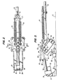
- a trolley pole 10 is mounted on a vehicle 12 by a raising and lowering support mechanism indicated generally at 14.
- Pole 10 is conventional in that it is an elongated, substantially rigid member having a degree of flexibility so as to suitably support a current collector at the distal end thereof in a position to contact an overhead wire, in a manner well known in this art, so as to act as a current collector.
- the harp and the associated current-carrying wires are omitted from the figures herein because they are fully conventional and because their omission simplifies the illustrations.
- a cable 15 is connected to an intermediate point on the pole and leads to a retracting mechanism 17 which accepts cable as the pole is lowered, the cable and retractor acting to maintain proper conditions concerning the relationship of the harp to the overhead wire under normal operating circumstances.
- the cable and retractor are fully conventional.
- the apparatus also includes base springs 18 and 19 which are connected between a location on the pole and a location on the base structure, which will be further described, for the purpose of urging the pole toward its elevated position to keep the current-collecting harp in contact with the overhead wire under normal operating conditions.
- the springs are connected to opposite ends of a double hook 21 which is attached to an adjusting mechanism 22, this attachment also being conventional in nature.
- the support mechanism in accordance with the invention includes a base plate 25 which is fixedly attached, as by a plurality of machine screws or bolts, to the upper surface of vehicle 12.
- Plate 25 is in the shape of an elongated rectangle the longitudinal central axis of which is aligned with the fore-and-aft axis of vehicle 12, i.e. with the direction of motion of the vehicle which is indicated by arrow 26.
- bracket 28 At the forward end of plate 25 is a bracket 28 having an end plate and triangular side brace plates 29, the plates 29 being rigidly attached to base plate 25 as by welding.
- Bracket 28 also includes a vertically extending central post 31 with ears 32 at its upper end which have a transverse hole extending therethrough.
- An actuator indicated generally at 33 includes a gearbox 34, a motor 35 and an elongated actuator arm housing 36 which contains an extendible arm 37, best seen in Fig. 3.
- Gearbox 34 has a post 39 extending from the forward surface thereof between ears 32, the post having an opening therethrough aligned with the openings in ears 32 to receive a pivot pin 38 so that gearbox 34 is pivotally connected to post 31 and can swing upwardly, as required, and downwardly to a limited extent, the downward motion being limited by limits on the movement of the base structure.
- Actuator 33 is, in itself, a conventional kind of electrically driven linear actuator which is particularly advantageous for the present apparatus because it is light in weight, has high output force and high efficiency and also is operated using a 12 volt DC reversible motor.
- An actuator of a suitable type is manufactured by the Warner Electric Brake and Clutch Company of South Beloit, Illinois U.S.A. Such actuators make use of the ball screw type of mechanism as shown in U.S. Patents 4,266,437 and 4,286,793. Other forms of actuators can be used.
- a transversely extending axle 43 which rotatably supports a vertically oriented pivot plate 40.
- An upwardly extending stop member 41 is fixedly attached to plate 25 and has a central groove with a stop surface, see Fig. 5, which contacts the lower forward edge of pivot plate 40, establishing the forward, operating position of the support structure. Stop 41 also provides lateral support for plate 40 in the operating position and establishes the limit on downward movement of gearbox 34.
- An upwardly extending link 42 which is pivotally attached to the rear end of extendible arm 37.
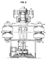
- a horizontal support plate 44 is fixedly attached to pivot plate 40 and supports four sets of insulators 46 which, in turn, support a second generally horizontal support plate 48. Plates 44 and 48 are held in parallel relationship with each other by the interconnected insulators.
- Plate 48 has a generally circular conical portion 50 in which is fixedly mounted a vertically extending shaft 52 which receives a rotatable collar 54.
- Collar 54 is provided with a yoke 56 to which the forward ends of springs 18, 19 are attached and also has a rearwardly protruding bracket 58 to which the end of pole 10 is pivotally connected.
- a normally closed limit switch 69 is attached to base plate 25 in a position such that plate 44 comes in contact with the actuating arm of the limit switch when the pole reaches its elevated position.
- a circuit for motor 35 is energized through switch 69 so that when the support structure reaches the desired position the switch is opened and the motor is deenergized.
- a second limit switch 70 is positioned so that its actuator arm is contacted by plate 44 when the support structure reaches the tilted position. Again, when switch 70 is opened, the motor is deenergized and motion is stopped.
- the apparatus thus far described forms the basic mechanism for lowering pole 10 in the desired manner.
- actuator 33 When motor 35 is energized, actuator 33 is caused to extend its extendible arm 37, pushing on link 42 and pivoting plate 40 about the axis of axle 43, thereby tilting the support structure including plates 44 and 48, shaft 52 and collar 54,toward the rear of the vehicle, tilting the vertical axis about which collar 54 is rotatable and lowering the pole.
- Several events occur during this lowering which are of interest.
- One is that, by tilting the collar and shaft 52, the pole is caused to automatically move to the center position under the force of gravity.
- a second important benefit is that the lowering is accomplished without any further extension of springs 18 and 19 which is common practice.
- the lowering allows the springs to contract, thereby significantly lengthening the spring life by lowering stress in the springs.
- the actuator 33 is of a type which resists forces applied to its extendible arm, the structure is essentially locked in the tilted position simply by deenergizing motor 35. Cable 15 is, of course, retracted by retractor 17.
- pole 10 is centered automatically by the tilting action, it is apparent that the pole would not remain in the center position if subjected to lateral forces by the movement of vehicle 12.
- a simple but highly effective centering device is therefore provided, this device also performing the important function of guiding the pole in its travel upwardly from the stowed position to the point of harp contact with the trolley wire.
- the centering structure is shown in Fig. 4 and includes a pair of forwardly protruding ears 60 and 61 which are fixedly attached to collar 54 and extend parallel with each other from that collar, thereby defining a recess.
- a centering latch arm 62 is pivotally connected to a bracket 64 at the forward end of plate 48, arm 62 having a latch member 63 protruding rearwardly from the pivot point and a balance arm 65 extending forwardly therefrom.
- Balance arm 65 has a head 67 at the distal end thereof, the lower end of the head having a roller 68 which rests on and rides along the upper surface of actuator arm housing 36.
- Arm 65 is a rod of electrically nonconductive material such as fiberglass which provides electrical insulation and also serves as a flexible element facilitating unlatching action of the centering device during the upward travel of the pole from the stowed to the operating position.
- latch member 63 is positioned directly below the recess formed by ears 60 and 61 when the apparatus is in the operating position with pole 10 elevated and plates 44 and 48 in their horizontal positions.
- collar 54 is free to rotate, permitting pole 10 to swing from side to side as necessary to maintain its current-collecting harp in contact with the overhead wire.
- latch member 63 is preferably beveled as shown at 63a to perform a camming action and thereby widen its range of engagement with the recess between ears 60 and 61 as those ears swing across above latch member 63 while the pole is being lowered.
- the width of latch member 63 is selected to be only slightly smaller than the width of the recess so that as soon as the latch member has entered the recess, lateral motion of the pole is restricted to extremely small dimensions, thereby essentially preventing the pole from leaving its center position. In the fully stowed position illustrated in Fig. 3, the latch member remains within the recess, keeping the pole centered as desired.
- Head 67 and roller 68 can be weighted to allow the centering latch to perform its task simply by the force of gravity. If necessary, arm 65 can, of course, be manually lifted to release the latch and to permit the pole to be moved to one side or the other for service or the like.
- Fig. 6 schematically illustrates an electrical circuit which is usable to control the operation of the apparatus shown in Figs. 1-5.
- the circuit of Fig. 6 illustrates a typical control system used to operate two trolley poles rather than one, the operating mechanisms simply being connected essentially in parallel.
- the two trolley poles are identified as A and B and the actuators for them are operated by motors 35a and 35b.
- the schematic diagram of Fig. 6 does not, in most cases, bear any realistic relationship to the physical proximity of the various components.
- a control panel 75 is available to the operator and includes a manually operable switch indicated generally at 76 which has a grounded movable center contact and two fixed contacts, either one of which can be selectively grounded by the operator.
- the control panel also includes indicator lights 78 and 79 which inform the operator that power is being applied to both motors in response to closing switch 76 in either direction.
- the relays in Fig. 6 are shown in their deenergized conditions.
- the fixed contact on the "up" side of switch 76 is connected through the normally closed “up” limit switch 69a to one terminal of the energizing winding 80 of an electromagnetic relay, the other terminal of that winding being connected to a positive 12 volt DC source.
- the source is preferably a bank of batteries so that the apparatus can be operated regardless of whether the trolley harp is in contact with a wire or any other source available.
- the "up" contact of switch 76 is similarly connected through "up" limit switch 69b to the energizing winding 82 of a relay, the other terminal of which is also connected to the 12 volt source. It will be assumed, for the moment, that the pole is in the down position.
- limit switches 70a and 70b are open while limit switches 69a and 69b are closed, which would be the proper condition with the pole in its down position.
- Each of relays 80, 82,84 and 86 operates a single-pole, double-throw set of contacts with the normally closed contacts being connected to ground and the normally open contacts being connected to the 12 volt DC source.
- the movable contacts of the relays are connected to the motor, the movable contact of relay 80 being connected to one side of motor 35a and the movable contact of relay 84 being connected to the other side of that same motor.
- the movable contacts of relay 82 and 86 are connected respectively to the opposite. sides of motor 35b.
- light 78 is connected in parallel with motor 35b while light 79 is connected in parallel with motor 35a.
- switch 76 When switch 76 is moved to its "up" position, one side of relay winding 80 and one side of relay winding 82 are grounded, thus energizing those relays and moving their respective contacts to the opposite position. This applies 12 volts to one side of each of the motors, causing the motors to move in the proper direction to operate their respective actuators for the purpose of elevating the poles. As soon as the support structures have moved a sufficient amount, switches 70A and 70B are closed but this has no effect since the movable contact of switch 76 is in the "up” position. When the pole has reached its operating position, equivalent to that shown in Fig.
- switches 69a and 69b are opened, removing the ground from energizing windings 80 and 82, thus deenergizing those windings and stopping the operation of motors 35a and 35b.
- the circuit is then returned to the condition illustrated in Fig. 6 except for the positions of the limit switches which are opposite to those shown. Moving switch 76 to the "down" position thus energizes relays 84 and 86 by grounding one side of each energizing winding, thus applying 12 volts to the opposite sides of motors 35a and 35b, causing them to rotate in the reverse direction, thereby extending the actuator arms and tilting the support structures until they reach the position shown in Fig. 3.
- the limit switches are then returned to the positions shown in Fig. 6 and the circuits are deenergized. As will be recognized, lamps 78 and 79 are energized whenever the motors are energized, regardless of polarity.
Landscapes
- Engineering & Computer Science (AREA)
- Power Engineering (AREA)
- Transportation (AREA)
- Mechanical Engineering (AREA)
- Current-Collector Devices For Electrically Propelled Vehicles (AREA)
- Carriers, Traveling Bodies, And Overhead Traveling Cranes (AREA)
- Load-Engaging Elements For Cranes (AREA)
- Forklifts And Lifting Vehicles (AREA)
- Protection Of Plants (AREA)
- Devices For Conveying Motion By Means Of Endless Flexible Members (AREA)
- Sawing (AREA)
- Transition And Organic Metals Composition Catalysts For Addition Polymerization (AREA)
- Rehabilitation Tools (AREA)
Claims (10)
- Dispositif pour soulever et descendre la perche réceptrice de courant d'un véhicule électrique, ledit dispositif comprenant une plaque de base (25) pouvant être disposée sur un véhicule (12), une structure de support (14) d'une perche de trolley, disposée sur la plaque de base (25) de façon à pouvoir pivoter autour d'un premier axe pratiquement horizontal (43), une perche de trolley (10), disposée sur la structure de support (14) de façon à pouvoir pivoter autour d'un second axe pratiquement horizontal et des moyens de ressort (19) liés à la structure de support (14) et à la perche 10, servant à placer la perche (10) vers la position soulevée, caractérisé en ce qu'un moyen de vérin (33) est disposé sur la plaque de base (25) et comprend un bras extensible (37) lié à la structure de support (14), ledit vérin (33) comprenant un moteur électrique réversible (35) et des engrenages (34) liés au moteur (35) pour conduire le bras extensible (37), des moyens de contrôle pour activer de façon sélective le moteur (35) et les engrenages (34) afin d'alonger et rétracter le bras extensible (37) et faire pivoter la structure de support (14) autour du premier axe horizontal (43), soulevant ou descendant ainsi la perche de trolley (10) en position relevée ou en position inclinée de rangement.
- Dispositif selon la revendication 1 dans lequel ladite structure de support comprend une bague (54) de support de perche, disposée pour permettre la rotation autour d'un axe pratiquement vertical, lorsque ladite structure de support (14) est dans ladite position relevée, ladite perche de trolley (10) étant disposée dans ladite bague (54) de façon à pouvoir pivoter; des moyens (60, 61) sur ladite bague (54) définissant une ouverture espacée radialement dudit axe pratiquement vertical; un membre de verrouillage (62, 63) disposé sur ladite structure de support (14, 48, 64) de façon à pouvoir pivoter et s'étendant sous ladite ouverture dans ladite position relevée de sorte que lorsque ladite structure de support (14) est inclinée par rapport à ladite position relevée, ledit membre de verrouillage (62, 63) pénètre dans ladite ouverture et évite la rotation de ladite bague (54).
- Dispositif selon l'une des revendications 1 ou 2, dans lequel ledit membre de verouillage (62, 63) comprend également un membre d'équilibrage (65) se prolongeant à partir de ladite ouverture au-dessus dudit vérin (33),ledit membre d'équilibrage comportant une roulette (68) disposée de façon à pouvoir se déplacer sur ledit bras extensible (37) lorsque ladite structure de support (14) s'incline vers la position de repos.
- Dispositif selon la revendication 3, dans laquelle ledit bras extensible (37) comprend un logement de bras (37).
- Dispositif selon l'une des revendications précédentes, dans lequel ladite structure de support comprend une plaque de support (48) est généralement horizontale lorsque ladite structure de support (14) est dans ladite position relevée; un arbre s'étendant vers le haut (52) fixé à ladite plaque de support (48), ladite bague (54) étant disposée sur ledit arbre (52) de façon à pouvoir pivoter; et une bride de fixation (64) sur ladite plate de support (48) pour supporter et permettre le pivotement dudit membre de verouillage (62, 63).
- Dispositif selon l'une des revendications 3 ou 4, dans lequel ladite plaque de base (25) peut être disposée sur un véhicule (12) avec son axe longitudinal dans une orientation spécifique par rapport à la direction de déplacement dudit véhicule, avec une extrémité avant et une extrémité arrière correspondant à ladite direction; ladite plaque de base (25) comporte une bride de fixation s'étendant vers le haut (31) à ladite extrémité avant pour supporter ledit vérin; ledit vérin (33) comprend un logement (36) lié à ladite bride de fixation (31) de façon à pouvoir pivoter, ledit bras extensible (37) dépassant vers ladite structure de support (14) parallèlement audit axe longitudinal, et ladite structure de support (14) comprend une plaque de pivotement verticale (40) liée à l'extrémité arrière dudit bras (37) de façon à pouvoir pivoter, ladite plaque de pivotement étant également disposée près de l'extrémité arrière de ladite plaque de base (25) de façon à pouvoir pivoter pour que l'extension dudit bras entraîne le pivotement de la plaque de pivotement vers l'arrière autour d'un axe généralement horizontal (43).
- Dispositif selon l'une des revendications 5 ou 6, dans lequel ladite perche (10) est liée à ladite bague (54) de façon à pouvoir pivoter et où ledit moyen de ressort (19) comprend au moins un ressort à boudin d'extension (18, 19) ayant une extrémité fixée à ladite bague (54) et l'autre extrémité fixée à une portion supérieure (21) de ladite perche.
- Dispositif selon la revendication 7, comprenant également un mécanisme de verrouillage et de centrage qui comprend une bride de fixation à l'extrémité avant de ladite plaque de support; un bras de verrouillage (62) disposé sur ladite bride de fixation (64) de façon à pouvoir pivoter autour d'un axe perpendiculaire à l'axe dudit arbre, ledit bras de verrouillage comportant une portion s'étendant vers l'avant directement au-dessus dudit bras extensible, une portion (63) de la bride de fixation s'étendant vers l'arrière lorsque ladite perche (10) est centrée dans un plan contenant ledit axe longitudinal de ladite base (25) et ladite structure de support (14) est penchée de sorte qu'un enboîtement de ladite portion s'étendant vers l'arrière (63) avec ladite ouverture maintient ladite perche (10) centrée.
- Dispositif selon l'une des revendications précédentes, dans lequel ledit moteur reversible est un moteur DC réversible (35) et ledit moyen de contrôle comprend un premier circuit de relais (82) permettant de brancher ledit moteur à une source de courant DC avec une première polarité lorsque ledit premier circuit de relais est activé; un second moyen de circuit de relais (80, 84) pour brancher ledit moteur à ladite source avec la polarité opposée lorsque ledit second circuit de relais est activé; un interrupteur manuel (76) pour brancher de façon sélective un (mais pas deux) des circuits d'activation des dits premiers et seconds cirquits de relais à ladite source pour activer ledit moteur (35).
- Dispositif selon la revendication 9, dans lequel ledit moyen de contrôle comprend également un premier interrupteur de limitation (69) normalement fermé, disposé sur ladite plaque de base (25) dans une position où il est en contact avec ladite structure de support (44) lorsque la perche est en position de repos, ledit premier interrupteur de limitation (69) étant connecté avec le circuit d'activation dudit premier circuit de relais (82) pour interrompre l'activation dudit circuit de relais et ainsi désactiver ledit moteur; un second interrupteur de limitation (70) normalement fermé, disposé sur ladite plaque de base (25) dans une position où il est en contact avec ladite structure de support (44) en position relevée, ledit second interrupteur de limitation (70) étant connecté avec le circuit d'activation dudit second moyen de circuit de relais (80, 84) afin d'interrompre l'activation dudit circuit de relais et ainsi désactiver ledit moteur.
Priority Applications (1)
| Application Number | Priority Date | Filing Date | Title |
|---|---|---|---|
| AT86305597T ATE83712T1 (de) | 1985-10-30 | 1986-07-21 | Vorrichtung zum heben und senken einer trolleystange. |
Applications Claiming Priority (2)
| Application Number | Priority Date | Filing Date | Title |
|---|---|---|---|
| US792889 | 1985-10-30 | ||
| US06/792,889 US4634817A (en) | 1985-10-30 | 1985-10-30 | Trolley pole raising and lowering apparatus |
Publications (3)
| Publication Number | Publication Date |
|---|---|
| EP0224983A2 EP0224983A2 (fr) | 1987-06-10 |
| EP0224983A3 EP0224983A3 (en) | 1988-11-02 |
| EP0224983B1 true EP0224983B1 (fr) | 1992-12-23 |
Family
ID=25158373
Family Applications (1)
| Application Number | Title | Priority Date | Filing Date |
|---|---|---|---|
| EP86305597A Expired - Lifetime EP0224983B1 (fr) | 1985-10-30 | 1986-07-21 | Dispositif pour le relevage et l'abaissement d'une perche de trolley |
Country Status (8)
| Country | Link |
|---|---|
| US (1) | US4634817A (fr) |
| EP (1) | EP0224983B1 (fr) |
| AT (1) | ATE83712T1 (fr) |
| BR (1) | BR8603610A (fr) |
| CA (1) | CA1258105A (fr) |
| DE (1) | DE3687343T2 (fr) |
| GB (1) | GB2182293B (fr) |
| MX (1) | MX161168A (fr) |
Cited By (1)
| Publication number | Priority date | Publication date | Assignee | Title |
|---|---|---|---|---|
| DE102012002748B4 (de) | 2012-02-08 | 2024-02-22 | Libroduct Gmbh & Co. Kg | Vorrichtung und Verfahren für das wahlfreie motorische Positionieren von Stangenstromabnehmern eines Oberleitungsfahrzeuges |
Families Citing this family (8)
| Publication number | Priority date | Publication date | Assignee | Title |
|---|---|---|---|---|
| DE3931559C1 (en) * | 1989-09-22 | 1991-04-25 | Stemmann-Technik Gmbh, 4443 Schuettorf, De | Current collector for electrical vehicle e.g. tram - has safety arrangement allowing hand-crank and electromotor to operate lifting spindle separately |
| CZ299211B6 (cs) * | 2004-05-04 | 2008-05-21 | Lekov, A. S. | Zarízení pro sklápení tycí trolejbusového sberace |
| CZ299140B6 (cs) * | 2004-05-04 | 2008-04-30 | Lekov, A. S. | Zarízení pro ustavení tycí trolejbusového sberacedo polohy rovnobežné s osou trolejbusu |
| DE102009010122B3 (de) * | 2009-02-24 | 2010-09-23 | Conductix-Wampfler Ag | Stromabnehmer und Energieübertragungssystem |
| US9381818B2 (en) * | 2012-09-28 | 2016-07-05 | Siemens Aktiengesellschaft | Non-track-bound vehicle |
| CZ2013152A3 (cs) * | 2013-02-28 | 2014-04-16 | Faiveley Transport Lekov A.S. | Zařízení pro ustavení tyčí trolejbusového sběrače |
| CZ304870B6 (cs) * | 2013-05-31 | 2014-12-17 | 4Rail, A.S. | Zařízení k ovládání tyče trolejbusového sběrače proudu |
| CZ304729B6 (cs) * | 2013-05-31 | 2014-09-10 | 4Rail, A. S. | Automatické vystřeďovací zařízení trolejbusového sběrače proudu |
Family Cites Families (14)
| Publication number | Priority date | Publication date | Assignee | Title |
|---|---|---|---|---|
| US832544A (en) * | 1905-11-15 | 1906-10-02 | John R French | Automatic trolley-guard. |
| US1075349A (en) * | 1912-10-29 | 1913-10-14 | John Gay | Trolley. |
| US1447217A (en) * | 1922-04-05 | 1923-03-06 | Ohio Brass Co | Trolley base |
| FR607554A (fr) * | 1925-12-08 | 1926-07-05 | Dispositif de montage perfectionné des perches de trolleys et autres organes similaires des véhicules à traction électrique | |
| US1733073A (en) * | 1928-01-23 | 1929-10-22 | Prelesnik Anton | Trolley pole |
| DE611596C (de) * | 1929-11-12 | 1935-04-04 | Bbc Brown Boveri & Cie | Selbsttaetige Fahrzeugsteuerung |
| US2117030A (en) * | 1937-04-16 | 1938-05-10 | Ohio Brass Co | Trolley pole tender |
| US2241149A (en) * | 1938-06-09 | 1941-05-06 | Mento Francesco | Trolley system for streetcars and other electric cars |
| US3547237A (en) * | 1968-06-13 | 1970-12-15 | Kenneth H Ives | Remotely controlled power pickup for trackless electric vehicles |
| DE2903630C2 (de) | 1979-01-31 | 1986-09-25 | Warner Electric Brake & Clutch Co., Beloit, Wis. | Kugelgewindetrieb |
| FR2451289A1 (fr) * | 1979-03-13 | 1980-10-10 | Transports Commun Ste Lyonnais | Dispositif pour la commande a distance de l'abaissement et du relevage des perches d'un trolleybus |
| EP0030906A1 (fr) * | 1979-12-14 | 1981-06-24 | Etablissements André BARDET S.A. (société anonyme) | Ensemble de prise de courant à déperchage et reperchage automatiques pour véhicules à traction électrique, notamment les trolleybus |
| DE3033449C3 (de) * | 1980-09-05 | 1990-01-04 | Messerschmitt Boelkow Blohm | Zweistufiger scherenstromabnehmer |
| JPS60189126A (ja) | 1984-03-07 | 1985-09-26 | 株式会社東芝 | 真空遮断器とその処理方法 |
-
1985
- 1985-10-30 US US06/792,889 patent/US4634817A/en not_active Expired - Lifetime
-
1986
- 1986-06-16 CA CA000511697A patent/CA1258105A/fr not_active Expired
- 1986-07-08 MX MX3055A patent/MX161168A/es unknown
- 1986-07-21 GB GB8617771A patent/GB2182293B/en not_active Expired
- 1986-07-21 EP EP86305597A patent/EP0224983B1/fr not_active Expired - Lifetime
- 1986-07-21 AT AT86305597T patent/ATE83712T1/de not_active IP Right Cessation
- 1986-07-21 DE DE8686305597T patent/DE3687343T2/de not_active Expired - Fee Related
- 1986-07-30 BR BR8603610A patent/BR8603610A/pt not_active IP Right Cessation
Cited By (1)
| Publication number | Priority date | Publication date | Assignee | Title |
|---|---|---|---|---|
| DE102012002748B4 (de) | 2012-02-08 | 2024-02-22 | Libroduct Gmbh & Co. Kg | Vorrichtung und Verfahren für das wahlfreie motorische Positionieren von Stangenstromabnehmern eines Oberleitungsfahrzeuges |
Also Published As
| Publication number | Publication date |
|---|---|
| MX161168A (es) | 1990-08-10 |
| DE3687343T2 (de) | 1993-07-08 |
| ATE83712T1 (de) | 1993-01-15 |
| GB8617771D0 (en) | 1986-08-28 |
| EP0224983A3 (en) | 1988-11-02 |
| BR8603610A (pt) | 1987-06-02 |
| GB2182293A (en) | 1987-05-13 |
| CA1258105A (fr) | 1989-08-01 |
| GB2182293B (en) | 1989-10-11 |
| US4634817A (en) | 1987-01-06 |
| EP0224983A2 (fr) | 1987-06-10 |
| DE3687343D1 (de) | 1993-02-04 |
Similar Documents
| Publication | Publication Date | Title |
|---|---|---|
| EP0224983B1 (fr) | Dispositif pour le relevage et l'abaissement d'une perche de trolley | |
| US4619208A (en) | Work surface height adjustment mechanism | |
| US8237306B2 (en) | Pneumatically telescoping mast having lighting and DC operated controls | |
| US4044856A (en) | Lifting equipment having a boom structure and a control mechanism for use therewith using a flexible light guide | |
| CN108748073A (zh) | 变电站设备带电检修作业机器人 | |
| JPH02300487A (ja) | 可変電力駆動装置 | |
| EP0241096A2 (fr) | Dispositif de levage mobile pour la manipulation de patients | |
| US4205736A (en) | Current collector arrangement for a trolley bus | |
| PL203907B1 (pl) | Odbierak prądu do napędzanych elektrycznie pojazdów szynowych | |
| EP1110903B1 (fr) | Procédé et dispositif de déploiement d' un engin | |
| CN111071052B (zh) | 电动汽车滑触取电装置 | |
| CN211308250U (zh) | 电动汽车滑触取电装置 | |
| CN218175663U (zh) | 一种公路养护用警示装置 | |
| EP0411212B1 (fr) | Dispositif pour gouverner un bateau | |
| CN209767005U (zh) | 绝缘子更换辅助装置 | |
| HU218136B (hu) | Áramszedő | |
| SU1203009A1 (ru) | Предохранительное устройство дл гибкого токоподвода грузоподъемного крана | |
| CN209319818U (zh) | 一种铁路牵引变电所巡控机器人大范围运动机械臂 | |
| SU1710364A1 (ru) | Устройство дл заземлени контактной подвески | |
| CN111267625A (zh) | 轮式集电器及集电器组件 | |
| JPS6274202A (ja) | トラクタヒツチ制御装置 | |
| US6193035B1 (en) | Trolley pole support apparatus with variable length moment arm | |
| CN215376761U (zh) | 一种角钢塔的标识牌固定机构 | |
| RU216789U1 (ru) | Поворотный подвес шинопровода контактной сети | |
| CN109397332A (zh) | 一种铁路牵引变电所巡控机器人大范围运动机械臂 |
Legal Events
| Date | Code | Title | Description |
|---|---|---|---|
| PUAI | Public reference made under article 153(3) epc to a published international application that has entered the european phase |
Free format text: ORIGINAL CODE: 0009012 |
|
| AK | Designated contracting states |
Kind code of ref document: A2 Designated state(s): AT BE CH DE FR GB IT LI LU NL SE |
|
| RAP1 | Party data changed (applicant data changed or rights of an application transferred) |
Owner name: HUBBELL INCORPORATED |
|
| PUAL | Search report despatched |
Free format text: ORIGINAL CODE: 0009013 |
|
| AK | Designated contracting states |
Kind code of ref document: A3 Designated state(s): AT BE CH DE FR GB IT LI LU NL SE |
|
| 17P | Request for examination filed |
Effective date: 19890502 |
|
| 17Q | First examination report despatched |
Effective date: 19910715 |
|
| GRAA | (expected) grant |
Free format text: ORIGINAL CODE: 0009210 |
|
| AK | Designated contracting states |
Kind code of ref document: B1 Designated state(s): AT BE CH DE FR GB IT LI LU NL SE |
|
| REF | Corresponds to: |
Ref document number: 83712 Country of ref document: AT Date of ref document: 19930115 Kind code of ref document: T |
|
| RAP2 | Party data changed (patent owner data changed or rights of a patent transferred) |
Owner name: WESTINGHOUSE AIR BRAKE COMPANY |
|
| ET | Fr: translation filed | ||
| REF | Corresponds to: |
Ref document number: 3687343 Country of ref document: DE Date of ref document: 19930204 |
|
| ITF | It: translation for a ep patent filed | ||
| PLBE | No opposition filed within time limit |
Free format text: ORIGINAL CODE: 0009261 |
|
| STAA | Information on the status of an ep patent application or granted ep patent |
Free format text: STATUS: NO OPPOSITION FILED WITHIN TIME LIMIT |
|
| 26N | No opposition filed | ||
| EPTA | Lu: last paid annual fee | ||
| EAL | Se: european patent in force in sweden |
Ref document number: 86305597.6 |
|
| PGFP | Annual fee paid to national office [announced via postgrant information from national office to epo] |
Ref country code: GB Payment date: 19950710 Year of fee payment: 10 |
|
| PGFP | Annual fee paid to national office [announced via postgrant information from national office to epo] |
Ref country code: FR Payment date: 19950711 Year of fee payment: 10 |
|
| PGFP | Annual fee paid to national office [announced via postgrant information from national office to epo] |
Ref country code: CH Payment date: 19950713 Year of fee payment: 10 Ref country code: AT Payment date: 19950713 Year of fee payment: 10 |
|
| PGFP | Annual fee paid to national office [announced via postgrant information from national office to epo] |
Ref country code: SE Payment date: 19950717 Year of fee payment: 10 |
|
| PGFP | Annual fee paid to national office [announced via postgrant information from national office to epo] |
Ref country code: DE Payment date: 19950725 Year of fee payment: 10 |
|
| PGFP | Annual fee paid to national office [announced via postgrant information from national office to epo] |
Ref country code: NL Payment date: 19950727 Year of fee payment: 10 |
|
| PGFP | Annual fee paid to national office [announced via postgrant information from national office to epo] |
Ref country code: LU Payment date: 19950801 Year of fee payment: 10 |
|
| PGFP | Annual fee paid to national office [announced via postgrant information from national office to epo] |
Ref country code: BE Payment date: 19950911 Year of fee payment: 10 |
|
| PG25 | Lapsed in a contracting state [announced via postgrant information from national office to epo] |
Ref country code: LU Free format text: LAPSE BECAUSE OF NON-PAYMENT OF DUE FEES Effective date: 19960721 Ref country code: GB Effective date: 19960721 Ref country code: AT Effective date: 19960721 |
|
| PG25 | Lapsed in a contracting state [announced via postgrant information from national office to epo] |
Ref country code: SE Effective date: 19960722 |
|
| PG25 | Lapsed in a contracting state [announced via postgrant information from national office to epo] |
Ref country code: LI Effective date: 19960731 Ref country code: CH Effective date: 19960731 Ref country code: BE Effective date: 19960731 |
|
| BERE | Be: lapsed |
Owner name: WESTINGHOUSE AIR BRAKE CY Effective date: 19960731 |
|
| PG25 | Lapsed in a contracting state [announced via postgrant information from national office to epo] |
Ref country code: NL Effective date: 19970201 |
|
| GBPC | Gb: european patent ceased through non-payment of renewal fee |
Effective date: 19960721 |
|
| REG | Reference to a national code |
Ref country code: CH Ref legal event code: PL |
|
| PG25 | Lapsed in a contracting state [announced via postgrant information from national office to epo] |
Ref country code: FR Effective date: 19970328 |
|
| NLV4 | Nl: lapsed or anulled due to non-payment of the annual fee |
Effective date: 19970201 |
|
| PG25 | Lapsed in a contracting state [announced via postgrant information from national office to epo] |
Ref country code: DE Effective date: 19970402 |
|
| EUG | Se: european patent has lapsed |
Ref document number: 86305597.6 |
|
| REG | Reference to a national code |
Ref country code: FR Ref legal event code: ST |
|
| PG25 | Lapsed in a contracting state [announced via postgrant information from national office to epo] |
Ref country code: IT Free format text: LAPSE BECAUSE OF NON-PAYMENT OF DUE FEES;WARNING: LAPSES OF ITALIAN PATENTS WITH EFFECTIVE DATE BEFORE 2007 MAY HAVE OCCURRED AT ANY TIME BEFORE 2007. THE CORRECT EFFECTIVE DATE MAY BE DIFFERENT FROM THE ONE RECORDED. Effective date: 20050721 |